EP0545092A2 - An apparatus and method for controlling an electrolytic treatment of a subject material - Google Patents
An apparatus and method for controlling an electrolytic treatment of a subject material Download PDFInfo
- Publication number
- EP0545092A2 EP0545092A2 EP92118900A EP92118900A EP0545092A2 EP 0545092 A2 EP0545092 A2 EP 0545092A2 EP 92118900 A EP92118900 A EP 92118900A EP 92118900 A EP92118900 A EP 92118900A EP 0545092 A2 EP0545092 A2 EP 0545092A2
- Authority
- EP
- European Patent Office
- Prior art keywords
- electrolytic solution
- inductance
- range
- concentration
- electrolytic
- Prior art date
- Legal status (The legal status is an assumption and is not a legal conclusion. Google has not performed a legal analysis and makes no representation as to the accuracy of the status listed.)
- Granted
Links
Images


Classifications
-
- C—CHEMISTRY; METALLURGY
- C25—ELECTROLYTIC OR ELECTROPHORETIC PROCESSES; APPARATUS THEREFOR
- C25D—PROCESSES FOR THE ELECTROLYTIC OR ELECTROPHORETIC PRODUCTION OF COATINGS; ELECTROFORMING; APPARATUS THEREFOR
- C25D21/00—Processes for servicing or operating cells for electrolytic coating
- C25D21/12—Process control or regulation
-
- B—PERFORMING OPERATIONS; TRANSPORTING
- B41—PRINTING; LINING MACHINES; TYPEWRITERS; STAMPS
- B41N—PRINTING PLATES OR FOILS; MATERIALS FOR SURFACES USED IN PRINTING MACHINES FOR PRINTING, INKING, DAMPING, OR THE LIKE; PREPARING SUCH SURFACES FOR USE AND CONSERVING THEM
- B41N3/00—Preparing for use and conserving printing surfaces
- B41N3/03—Chemical or electrical pretreatment
- B41N3/034—Chemical or electrical pretreatment characterised by the electrochemical treatment of the aluminum support, e.g. anodisation, electro-graining; Sealing of the anodised layer; Treatment of the anodic layer with inorganic compounds; Colouring of the anodic layer
-
- C—CHEMISTRY; METALLURGY
- C25—ELECTROLYTIC OR ELECTROPHORETIC PROCESSES; APPARATUS THEREFOR
- C25F—PROCESSES FOR THE ELECTROLYTIC REMOVAL OF MATERIALS FROM OBJECTS; APPARATUS THEREFOR
- C25F3/00—Electrolytic etching or polishing
- C25F3/02—Etching
- C25F3/04—Etching of light metals
-
- C—CHEMISTRY; METALLURGY
- C25—ELECTROLYTIC OR ELECTROPHORETIC PROCESSES; APPARATUS THEREFOR
- C25F—PROCESSES FOR THE ELECTROLYTIC REMOVAL OF MATERIALS FROM OBJECTS; APPARATUS THEREFOR
- C25F7/00—Constructional parts, or assemblies thereof, of cells for electrolytic removal of material from objects; Servicing or operating
Definitions
- the present invention relates to an apparatus and method for controlling an electrolytic roughening treatment of a material, such as a metal plate, and more particularly it relates to an apparatus and method of controlling the electrolytic reaction during an electrolytic roughening treatment a metal plate.
- an aluminum plate including an aluminum alloy
- a suitable adhesion and a suitable amount of water between the surface of the aluminum plate and a photosensitive layer is necessary.
- the surface of the aluminum plate must be uniform and finely roughened. If the aluminum plate is not finely roughened, both the printing performance and durability of the printing plate will be highly affected. Accordingly, it is important to achieve a satisfactory roughening of the plate during the manufacture thereof.
- the roughening of an aluminum support of a printing plate involves the use of an alternating electrolytic etching method which, in turn, involves the use of an alternating current (e.g., a sine waveform, a square waveform, a special alternating waveform, etc.).
- the roughening treatment of the aluminum plate is performed by using a graphite electrode or the like disposed adjacent to the aluminum plate for applying the alternating current.
- the plate is usually only roughened once. As a result, the depth of pits formed by the roughening process in the plate is small over the whole surface thereof and the durability of the roughened printing plate for printing applications will deteriorate.
- a first method is disclosed by Japanese Patent Laid-Open No. Sho. 53-67507, wherein a roughening method uses a current of particular waveform for an electrolytic source.
- Japanese Patent Laid-Open No. Sho. 54-65607 discloses another method which controls the ratio between an electrical quantity during a positive period and during a negative period at the time of alternating electrolytic roughening.
- Still another method is to control the waveform supplied from the electrolytic source (Japanese Patent Laid-Open No. Sho 55-25381).
- another method is directed to controlling the combination of current density (Japanese Patent Laid-Open No. Sho 56-29699).
- Japanese Patent Examined Publication No. Sho 61-60797 discloses a uniform roughened surface as a result of supplying an alternating current to the aluminum plate, in which at least one of the positive periods and negative periods includes a rest period of 0 Volt, so that the electricity quantity of the positive period may be larger than that of the negative period.
- the aluminum plate is composed of an alloy, containing many ingredients (such as JIS3003 material), having an irregular yield of a small amount ingredients among the aluminum lots, it is likely to transform the roughened form and to change the printing performance.
- ingredients such as JIS3003 material
- the inventor of the present invention provides a method (assuming that t f is the positive period and t r is the negative period), of applying an alternating current between an aluminum support and an electrode.
- the alternating current includes periods, in which the current reaches peak levels in both the positive and negative periods t f and t r , respectively, adjusted in the range of 0.1 - 20% of either period, thereby shortening the period it takes to reach the peak levels.
- This method then enables mass production and obtains a uniform roughening treatment, when using a power circuit including an inductive component larger than an inductive component of a load and a circuit to generate an alternating current by a current inverting control circuit. (Japanese Patent Laid-Open No. Hei. 3-82799).
- an object of this invention is to provide a method of electrolytic treatment for roughening a metal plate, in which a metal plate is more uniformly roughened wherein the method does not consume large amounts of electric power.
- an apparatus for subjecting a material to an electrolytic roughening treatment including a tank for storing an electrolytic solution, a load comprising a transformer whose primary winding has a first inductance (L2), and first and second electrodes disposed in the tank, the first and second electrodes each have at least a surface in contact with the electrolytic solution, means for conveying the material through the electrolytic solution and adjacent to the first and second electrodes, a power source circuit, having first and second output terminals respectively coupled to the first and second electrodes.
- the power source circuit includes means for generating an alternating current, means for supplying the alternating current to the first and second output terminals, and a rectifying coil with an inductance (L1) that is at least ten times greater than the first inductance (L2).
- a power source circuit including a DC power source 22.
- a first tap of the DC power source 22 is coupled to an end of a rectifying coil 7 having a predetermined inductance (L1).
- the other end of the rectifying coil 7 is coupled to a pair of inverting elements 2a and 2c.
- Each of the inverting elements 2a and 2d are respectively coupled to a second pair of inverting elements 2c and 2b.
- the inverting elements 2a, 2b, 2c, and 2d are used as a gate-turn-off (GTO) thyrister, however, the present invention is not to be limited to these inverting elements as there are many other elements which can be used to perform this function.
- GTO gate-turn-off
- the inverting elements are positioned so as to construct a bridge circuit wherein a first pair of the inverting elements 2a, 2d are coupled at position A, which forms a first output terminal of the power circuit, and a second pair of the inverting elements 2c, 2b are coupled at a position B to form the second output terminal of the power circuit.
- the outputs terminals A and B are connected to a bridge circuit of diodes 4a, 4b, 4c, and 4d, through a capacitor 1 and a capacitor 10 for supplying an electric charge in series.
- the capacitor 1 is also coupled to a feedback circuit 5 which is coupled to a waveform detecting circuit 6 of a load 3.
- the output terminals A and B are also connected to the load 3, which includes a transformer wherein a primary winding of the transformer has an inductance of L2.
- the inductance L2 is converted from an inductance L2, of the load 3 through the transformer 9, thereby reducing the period of reaching to peak current value at a positive electrode and a negative electrode.
- the inductance L1 of the rectifying coil 7 is at least 10 times the values of the inductance of the load L2.
- an alternating current is generated at the output terminals A and B of the bridge circuit by turning on and off the pair of inverting elements through the gate signal, which is generated by the diodes 4a - 4d.
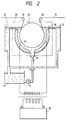
- Fig. 2 shows an electrolytic treatment apparatus for electrolytically treating a subject material, such as an aluminum web 11.
- the aluminum web 11 is conveyed via a first guide roller 13 along a supporting dram 12 to a second guide roller 13.
- the supporting dram 12 maintains a predetermined clearance between the web 11 and electrodes 16.
- a electrolytic solution 14 which includes primarily a nitric acid or a hydrochloric acid.
- the electrolytic solution is contained in an electrolyte treating tank 20 having a stock tank 19 for storing the electrolytic solution, and a pump 17 for feeding the solution through a supplying inlet 21.
- the solution is returned through overflow outlets 15.
- the tank also includes main electrodes 16 formed of a graphite.
- an assistant opposite electrode (not shown) is used to prevent deterioration of the main electrodes 16.
- the opposite electrode is connected to the output terminal of the power source circuit in parallel with the main electrodes 16.
- the assistant opposite electrode is made of platinum, lead, or similar material, but preferably, ferrite.
- the electrolytic treating tank 20 may also include devices to measure and/or control physical characteristics of the apparatus and electrolytic solution, such as a temperature controller and filters for removing unexpected particles.
- the power source circuit of Fig. 1 is coupled to the electrodes 16 and applies an alternating current thereto.
- the power source circuit 18 includes a rectifying coil 7 having an inductance larger than an inductance of the load 3 (i.e., main opposite electrodes 16 of the electrolytic treating tank 20 and bus line) and a current inverting control circuit to apply the alternating current from the AC side.
- the preferred frequency of the alternating current for roughening an aluminum support of the printing plate is larger than 15 Hz, although the frequency can be adjusted to suit the required quality.
- An electrolytic solution according to the present invention is a solution including primarily nitric acid or hydrochloric acid.
- a preferable concentration of the nitric acid is in the range of 5 - 50 g/l and a preferable concentration of aluminum ion in the electrolytic solution is in the range of 2 - 20 g/l.
- a preferable concentration of the hydrochloric acid is in the range of 5 - 100 g/l and a suitable concentration of aluminum ion is in the range of 2 - 30 g/l.
- the electrolytic current have a density in the range of 10 - 80 A/dm2 and the temperature of the electrolytic solution be above 30°C.
- an aluminum support is etched by an alkaline.
- a preferable alkaline agent includes caustic soda, caustic potash, metasilicate soda, sodium carbonate, aluminate soda, gluconate soda or the like, with the concentration of the alkaline agent in the range of 0.001 to 20%.
- the temperature of the etching liquid be in the range of 20 to 90°C
- the etching period be in the range of 5 sec. to 5 min
- the etching amount be between 0.01 to 5 g/m2.
- a preferable amount of etching is in the range of 0.01 - 1 g/m2. Additionally, since foreign insoluble particles remain on the surface of the aluminum plate, a treatment may be necessary to remove such particles.
- the aluminum plate is electrochemically roughened in an electrolytic solution by using the alternating current produced by the power source circuit 18.
- An electrolytic solution used in accordance with the present invention may be composed of a solution primarily containing nitric acid with a concentration in the range of 3 - 150 g/l, and preferably 5 - 50 g/l, and a concentration of aluminum ion not larger than 50 g/l, and preferably, in the range of 2 - 20 g/l.
- the electrolytic solution may be composed of a solution primarily containing a concentration of hydrochloric acid in the range of 2 - 250 g/l, more preferably, 5 - 100 g/l, and a concentration of aluminum ion not larger than 50 g/l, and more preferably, in the range of 2 - 30 g/l.
- an additive such as ammonium ion, however, in this case, it may be difficult to control the concentration of the solution for mass-production.
- the electric current is also preferable to supply the electric current at a current density in the range of 5 - 100 A/dm2, and preferably in the range of 10 - 80 A/dm2.
- a power source circuit 18 of Fig. 1 having an inductance of L1 equal to 10 mH was used in an electrolytic treatment.
- the value of the inductance in the electrolytic treating tank was 10 ⁇ H, and a turn ratio (N) of the transformer winding was 5:1. Therefore, the value of the inductance L2 of the load at the primary winding of the transformer was equal to 10 ⁇ H x (5)2 or 0.25 mH.
- the ratio of L1 to L2 equals 40 (i.e., 10/0.25).
- An electrolytic solution was prepared having a density of nitric acid of 10 g/l, a density of aluminum ion in the electrolytic solution of 7 g/l, and a temperature of 55°C.
- the electrolytic roughening treatment was performed with a voltage of 20 V applied to the capacitor 1 in the power source circuit 18 while supplying electric current to the electrolytic treating tank 20. Further, during the treatment, an electric quantity at the positive electrode was determined to be 300 coulomb, and the frequency of the alternating current was 40 Hz. When observing the current waveform just before the electrolytic treating tank by an oscilloscope, a top portion of the waveform was leveled and had a trapezoidal form as shown in Fig. 3. After roughening, an electron microscope was used to observe the surface where uniform pits had been formed in the plate.
- Example 1 The same electrolytic treating tank and electrolytic solution as used in Example 1 was used in this Comparative Example 1.
- the electrolytic roughening treatment was performed with the inductance L1 equaled 1 mH of the rectifying coil 7 in the power source circuit 18. All other conditions of the Comparative Example 1 were the same as Example 1.
- the ratio of the inductance L1/L2 equaled 4 (i.e., 1/0.25)
- the top flat portion of the current waveform is leveled, and the electrolytic roughening treatment is performed on an optimum condition of the pit and on a preferable condition of power supply cost to suffer a requirement of mass-production.
Landscapes
- Chemical & Material Sciences (AREA)
- Chemical Kinetics & Catalysis (AREA)
- Electrochemistry (AREA)
- Engineering & Computer Science (AREA)
- Materials Engineering (AREA)
- Metallurgy (AREA)
- Organic Chemistry (AREA)
- Automation & Control Theory (AREA)
- Printing Plates And Materials Therefor (AREA)
Abstract
Description
- The present invention relates to an apparatus and method for controlling an electrolytic roughening treatment of a material, such as a metal plate, and more particularly it relates to an apparatus and method of controlling the electrolytic reaction during an electrolytic roughening treatment a metal plate.
- It is known to use an aluminum plate (including an aluminum alloy) as a support for a printing plate such as a support for an offset printing plate. In such cases, a suitable adhesion and a suitable amount of water between the surface of the aluminum plate and a photosensitive layer is necessary. To achieve this, the surface of the aluminum plate must be uniform and finely roughened. If the aluminum plate is not finely roughened, both the printing performance and durability of the printing plate will be highly affected. Accordingly, it is important to achieve a satisfactory roughening of the plate during the manufacture thereof.
- In general, the roughening of an aluminum support of a printing plate involves the use of an alternating electrolytic etching method which, in turn, involves the use of an alternating current (e.g., a sine waveform, a square waveform, a special alternating waveform, etc.). The roughening treatment of the aluminum plate is performed by using a graphite electrode or the like disposed adjacent to the aluminum plate for applying the alternating current. The plate is usually only roughened once. As a result, the depth of pits formed by the roughening process in the plate is small over the whole surface thereof and the durability of the roughened printing plate for printing applications will deteriorate. Therefore, in order to obtain a uniformly and closely roughened aluminum plate having deep pits as compared with their diameters, a variety of methods are proposed. A first method is disclosed by Japanese Patent Laid-Open No. Sho. 53-67507, wherein a roughening method uses a current of particular waveform for an electrolytic source. Japanese Patent Laid-Open No. Sho. 54-65607 discloses another method which controls the ratio between an electrical quantity during a positive period and during a negative period at the time of alternating electrolytic roughening. Still another method is to control the waveform supplied from the electrolytic source (Japanese Patent Laid-Open No. Sho 55-25381). Finally, another method is directed to controlling the combination of current density (Japanese Patent Laid-Open No. Sho 56-29699).
- Japanese Patent Examined Publication No. Sho 61-60797, discloses a uniform roughened surface as a result of supplying an alternating current to the aluminum plate, in which at least one of the positive periods and negative periods includes a rest period of 0 Volt, so that the electricity quantity of the positive period may be larger than that of the negative period.
- However, when the aluminum plate is composed of an alloy, containing many ingredients (such as JIS3003 material), having an irregular yield of a small amount ingredients among the aluminum lots, it is likely to transform the roughened form and to change the printing performance.
- As a method to eliminate the above and other problems, particularly when using an alternating waveform, the inventor of the present invention provides a method (assuming that tf is the positive period and tr is the negative period), of applying an alternating current between an aluminum support and an electrode. The alternating current includes periods, in which the current reaches peak levels in both the positive and negative periods tf and tr, respectively, adjusted in the range of 0.1 - 20% of either period, thereby shortening the period it takes to reach the peak levels. This method then enables mass production and obtains a uniform roughening treatment, when using a power circuit including an inductive component larger than an inductive component of a load and a circuit to generate an alternating current by a current inverting control circuit. (Japanese Patent Laid-Open No. Hei. 3-82799).
- However, in a waveform controlled by the method of Japanese Patent Laid-Open No. Hei. 3-82799, when the current direction in the load changes, large electric power is required, in which a top line having a trapezoidal form of the output waveform develops a tendency to incline upward and rightward. As a result, pits are formed in the period develop some distributing ranges.
- Although the method disclosed in the publication satisfies the requirements of uniform pits, more satisfactory printing performance and more uniform pits are recently required and can be achieved using the invention as described below.
- Accordingly, it is an object of this invention is to provide a method of electrolytic treatment for roughening a metal plate, in which a metal plate is more uniformly roughened wherein the method does not consume large amounts of electric power.
- The above and other objects of the present invention are accomplished by providing an apparatus for subjecting a material to an electrolytic roughening treatment, including a tank for storing an electrolytic solution, a load comprising a transformer whose primary winding has a first inductance (L2), and first and second electrodes disposed in the tank, the first and second electrodes each have at least a surface in contact with the electrolytic solution, means for conveying the material through the electrolytic solution and adjacent to the first and second electrodes, a power source circuit, having first and second output terminals respectively coupled to the first and second electrodes. The power source circuit includes means for generating an alternating current, means for supplying the alternating current to the first and second output terminals, and a rectifying coil with an inductance (L1) that is at least ten times greater than the first inductance (L2).
-
- Fig. 1 illustrates a power source circuit according to the present invention;
- Fig. 2 illustrates an electrolytic treating tank including the power source circuit of Fig. 1 for performing an example of the method of the present invention; and
- Fig. 3 and 4 illustrate electric current waveforms in the respective electrolytic roughening treatments.
- The present invention will now be described in detail with reference to the accompanying drawings.
- Referring to Fig. 1, there is shown a power source circuit including a
DC power source 22. A first tap of theDC power source 22 is coupled to an end of a rectifyingcoil 7 having a predetermined inductance (L1). The other end of the rectifyingcoil 7 is coupled to a pair of invertingelements elements elements elements - With further reference to Fig. 1, the inverting elements are positioned so as to construct a bridge circuit wherein a first pair of the inverting
elements elements diodes capacitor 10 for supplying an electric charge in series. The capacitor 1 is also coupled to afeedback circuit 5 which is coupled to a waveform detecting circuit 6 of a load 3. - The output terminals A and B are also connected to the load 3, which includes a transformer wherein a primary winding of the transformer has an inductance of L₂. The inductance L₂ is converted from an inductance L₂, of the load 3 through the transformer 9, thereby reducing the period of reaching to peak current value at a positive electrode and a negative electrode. The inductance L₁ of the rectifying
coil 7 is at least 10 times the values of the inductance of the load L₂. - In operation, an alternating current is generated at the output terminals A and B of the bridge circuit by turning on and off the pair of inverting elements through the gate signal, which is generated by the
diodes 4a - 4d. - Fig. 2 shows an electrolytic treatment apparatus for electrolytically treating a subject material, such as an
aluminum web 11. Thealuminum web 11 is conveyed via afirst guide roller 13 along a supportingdram 12 to asecond guide roller 13. The supportingdram 12 maintains a predetermined clearance between theweb 11 andelectrodes 16. As the web is conveyed around the supportingdram 12, it is immersed in aelectrolytic solution 14 which includes primarily a nitric acid or a hydrochloric acid. - The electrolytic solution is contained in an electrolyte treating tank 20 having a
stock tank 19 for storing the electrolytic solution, and apump 17 for feeding the solution through a supplyinginlet 21. The solution is returned throughoverflow outlets 15. The tank also includesmain electrodes 16 formed of a graphite. Further, an assistant opposite electrode (not shown) is used to prevent deterioration of themain electrodes 16. The opposite electrode is connected to the output terminal of the power source circuit in parallel with themain electrodes 16. The assistant opposite electrode is made of platinum, lead, or similar material, but preferably, ferrite. - The electrolytic treating tank 20 may also include devices to measure and/or control physical characteristics of the apparatus and electrolytic solution, such as a temperature controller and filters for removing unexpected particles.
- The power source circuit of Fig. 1, is coupled to the
electrodes 16 and applies an alternating current thereto. As described above, thepower source circuit 18 includes a rectifyingcoil 7 having an inductance larger than an inductance of the load 3 (i.e., mainopposite electrodes 16 of the electrolytic treating tank 20 and bus line) and a current inverting control circuit to apply the alternating current from the AC side. The preferred frequency of the alternating current for roughening an aluminum support of the printing plate is larger than 15 Hz, although the frequency can be adjusted to suit the required quality. - An electrolytic solution according to the present invention is a solution including primarily nitric acid or hydrochloric acid. A preferable concentration of the nitric acid is in the range of 5 - 50 g/ℓ and a preferable concentration of aluminum ion in the electrolytic solution is in the range of 2 - 20 g/ℓ. On the other hand, a preferable concentration of the hydrochloric acid is in the range of 5 - 100 g/ℓ and a suitable concentration of aluminum ion is in the range of 2 - 30 g/ℓ. In addition, to achieve a uniform roughness, it is preferable that the electrolytic current have a density in the range of 10 - 80 A/dm² and the temperature of the electrolytic solution be above 30°C.
- An electrolytic treating process according to the present invention will now be described. Initially, a pre-treatment is performed as follows.
- First, an aluminum support is etched by an alkaline. A preferable alkaline agent includes caustic soda, caustic potash, metasilicate soda, sodium carbonate, aluminate soda, gluconate soda or the like, with the concentration of the alkaline agent in the range of 0.001 to 20%.
- Second, other preferred conditions require that the temperature of the etching liquid be in the range of 20 to 90°C, the etching period be in the range of 5 sec. to 5 min, and the etching amount be between 0.01 to 5 g/m².
- Third, for an aluminum support containing a relatively large amount of impurities of manganese or the like, a preferable amount of etching is in the range of 0.01 - 1 g/m². Additionally, since foreign insoluble particles remain on the surface of the aluminum plate, a treatment may be necessary to remove such particles.
- After performing a pre-treatment as described above, the aluminum plate is electrochemically roughened in an electrolytic solution by using the alternating current produced by the
power source circuit 18. - An electrolytic solution used in accordance with the present invention may be composed of a solution primarily containing nitric acid with a concentration in the range of 3 - 150 g/ℓ, and preferably 5 - 50 g/ℓ, and a concentration of aluminum ion not larger than 50 g/ℓ, and preferably, in the range of 2 - 20 g/ℓ. Alternatively, the electrolytic solution may be composed of a solution primarily containing a concentration of hydrochloric acid in the range of 2 - 250 g/ℓ, more preferably, 5 - 100 g/ℓ, and a concentration of aluminum ion not larger than 50 g/ℓ, and more preferably, in the range of 2 - 30 g/ℓ. In some instances, it is possible to add an additive such as ammonium ion, however, in this case, it may be difficult to control the concentration of the solution for mass-production.
- It is also preferable to supply the electric current at a current density in the range of 5 - 100 A/dm², and preferably in the range of 10 - 80 A/dm².
- The above ranges are provided as an example and are not meant to limit the present invention in any manner as it is often necessary to select many various conditions in view of the desired quality, composition of the aluminum support, and the like.
- A
power source circuit 18 of Fig. 1 having an inductance of L₁ equal to 10 mH was used in an electrolytic treatment. The value of the inductance in the electrolytic treating tank was 10 µH, and a turn ratio (N) of the transformer winding was 5:1. Therefore, the value of the inductance L₂ of the load at the primary winding of the transformer was equal to 10 µH x (5)² or 0.25 mH. Thus, the ratio of L₁ to L₂ equals 40 (i.e., 10/0.25). - An electrolytic solution was prepared having a density of nitric acid of 10 g/ℓ, a density of aluminum ion in the electrolytic solution of 7 g/ℓ, and a temperature of 55°C.
- The electrolytic roughening treatment was performed with a voltage of 20 V applied to the capacitor 1 in the
power source circuit 18 while supplying electric current to the electrolytic treating tank 20. Further, during the treatment, an electric quantity at the positive electrode was determined to be 300 coulomb, and the frequency of the alternating current was 40 Hz. When observing the current waveform just before the electrolytic treating tank by an oscilloscope, a top portion of the waveform was leveled and had a trapezoidal form as shown in Fig. 3. After roughening, an electron microscope was used to observe the surface where uniform pits had been formed in the plate. - The same electrolytic treating tank and electrolytic solution as used in Example 1 was used in this Comparative Example 1. The electrolytic roughening treatment was performed with the inductance L₁ equaled 1 mH of the rectifying
coil 7 in thepower source circuit 18. All other conditions of the Comparative Example 1 were the same as Example 1. - Accordingly, the ratio of the inductance L₁/L₂ equaled 4 (i.e., 1/0.25)
- When observing the current waveform by an oscilloscope, a top portion of the waveform had been inclined and had ripples as shown in Fig. 4. After the roughening, the surface of the roughened plate was again observed and pits formed in the plate were found to be non-uniform and having depths between 10 to 20 µm.
- According to the electrolytic treating method of the present invention, the top flat portion of the current waveform is leveled, and the electrolytic roughening treatment is performed on an optimum condition of the pit and on a preferable condition of power supply cost to suffer a requirement of mass-production.
- There has thus been shown and described a novel apparatus and method for controlling an electrolytic treatment of a subject material which fulfills all the objects and advantages sought therefor. Many changes, modifications, variations, and other uses and applications of the subject invention will, however, become apparent to those skilled in the art after considering the specification and the accompanying drawings which disclose preferred embodiments thereof. All such changes, modifications, variations, and other uses and applications which do not depart from the spirit and scope of the invention are deemed to be covered by the invention which is limited only by the claims which follow.
Claims (9)
- An apparatus for subjecting a material to an electrolytic roughening treatment, comprising:
a tank for storing an electrolytic solution;
a load comprising a transformer whose primary winding has a first inductance (L2), and first and second electrodes disposed in said tank, said first and second electrodes each having at least a surface in contact with said electrolytic solution;
means for conveying the material through the electrolytic solution and adjacent to said first and second electrodes;
a power source circuit, having first and second output terminals respectively coupled to said first and second electrodes, said power source circuit comprising means for generating an alternating current, means for supplying said alternating current to said first and second output terminals; and
a rectifying coil having an inductance (L1), being at least ten times greater than the first inductance (L2). - An apparatus as defined by Claim 1, wherein said power source circuit further comprising a first pair of inverting elements coupled to said first output terminal; a second pair of inverting elements coupled to said second output terminal; and means for turning on and off said first and second pairs of inverting elements in an alternating fashion so as to output an alternating current.
- An apparatus as defined by Claim 1, wherein the material is one of an aluminum web and an aluminum alloy web.
- An apparatus as defined by Claim 2, wherein said inverting elements are gate-turn-off thyristers.
- A method for electrochemically roughening a surface of metal plate comprising the steps of:
providing the metal plate;
contacting said plate with an electrolytic solution;
applying to said plate through adjacent electrodes and said solution an alternating current generated by a power source circuit containing a rectifying coil having an inductance at least ten times greater than an inductance of a load. - A method as defined by Claim 5, wherein said electrolytic solution comprises nitric acid with a concentration in the range of 3 - 150 g/ℓ; and a concentration of aluminum ion not larger than 50 g/ℓ.
- A method as defined by Claim 6, wherein said electrolytic solution comprises nitric acid with a concentration in the range of 5 - 50 g/ℓ, and a concentration of aluminum ion in the range of 2 - 20 g/ℓ.
- A method as defined by Claim 5, wherein said electrolytic solution comprises hydrochloric acid in the range of 2 - 250 g/ℓ; and a concentration of aluminum ion not larger than 50 g/ℓ.
- A method as defined by Claim 8, wherein said electrolytic solution comprises hydrochloric acid in the range of 5 - 100 g/ℓ; and a concentration of aluminum ion in the range of 2 - 30 g/ℓ.
Applications Claiming Priority (2)
| Application Number | Priority Date | Filing Date | Title |
|---|---|---|---|
| JP3315246A JP2707381B2 (en) | 1991-11-05 | 1991-11-05 | Electrolytic treatment of aluminum support for printing plate |
| JP315246/91 | 1991-11-05 |
Publications (3)
| Publication Number | Publication Date |
|---|---|
| EP0545092A2 true EP0545092A2 (en) | 1993-06-09 |
| EP0545092A3 EP0545092A3 (en) | 1994-03-16 |
| EP0545092B1 EP0545092B1 (en) | 1996-04-24 |
Family
ID=18063131
Family Applications (1)
| Application Number | Title | Priority Date | Filing Date |
|---|---|---|---|
| EP92118900A Expired - Lifetime EP0545092B1 (en) | 1991-11-05 | 1992-11-04 | An apparatus and method for controlling an electrolytic treatment of a subject material |
Country Status (4)
| Country | Link |
|---|---|
| US (1) | US5328573A (en) |
| EP (1) | EP0545092B1 (en) |
| JP (1) | JP2707381B2 (en) |
| DE (1) | DE69210184T2 (en) |
Cited By (1)
| Publication number | Priority date | Publication date | Assignee | Title |
|---|---|---|---|---|
| EP0887203A1 (en) * | 1997-06-23 | 1998-12-30 | Konica Corporation | Manufacturing method of planographic printing plate support and presensitized planographic printing plate |
Families Citing this family (4)
| Publication number | Priority date | Publication date | Assignee | Title |
|---|---|---|---|---|
| DE69610002T2 (en) * | 1995-03-06 | 2001-01-11 | Fuji Photo Film Co., Ltd. | Support for lithographic printing plates, production process therefor and device for electrochemical roughening |
| US6620306B2 (en) * | 2000-11-29 | 2003-09-16 | Matsushita Electric Industrial Co., Ltd. | Method of manufacturing electrode foil for aluminum electrolytic capacitor and AC power supply unit |
| US20080253922A1 (en) * | 2007-04-13 | 2008-10-16 | General Electric Company | Method for roughening metal surfaces and article manufactured thereby |
| US8974656B2 (en) * | 2007-04-13 | 2015-03-10 | General Electric Company | Method for roughening metal surfaces and article manufactured thereby |
Citations (1)
| Publication number | Priority date | Publication date | Assignee | Title |
|---|---|---|---|---|
| JPH0382799A (en) * | 1989-08-24 | 1991-04-08 | Fuji Photo Film Co Ltd | Electrolytic treatment |
Family Cites Families (4)
| Publication number | Priority date | Publication date | Assignee | Title |
|---|---|---|---|---|
| DE3503927A1 (en) * | 1985-02-06 | 1986-08-07 | Hoechst Ag, 6230 Frankfurt | METHOD FOR ELECTROCHEMICALLY Roughening ALUMINUM FOR PRINTING PLATE CARRIERS |
| DE3503926A1 (en) * | 1985-02-06 | 1986-08-07 | Hoechst Ag, 6230 Frankfurt | METHOD FOR ELECTROCHEMICALLY Roughening ALUMINUM FOR PRINTING PLATE CARRIERS |
| DE3910213A1 (en) * | 1989-03-30 | 1990-10-11 | Hoechst Ag | METHOD AND DEVICE FOR Roughening A SUPPORT FOR LIGHT-SENSITIVE LAYERS |
| US5221442A (en) * | 1991-03-07 | 1993-06-22 | Fuji Photo Film Co., Ltd. | Method and apparatus for electrolytic treatment |
-
1991
- 1991-11-05 JP JP3315246A patent/JP2707381B2/en not_active Expired - Fee Related
-
1992
- 1992-11-04 EP EP92118900A patent/EP0545092B1/en not_active Expired - Lifetime
- 1992-11-04 DE DE69210184T patent/DE69210184T2/en not_active Expired - Fee Related
- 1992-11-05 US US07/971,575 patent/US5328573A/en not_active Expired - Lifetime
Patent Citations (1)
| Publication number | Priority date | Publication date | Assignee | Title |
|---|---|---|---|---|
| JPH0382799A (en) * | 1989-08-24 | 1991-04-08 | Fuji Photo Film Co Ltd | Electrolytic treatment |
Non-Patent Citations (1)
| Title |
|---|
| DATABASE WPI Section Ch, Week 9120, Derwent Publications Ltd., London, GB; Class G05, AN 91-145605 & JP-A-3 082 799 (FUJI PHOTO FILM) 8 April 1991 * |
Cited By (2)
| Publication number | Priority date | Publication date | Assignee | Title |
|---|---|---|---|---|
| EP0887203A1 (en) * | 1997-06-23 | 1998-12-30 | Konica Corporation | Manufacturing method of planographic printing plate support and presensitized planographic printing plate |
| US6045681A (en) * | 1997-06-23 | 2000-04-04 | Konica Corporation | Manufacturing method of planographic printing plate support and presensitized planographic printing plate |
Also Published As
| Publication number | Publication date |
|---|---|
| DE69210184D1 (en) | 1996-05-30 |
| DE69210184T2 (en) | 1996-09-05 |
| JPH05125599A (en) | 1993-05-21 |
| EP0545092B1 (en) | 1996-04-24 |
| JP2707381B2 (en) | 1998-01-28 |
| EP0545092A3 (en) | 1994-03-16 |
| US5328573A (en) | 1994-07-12 |
Similar Documents
| Publication | Publication Date | Title |
|---|---|---|
| EP0659909B1 (en) | Electrochemical graining method | |
| US6024858A (en) | Method of producing an aluminum support for a planographic plate | |
| EP0422682B1 (en) | Method for producing support for printing plate | |
| US5141605A (en) | Process for producing aluminum support of a printing plate | |
| EP0545092B1 (en) | An apparatus and method for controlling an electrolytic treatment of a subject material | |
| US5082537A (en) | Process and apparatus for roughening a substrate for photosensitive layers | |
| EP0414189B1 (en) | Method of producing aluminum support for printing plate | |
| NL8303736A (en) | METHOD FOR REMOVING GALVANIC-deposited NICKEL, CHROME OR GOLD LAYERS FROM COPPER OR COPPER ALLOY SURFACES, AND APPARATUS FOR CARRYING OUT THIS PROCESS | |
| US4872946A (en) | Method of manufacturing supports for lithographic printing plate | |
| EP0134580B1 (en) | Method and apparatus for electrolytic treatment | |
| EP0194317B1 (en) | Method of producing electrolytic capacitors. | |
| EP0189595B2 (en) | Method for etching electrode foils for an aluminium electrolytic capacitor | |
| EP0554899A1 (en) | Electrical discharge machine with secondary electrode for corrosion prevention | |
| EP0502507B1 (en) | Method and apparatus for electrolytic treatment | |
| US5271818A (en) | Apparatus for roughening a substrate for photosensitive layers | |
| JP2003171800A (en) | Electrolyzer | |
| EP0349983A2 (en) | Electrolytic treatment apparatus | |
| JP2715346B2 (en) | Electrolytic treatment of aluminum support for printing plate | |
| US6344131B1 (en) | Method of producing aluminum support for planographic printing plate | |
| WO1995018250A1 (en) | Method of producing a coating on metals with unipolar conductivity | |
| US5213666A (en) | Method of preparing support for printing plate | |
| JP2715344B2 (en) | Electrolytic treatment of aluminum support for printing plate | |
| US6261438B1 (en) | Method and apparatus for roughening a support for radiation-sensitive coatings | |
| JPH0762599A (en) | Electrolytic device of conductive plate material | |
| JP2614112B2 (en) | Electrolytic treatment of aluminum support for printing plate |
Legal Events
| Date | Code | Title | Description |
|---|---|---|---|
| PUAI | Public reference made under article 153(3) epc to a published international application that has entered the european phase |
Free format text: ORIGINAL CODE: 0009012 |
|
| AK | Designated contracting states |
Kind code of ref document: A2 Designated state(s): DE GB NL |
|
| PUAL | Search report despatched |
Free format text: ORIGINAL CODE: 0009013 |
|
| AK | Designated contracting states |
Kind code of ref document: A3 Designated state(s): DE GB NL |
|
| 17P | Request for examination filed |
Effective date: 19940628 |
|
| 17Q | First examination report despatched |
Effective date: 19941110 |
|
| RBV | Designated contracting states (corrected) |
Designated state(s): DE |
|
| GRAH | Despatch of communication of intention to grant a patent |
Free format text: ORIGINAL CODE: EPIDOS IGRA |
|
| GRAA | (expected) grant |
Free format text: ORIGINAL CODE: 0009210 |
|
| AK | Designated contracting states |
Kind code of ref document: B1 Designated state(s): DE |
|
| REF | Corresponds to: |
Ref document number: 69210184 Country of ref document: DE Date of ref document: 19960530 |
|
| PLBE | No opposition filed within time limit |
Free format text: ORIGINAL CODE: 0009261 |
|
| STAA | Information on the status of an ep patent application or granted ep patent |
Free format text: STATUS: NO OPPOSITION FILED WITHIN TIME LIMIT |
|
| 26N | No opposition filed | ||
| PGFP | Annual fee paid to national office [announced via postgrant information from national office to epo] |
Ref country code: DE Payment date: 20041028 Year of fee payment: 13 |
|
| PG25 | Lapsed in a contracting state [announced via postgrant information from national office to epo] |
Ref country code: DE Free format text: LAPSE BECAUSE OF NON-PAYMENT OF DUE FEES Effective date: 20060601 |