EP0542792B1 - Process for the in-line hydrolysis of urea - Google Patents
Process for the in-line hydrolysis of urea Download PDFInfo
- Publication number
- EP0542792B1 EP0542792B1 EP91913756A EP91913756A EP0542792B1 EP 0542792 B1 EP0542792 B1 EP 0542792B1 EP 91913756 A EP91913756 A EP 91913756A EP 91913756 A EP91913756 A EP 91913756A EP 0542792 B1 EP0542792 B1 EP 0542792B1
- Authority
- EP
- European Patent Office
- Prior art keywords
- urea
- urea solution
- hydrolysis
- effluent
- solution
- Prior art date
- Legal status (The legal status is an assumption and is not a legal conclusion. Google has not performed a legal analysis and makes no representation as to the accuracy of the status listed.)
- Expired - Lifetime
Links
Images

Classifications
-
- B—PERFORMING OPERATIONS; TRANSPORTING
- B01—PHYSICAL OR CHEMICAL PROCESSES OR APPARATUS IN GENERAL
- B01D—SEPARATION
- B01D53/00—Separation of gases or vapours; Recovering vapours of volatile solvents from gases; Chemical or biological purification of waste gases, e.g. engine exhaust gases, smoke, fumes, flue gases, aerosols
- B01D53/34—Chemical or biological purification of waste gases
- B01D53/46—Removing components of defined structure
- B01D53/54—Nitrogen compounds
- B01D53/56—Nitrogen oxides
-
- C—CHEMISTRY; METALLURGY
- C01—INORGANIC CHEMISTRY
- C01C—AMMONIA; CYANOGEN; COMPOUNDS THEREOF
- C01C1/00—Ammonia; Compounds thereof
- C01C1/02—Preparation, purification or separation of ammonia
- C01C1/08—Preparation of ammonia from nitrogenous organic substances
- C01C1/086—Preparation of ammonia from nitrogenous organic substances from urea
-
- F—MECHANICAL ENGINEERING; LIGHTING; HEATING; WEAPONS; BLASTING
- F01—MACHINES OR ENGINES IN GENERAL; ENGINE PLANTS IN GENERAL; STEAM ENGINES
- F01N—GAS-FLOW SILENCERS OR EXHAUST APPARATUS FOR MACHINES OR ENGINES IN GENERAL; GAS-FLOW SILENCERS OR EXHAUST APPARATUS FOR INTERNAL-COMBUSTION ENGINES
- F01N2240/00—Combination or association of two or more different exhaust treating devices, or of at least one such device with an auxiliary device, not covered by indexing codes F01N2230/00 or F01N2250/00, one of the devices being
- F01N2240/40—Combination or association of two or more different exhaust treating devices, or of at least one such device with an auxiliary device, not covered by indexing codes F01N2230/00 or F01N2250/00, one of the devices being a hydrolysis catalyst
-
- Y—GENERAL TAGGING OF NEW TECHNOLOGICAL DEVELOPMENTS; GENERAL TAGGING OF CROSS-SECTIONAL TECHNOLOGIES SPANNING OVER SEVERAL SECTIONS OF THE IPC; TECHNICAL SUBJECTS COVERED BY FORMER USPC CROSS-REFERENCE ART COLLECTIONS [XRACs] AND DIGESTS
- Y02—TECHNOLOGIES OR APPLICATIONS FOR MITIGATION OR ADAPTATION AGAINST CLIMATE CHANGE
- Y02C—CAPTURE, STORAGE, SEQUESTRATION OR DISPOSAL OF GREENHOUSE GASES [GHG]
- Y02C20/00—Capture or disposal of greenhouse gases
- Y02C20/10—Capture or disposal of greenhouse gases of nitrous oxide (N2O)
Definitions
- the present invention relates to a process for the in-line hydrolysis of urea in order to facilitate the reduction of nitrogen oxides (NO x ) in a combustion effluent.
- the reduction of nitrogen oxides is accomplished by utilizing the hydrolysis products of urea to minimize the generation of nitrous oxide (N2O).
- Carbonaceous fuels can be made to burn more completely and with reduced emissions of carbon monoxide and unburned hydrocarbons when the oxygen concentrations and air/fuel ratios employed are those which permit high-flame temperatures.
- temperatures above about 1093°C (2000°F) and typically about 1204°C (2200°F) to about 1649°C (3000°F) are generated.
- thermal NO x the temperatures being so high that free radicals of oxygen and nitrogen are formed and chemically combine as nitrogen oxides.
- Nitrogen oxides can form even in circulating fluidized bed boilers which operate at temperatures which typically range from 704°C (1300°F) to 927°C (1700°F), as well as gas turbines and diesel engines.
- Nitrogen oxides are troublesome pollutants which are found in the combustion streams of boilers when fired as described above, and comprise a major irritant in smog. It is further believed that nitrogen oxides can undergo a process known as photochemical smog formation, through a series of reactions in the presence of some hydrocarbons. Moreover, nitrogen oxides comprise a significant contributor to acid rain and have been implicated as contributing to the undesirable depletion of the ozone layer. They may also impact on the warming of the atmosphere commonly referred to as "the greenhouse effect”. Some or all of these effects are also believed to be attributable to nitrous oxide.
- SNCR processes which are temperature dependent, generally utilize a nitrogenous substance such as urea or ammonia, as well as non-nitrogenous substances, and proceed in the gas phase by a complex series of free radical-mediated chemical reactions and involve various nitrogen, hydrogen, oxygen, and carbon-containing species and radicals.
- a nitrogenous substance such as urea or ammonia
- non-nitrogenous substances and proceed in the gas phase by a complex series of free radical-mediated chemical reactions and involve various nitrogen, hydrogen, oxygen, and carbon-containing species and radicals.
- Urea is generally considered the most desirable NO x reducing species because of its effectiveness and relatively broad temperature window, as well as its relatively non-toxic and environmentally benign nature.
- Urea breaks down into the amino radical (NH2 ⁇ ), which is believed to be the moiety responsible for the reduction of NO x , but can also, under certain conditions, break down into cyanic or isocyanic acid according to the following reaction formula 2NH2CONH2 + OH ⁇ ⁇ 3NH2 ⁇ + HOCN (or HNCO) + H2O + CO
- the amido radical can then proceed to reduce NO x according to the following reaction pathway NH2 ⁇ + NO ⁇ N2 + H2O but the cyanic or isocyanic acid produced can then proceed further to form nitrous oxide and carbon monoxide or molecular nitrogen and carbon dioxide when combined with NO x according to the following set of reactions HOCN (or HNCO) + OH ⁇ ⁇ NCO ⁇ + H2O NCO ⁇ + NO ⁇ N2O + CO NCO ⁇ + NO ⁇ N2 + CO2
- N2O is formed, the effectiveness of urea is somewhat decreased, although NO x is being substantially reduced, because another pollutant species, N2O
- the present invention relates to a process for the reduction of nitrogen oxides in a combustion effluent, the process comprising an aqueous solution of urea, while flowing through a conduit of a nitrogen oxides reduction apparatus, being heated to a temperature and for a time effective to hydrolyze urea to produce hydrolysis products comprising ammonium carbamate, ammonium carbonate, ammonium bicarbonate, and ammonia, and introducing said hydrolysis products into the combustion effluent under conditions effective to reduce the nitrogen oxides concentration therein.
- the hydrolysis reaction can be improved by conducting it in an acidic or a basic environment or in the presence of certain catalysts or enzymes.
- the present invention further relates to an apparatus for treating a combustion effluent in accordance with the subject matter of claim 20.
- the present invention relates to the in-line hydrolysis of urea for the formation of hydrolysis products which can be introduced into a combustion effluent for the reduction of nitrogen oxides without the generation of nitrous oxide.
- the hydrolysis products produced include ammonium carbamate (NH2COONH4), ammonium carbonate ((NH4)2CO3) and a mixture of ammonia (NH3) and ammonium bicarbonate (NH4HCO3).
- NH2COONH4 ammonium carbamate
- (NH4)2CO3) ammonium carbonate
- NH3 ammonium bicarbonate
- each of these hydrolysis products is commercially available, it is more desirable to produce them by in-line hydrolysis because of the stability and relative safety of urea for transport and storage.
- ammonium carbonate and ammonium bicarbonate are substantially lower than that of urea, limiting their usefulness as a starting material.
- these hydrolysis products can break down to form amino radicals which combine with nitrogen oxides as noted above to reduce them to N2.
- Hydrolysis of urea can be performed in-line, for instance while the urea is being supplied to an injector or other introduction means to be introduced into a combustion effluent.
- This can be accomplished by passing an aqueous solution of urea, at a concentration of about 5% to about 45%, advantageously about 7% to about 15%, through a supply conduit (referred to as a reaction conduit or tube) and applying heat and pressure, maintaining the pressure above the partial pressure of the system NH4 ⁇ /NH3/CO2/H2O at the selected temperature.
- the conduit can be any of the conventional tubes or pipes currently used to supply urea solutions to a combustion effluent in a NO x reducing apparatus.
- the urea solution is raised to a temperature and for a time effective to hydrolyze the urea to ammonium carbamate, ammonium carbonate, ammonium bicarbonate, and ammonia.
- temperatures are no greater than about 260°C (500°F), and preferably range from about 149°C (300°F) to about 232°C (450°F), more preferably about 163°C (325°F) to about 191°C (375°F) for a period of time of at least about three minutes in order to achieve substantial hydrolysis of the urea.
- hydrolysis need only proceed for a maximum of about six minutes for substantial completion.
- This reaction can be increased by also maintaining the urea solution under pressure, preferably pressure in excess of about 84.37 kilograms per square centimeter (at) (1,200 pounds per square inch (psi)), more preferably pressures pounds per square inch (psi)), more preferably pressures in excess of about 105.5 at (1,500 psi).
- hydrolysis by the application of heat and pressure is effective for urea hydrolysis
- this hydrolysis reaction can be promoted (i.e., the efficiency increased) by the addition of a hydrolysis agent, such as one which functions by either raising or lowering the pH of the aqueous urea solution, together with or sequentially after application of heat (and pressure).
- a hydrolysis agent such as one which functions by either raising or lowering the pH of the aqueous urea solution, together with or sequentially after application of heat (and pressure).
- a pH neutral urea solution can be made more alkaline or more acidic to promote hydrolysis.
- the pH of the aqueous urea solution is raised by the addition of an alkaline agent such as potassium hydroxide, sodium hydroxide, calcium hydroxide, calcium ammonia and ammonium bicarbonate.
- an alkaline agent such as potassium hydroxide, sodium hydroxide, calcium hydroxide, calcium ammonia and ammonium bicarbonate.
- the temperature to which the urea solution is raised need not be as high as if heat were being utilized alone in order to achieve equivalent results.
- the temperature need only be raised to temperatures not exceeding about 204°C (400°F), especially about 138°C (280°F) to about 188°C (370°F) and preferably about 149°C (300°F) to about 177°C (350°F).
- the pressure of the solution need only be raised to about 31.6 at (450 psi) to about 42.2 at (600 psi), preferably about 35.1 at (500 psi) to 39.4 at (560 psi).
- the temperatures and pressures applied when heat is used alone for hydrolysis are used when basic hydrolysis is employed, in order to provide significant increases in the efficiency of the hydrolysis reaction.
- the pH of the aqueous urea solution is lowered, for instance by the addition of an acid or acid salt especially in solution, such as a buffered solution.
- acid or acid salts include sulfuric acid, hydrochloric acid, formic acid, acetic acid, citric acid, ammonium hydrogen sulfate, or mixtures thereof.
- formic acid and acetic acid are advantageous in this respect, because when combined with the hydrolysis product ammonia they can form the ammonium salts, ammonium acetate, and ammonium formate.
- These salts have been suggested as having a NO x reducing effect at temperatures below those of urea.
- the pH of the solution when acidic hydrolysis is employed is brought to a level below about pH 5, most preferably below about pH 3 in order to substantially promote the hydrolysis of urea, although this is not critical.
- the temperature need not be raised to those when heat is being used for hydrolysis alone.
- the temperature need only be raised to temperatures no greater than about 204°C (400°F), especially about 138°C (280°F) to about 189°C (370°F) and most preferably about 149°C (300°F) to about 177°C (350°F) in order to achieve results equivalents to those achieved with hydrolysis mediated by heat only.
- the pressure need only be raised to those used for basic hydrolysis. It is desired, though, that the application of heat and pressure be in the ranges discussed above for hydrolysis by heat alone in order to achieve increased hydrolysis efficiency.
- the acidic or basic agent being added is admixed with the aqueous urea solution immediately before or during the application of heat and pressure, or immediately thereafter.
- the admixed solution is maintained for a period of about three to six minutes prior to introduction into the effluent, although the upper time limit is not considered critical.
- urea hydrolysis can also be performed using, as the hydrolysis agent, suitable catalysts or enzymes, in either a heterogeneous or homogeneous system.
- the catalyst is present on a fixed bed, for instance as a coating on the inside of the conduit through which the urea solution is flowing or on installations in the path of the flow; or in the form of catalyst particles suspended in the urea solution.
- Both the fixed bed and suspended catalyst particles preferably contain metals, especially metal oxides, metal salts, or mixtures thereof as the active catalyst ingredient.
- suitable metals include copper, vanadium, iron, nickel, chromium, manganese, and their oxides and salts, especially their sulfate or chromate salts.
- a suspension of flue-ash or a suspension of oil black which can be found in vessels operated with heavy oil, can also be used as a heterogeneous catalyst.
- the aqueous urea solution can be admixed with catalyst in the form of water soluble metal salts, for instance, the sulfate or nitrate salts of metal such as copper and nickel.
- catalyst in the form of water soluble metal salts, for instance, the sulfate or nitrate salts of metal such as copper and nickel.
- filtrates of flue-ash suspension can also be utilized as catalyst.
- Urea hydrolysis can also be performed utilizing enzymes such as urease as a catalyst for the hydrolysis reaction.
- the enzyme can be added as it is or attached to an inert carrier particle in order to perform hydrolysis in the urea solution.
- the mixture of the enzyme with the aqueous urea solution is preferably circulated in a reactor with the hydrolysis products removed via a separation element. These hydrolysis products can then be introduced into the combustion effluent.
- Suitable separation elements include filter elements such as ultra filtration membranes.
- the enzyme can also be bound to in immobile phase which can be present in the reaction conduit, for instance, in the form of hollow fibers or other carrier particles.
- the hydrolysis products can be introduced into the effluent by suitable introduction means under conditions effective to reduce the effluent nitrogen oxides concentration in a selective, non-catalytic, gas-phase process.
- suitable introduction means include injectors, such as those disclosed by Burton in US-A-4,842,834, or DeVita in US-A-4,915,036.
- injectors such as those disclosed by Burton in US-A-4,842,834, or DeVita in US-A-4,915,036.
- One preferred type of injection means is an injection lance, especially a lance of the type disclosed by Peter-Hoblyn and Grimard in International Application PCT/EP89/00765, filed July 4, 1989, entitled "Lance-Type Injection Apparatus".
- the hydrolyzed urea solution of this invention is introduced into the effluent in an amount effective to elicit a reduction in the nitrogen oxides concentration in the effluent.
- the hydrolyzation products are introduced into the effluent in an amount sufficient to provide a molar ratio of the nitrogen contained in the solution to the baseline nitrogen oxides level (by which is meant the pretreatment level of NO x in the effluent) of about 1:5 to about 10:1.
- the hydrolyzed solution is introduced into the effluent to provide a molar ratio of solution nitrogen to baseline nitrogen oxides level of about 1:3 to about 5:1, most preferably about 1:2 to about 3:1.
- the hydrolyzed urea solution produced by the process of this invention is preferably injected into the effluent gas stream at a point where the effluent is at a temperature above about 704°C (1300°F), more preferably above about 760°C (1400°F).
- Large industrial and circulating fluidized bed boilers of the types employed for utility power plants and other large facilities will typically have access only at limited points. In the most typical situations, the boiler interior in the area above the flame operates at temperatures which at full load approach 1204°C (2200°F), even 1260°C (2300°F). After subsequent heat exchange, the temperature will be lower, usually in the range between about 704°C (1300°F) and 1149°C (2100°F). At these temperatures, the hydrolyzation products produced in accordance with this invention can be effectively introduced to accomplish substantial reduction of nitrogen oxides in the effluent without the generation of significant amounts of nitrous oxide.
- the hydrolyzation products can be enhanced by other compositions such as hexamethylenetetramine (HMTA), oxygenated hydrocarbons such as ethylene glycol, ammonium salts of organic acids such as ammonium acetate and ammonium benzoate, heterocyclic hydrocarbons having at least one cyclic oxygen such am furfural, molasses, sugar, 5- or 6-membered heterocyclic hydrocarbons having at least one cyclic nitrogen such as pyridine and pyrolidine, hydroxy amino hydrocarbons such as milk or skimmed milk, amino acids, proteins, and monoethanolamine and various other compounds which are disclosed as being effective at reducing nitrogen oxides in an effluent.
- HMTA hexamethylenetetramine
- oxygenated hydrocarbons such as ethylene glycol
- ammonium salts of organic acids such as ammonium acetate and ammonium benzoate
- heterocyclic hydrocarbons having at least one cyclic oxygen such am furfural, molasses, sugar
- Such enhancers as well as others which may be suitable are disclosed in, for instance, US-A-4,751,065; US-A-4,927,612; US-A-4,719,092; US-A-4,888,164; US-A-4,877,591; US-A-4,803,059; US-A-4,844,878; US-A-4,873,066; US-A-4,770,863; US-A-4,902,488; US-A-4,863,704; US-A-4,863,705; and International Patent Application entitled "Composition for Introduction into a High Temperature Environment", having Publication No. WO-A-8910182, filed in the names of Epperly, Sprague, and von Harpe on April 26, 1989.
- the solution When the solution is introduced without a non-nitrogenous hydrocarbon component, it is preferably introduced at an effluent temperature of about 871°C (1600°F) to about 1149°C (2100°F), more preferably about 927°C (1700°F) to about 1149°C (2100°F).
- the solution also comprises one of the enhancers discussed above, it is preferably introduced at an effluent temperature of about 704°C (1300°F) to about 954°C (1750°F), more preferably about 760°C (1400°F) to about 954°C (1750°F) or higher.
- These effluent temperatures at the point of introduction can be varied depending on the particular components of the treatment agent and other effluent conditions, such as the effluent oxygen level, as discussed in the referenced disclosures.
- the effluent into which the hydrolyzation products of this invention is injected is preferably oxygen-rich, meaning that there is an excess of oxygen in the effluent.
- the excess of oxygen is greater than about 1% by volume. Most preferably, the excess of oxygen is in the range of about 1% to about 12% or greater by volume.
- the in-line hydrolysis of urea is carried out by mixing an aqueous urea solution with the acid, base, or catalyst in a static mixer. This mixture is then heated, such as by passing through a heat exchanger or other suitable apparatus, and brought to the desired pressure and then passed to a decompression vessel in which the pressure is lowered, which causes the mixture to undergo separation into a liquid and gaseous phase.
- the liquid phase contains the liquid or liquid soluble hydrolysis products, ammonium carbamate, ammonium carbonate, and ammonium bicarbonate, which can then be introduced into the effluent, and the gaseous phase comprises the hydrolysis product ammonia, as well as carbon dioxide, which can also be introduced into the effluent.
- the gases ammonia and carbon dioxide remain dissolved in the aqueous solution. Under these conditions the decompression vessel is not needed and the mixture itself can be directly introduced into the effluent.
- the mixture of the aqueous urea solution with the acidic or basic agents or the catalyst is heated while passing through the conduits as described above to the injector with hydrolysis occurring in line and the hydrolyzed urea solution introduced directly into the effluent.
- the heat exchanger for heating the urea solution may be positioned in the effluent stream and as a result of this, the heat required for facilitating the urea hydrolysis reaction is withdrawn from the effluent to avoid the need for an independent heat source.
- Such heat exchanger preferably forms a unit together with the apparatus on which the injection means are arranged within the effluent stream.
- the heat exchanger at the same time cools the injector means, such as the injection lances, which is desirable at high combustion temperatures.
- the heat exchanger is preferably constructed in the form of a jacket around the injection lance.
- the heated and hydrolyzed urea solution is passed from the heat exchanger to a flash drum positioned outside the effluent, and the gaseous or liquid phase formed is separately supplied to the injectors of the injection lance, while pressurized air may optionally be added to the gaseous phase.
- the decompression vessel can be dispensed with and the hydrolyzed urea solution can be injected directly.
- the urea solution is recycled together with the enzyme to an intermediate stirring vessel or through a fixed bed of immobilized enzyme.
- the hydrolyzed products are then optionally withdrawn via a filter element and introduced into the effluent.
- FIG. 1 A typical apparatus for achieving acidic, basic, or catalytic hydrolysis with introduction of the hydrolysis products into the effluent is illustrated in Figure 1.
- the illustrated apparatus 10 comprises a urea storage tank 20, a hydrolyzing agent storage tank 30 (for the acid, base, or catalyst), a water supply line 11, a pressurized air supply line 12, a static mixer 40, a heat exchanger 50, a reaction conduit 60, a decompression vessel 70, an entrainment jet 13, and an injection means 80, which extends into the effluent 100.
- Urea solution is supplied from urea storage tank 20, hydrolyzation agent from storage tank 30, and dilution water are all supplied to static mixer 40, via pumps 14, 15, and 16.
- the resultant mixture is heated to the desired temperature in heat exchanger 50, passes through reaction conduit 60, and is supplied to the decompression vessel 70 via decompression valve 17.
- liquid phase separates from gaseous phase.
- the resulting gaseous phase is withdrawn via valve 18 by means of entrainment jet 13, which is operated with pressurized air from pressurized air supply line 12 through pump 19. Whether the hydrolysis gases are entrained by the pressurized air or whether ambient air is entrained by the pressurized hydrolysis gases depends on the quantitative ratios and pressure conditions.
- the gas mixture (i.e., hydrolysis gases and air) and the liquid phase from decompression vessel 70 are each supplied to injection means such as two-phase nozzles arranged in the effluent stream and introduced into the effluent.
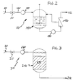
- FIG. 2 illustrates the use of an enzymatic catalyst for hydrolysis of urea.
- the apparatus 110 illustrated comprises mixing valve 111, conduit 120, pressure pump 130, stirring vessel 140, which contains the reaction mixture, circulation pump 150, filter element 160, and withdrawal conduit 112.
- the urea solution passes from storage tank 20 into stirring vessel 140, via pressure pump 130.
- the reaction solution circulates via circulation pump 150 and filter element 160.
- filter element 160 a partial stream leaves the system via conduit 112 while the enzymes are recycled via a filter membrane, such as a filter plug, a flat membrane, a coiled membrane, or a hollow fiber membrane, over which the flow passes tangentially.
- FIG. 3 illustrates an apparatus 210 for the hydrolysis of urea using enzymatic catalysis on a fixed bed.
- the urea solution is supplied from storage tank 20 via valve 211 and pump 220 and passes through fixed bed 230 situated in a reaction vessel 240 which consists of balls or fillers on which the enzyme Is immobilized.
- the hydrolyzed urea solution then leaves via a withdrawal conduit 212 to be introduced into the effluent.
- the reaction conduit utilized is an externally heated reaction tube having a nominal length of 6.1 meters (20 feet) and an inner diameter of 0.872 centimeters.
- the reaction tube is fitted with a high pressure piston pump and a back pressure valve to control the operating pressure of aqueous urea solution flowing through the tube.
- a solution of 200 grams urea in 1000 ml of water is fed through the reaction tube at a flow rate of 10.7 ml/min.
- the reaction tube is maintained at a temperature of 154°C (310°F) and the urea solution is passed through against a back-pressure of 113.9 at (1620 psi).
- the hydrolyzed solution is collected at the outlet of the reaction tube following the back pressure valve and analyzed for NH4 ⁇ ions or NH3 using a gas sensitive electrode.
- the hydrolyzed solution is found to contain a mean concentration of 1.7 moles per liter of NH4 ⁇ or NH3, which indicates a yield of 51% hydrolyzed product based on the initial urea concentration.
- Example 1 The process of Example 1 is repeated except two moles of formic acid per mole of urea is added to the solution.
- the pH of the solution is found to be 1.5. to provide a pH of 1.5.
- the hydrolyzed solution is found to contain a mean concentration of 2.8 moles of NH4 ⁇ or NH3 species per liter, which indicates a yield of 84% hydrolyzed product based on the initial urea concentration.
- the pH of the hydrolyzed solution is found to be 7.0 indicating a neutralization of the acid.
- Example 2 The procedure of Example 1 is repeated except one mole of sodium hydroxide is added per mole of urea.
- the pH of the solution is found to be 14.
- the hydrolzyed solution is found to contain a mean concentration of 3.0 moles of NH4 ⁇ or NH3 per liter, which indicates a yield of 90% hydrolyzed product based on the initial urea concentration.
- the pH of the hydrolyzed solution is found to be 11.5, indicating a neutralization of the base.
Landscapes
- Chemical & Material Sciences (AREA)
- Engineering & Computer Science (AREA)
- Organic Chemistry (AREA)
- Analytical Chemistry (AREA)
- Chemical Kinetics & Catalysis (AREA)
- Environmental & Geological Engineering (AREA)
- General Chemical & Material Sciences (AREA)
- Oil, Petroleum & Natural Gas (AREA)
- Health & Medical Sciences (AREA)
- Inorganic Chemistry (AREA)
- Biomedical Technology (AREA)
- Organic Low-Molecular-Weight Compounds And Preparation Thereof (AREA)
- Treating Waste Gases (AREA)
- Polyesters Or Polycarbonates (AREA)
- Separation Of Suspended Particles By Flocculating Agents (AREA)
- Cosmetics (AREA)
- Measuring Or Testing Involving Enzymes Or Micro-Organisms (AREA)
Abstract
Description
- The present invention relates to a process for the in-line hydrolysis of urea in order to facilitate the reduction of nitrogen oxides (NOx) in a combustion effluent. The reduction of nitrogen oxides is accomplished by utilizing the hydrolysis products of urea to minimize the generation of nitrous oxide (N₂O).
- Carbonaceous fuels can be made to burn more completely and with reduced emissions of carbon monoxide and unburned hydrocarbons when the oxygen concentrations and air/fuel ratios employed are those which permit high-flame temperatures. When fossil fuels are used in suspension fired boilers, such as large utility boilers, temperatures above about 1093°C (2000°F) and typically about 1204°C (2200°F) to about 1649°C (3000°F) are generated. Unfortunately, such high temperatures tend to cause the production of thermal NOx, the temperatures being so high that free radicals of oxygen and nitrogen are formed and chemically combine as nitrogen oxides. Nitrogen oxides can form even in circulating fluidized bed boilers which operate at temperatures which typically range from 704°C (1300°F) to 927°C (1700°F), as well as gas turbines and diesel engines.
- Nitrogen oxides are troublesome pollutants which are found in the combustion streams of boilers when fired as described above, and comprise a major irritant in smog. It is further believed that nitrogen oxides can undergo a process known as photochemical smog formation, through a series of reactions in the presence of some hydrocarbons. Moreover, nitrogen oxides comprise a significant contributor to acid rain and have been implicated as contributing to the undesirable depletion of the ozone layer. They may also impact on the warming of the atmosphere commonly referred to as "the greenhouse effect". Some or all of these effects are also believed to be attributable to nitrous oxide.
- Recently, many processes for the reduction of NOx in combustion effluents have been developed. They can generally be segregated into two basic categories: selective and non-selective. Among the selective processes, which are believed in the art to be the more desirable, there is a further division between selective catalytic reduction (SCR) and selective non-catalytic reduction (SNCR) processes. Although SCR processes are believed to be capable of achieving higher levels of nitrogen oxides reductions, SNCR processes are often preferred because of their greater economy and flexibility.
- SNCR processes, which are temperature dependent, generally utilize a nitrogenous substance such as urea or ammonia, as well as non-nitrogenous substances, and proceed in the gas phase by a complex series of free radical-mediated chemical reactions and involve various nitrogen, hydrogen, oxygen, and carbon-containing species and radicals. Unfortunately, it has recently been found that many nitrogenous substances, when introduced into a combustion effluent, can lead to the generation of nitrous oxide. Urea is generally considered the most desirable NOx reducing species because of its effectiveness and relatively broad temperature window, as well as its relatively non-toxic and environmentally benign nature. Urea breaks down into the amino radical (NH₂·), which is believed to be the moiety responsible for the reduction of NOx, but can also, under certain conditions, break down into cyanic or isocyanic acid according to the following reaction formula
2NH₂CONH₂ + OH· → 3NH₂· + HOCN (or HNCO) + H₂O + CO
The amido radical can then proceed to reduce NOx according to the following reaction pathway
NH₂· + NO → N₂ + H₂O
but the cyanic or isocyanic acid produced can then proceed further to form nitrous oxide and carbon monoxide or molecular nitrogen and carbon dioxide when combined with NOx according to the following set of reactions
HOCN (or HNCO) + OH· → NCO· + H₂O
NCO· + NO → N₂O + CO
NCO· + NO → N₂ + CO₂
When N₂O is formed, the effectiveness of urea is somewhat decreased, although NOx is being substantially reduced, because another pollutant species, N₂O, is sometimes discharged. - What is desired, therefore, is a process which enables the desired NOx reducing capabilities of urea to be exploited, as well as the stability and ease of handling of urea, without the generation of N₂O.
- Processes and compositions for the reduction of nitrogen oxides in an effluent from the combustion of a carbonaceous fuel have been developed extensively over recent years. With the increased attention to the health risks and environmental damage caused by agents such as smog and acid rain, it is expected that NOx reduction research will continue to be pursued.
- In an early application of the use of nitrogenous treatment agents to reduce NOx, Lyon in US-A-3,900,554, describes a process for reducing nitrogen monoxide (NO) from combustion effluents by introducing ammonia or certain "ammonia precursors" into the effluent at temperatures which range from 704°C to 1093°C (1300°F to 2000°F). In US-A-4,208,386, Arand, Muzio, and Sotter improve on the Lyon process by teaching the introduction of urea for NOx reduction in oxygen-rich effluents at temperatures in the range of 871°C to 1093°C (1600°F to 2000°F), when urea is introduced into the effluent alone, and 704°C (1300°F) to 871°C (1600°F) when urea is introduced with an ancillary reducing material. Arand, with Muzio and Teixeria, in US-A-4,325,924 also teach the introduction of urea into fuel-rich combustion effluents to reduce NOx at temperatures in excess of about 1038°C (1900°F).
- More recently, in a unique application of NOx reducing principles, Epperly, Peter-Hoblyn, Shulof, Jr., and Sullivan, in US-A-4,777,024 disclose a method for achieving substantial nitrogen oxides reductions while minimizing the production of so-called secondary pollutants, such as ammonia and carbon monoxide, through a multiple stage injection process. Moreover, Epperly, O'Leary, and Sullivan, in US-A-4,780,289 have disclosed a complementary process for achieving significant, and potentially maximized, NOx reductions while minimizing the production of secondary pollutants by utilizing the nitrogen oxides reduction versus effluent temperature curve of the treatment regimen being effected at each NOx reduction introduction in a combustion system. These inventions, though, focus mainly on minimizing the levels of ammonia and carbon monoxide while performing nitrogen oxides reductions and do not specifically address the generation of nitrous oxide.
- Schnell, in US-A-4,087,513 and US-A-4,168,299, discloses processes for the hydrolyzation of urea to ammonia and carbon dioxide to eliminate urea from the waste water stream formed during urea production. These processes involve introducing the waste water stream into a carbon dioxide recovery system, optionally in the presence of vanadium pentoxide. These patents, though, do not suggest the use of the urea hydrolyzation products for nitrogen oxides reduction, and especially not the use of hydrolyzation products ammonium carbamate, ammonium carbonate, ammonium bicarbonate, and ammonia for NOx reduction without generating N₂O.
- What is desired, therefore, is a system whereby nitrogen oxides reductions can be achieved while taking advantage of the advantages of the use of urea without the concommitant risk of generation of substantial amounts of N₂O.
- The present invention relates to a process for the reduction of nitrogen oxides in a combustion effluent, the process comprising an aqueous solution of urea, while flowing through a conduit of a nitrogen oxides reduction apparatus, being heated to a temperature and for a time effective to hydrolyze urea to produce hydrolysis products comprising ammonium carbamate, ammonium carbonate, ammonium bicarbonate, and ammonia, and introducing said hydrolysis products into the combustion effluent under conditions effective to reduce the nitrogen oxides concentration therein.
- In addition, the hydrolysis reaction can be improved by conducting it in an acidic or a basic environment or in the presence of certain catalysts or enzymes.
- The present invention further relates to an apparatus for treating a combustion effluent in accordance with the subject matter of
claim 20. - The objects of this invention will be described in the present invention better understood and its advantages more apparent in view of the following detailed description, especially when read with reference to the appended drawings wherein:
- FIGURE 1 is a schematic illustration of an apparatus for conducting urea hydrolysis under pressure with subsequent injection of the hydrolysis products into a combustion effluent;
- FIGURE 2 is a schematic illustration of an apparatus for the enzymatic hydrolysis of urea with suspended enzyme particles; and
- FIGURE 3 is a schematic illustration of an apparatus for the enzymatic hydrolysis of urea with the enzyme loaded on a fixed bed.
- As noted above, the present invention relates to the in-line hydrolysis of urea for the formation of hydrolysis products which can be introduced into a combustion effluent for the reduction of nitrogen oxides without the generation of nitrous oxide. The hydrolysis products produced include ammonium carbamate (NH₂COONH₄), ammonium carbonate ((NH₄)₂CO₃) and a mixture of ammonia (NH₃) and ammonium bicarbonate (NH₄HCO₃). Although each of these hydrolysis products is commercially available, it is more desirable to produce them by in-line hydrolysis because of the stability and relative safety of urea for transport and storage. Further, the solubility of ammonium carbonate and ammonium bicarbonate is substantially lower than that of urea, limiting their usefulness as a starting material. In the high temperature environment of a combustion effluent, these hydrolysis products can break down to form amino radicals which combine with nitrogen oxides as noted above to reduce them to N₂.
- Hydrolysis of urea can be performed in-line, for instance while the urea is being supplied to an injector or other introduction means to be introduced into a combustion effluent. This can be accomplished by passing an aqueous solution of urea, at a concentration of about 5% to about 45%, advantageously about 7% to about 15%, through a supply conduit (referred to as a reaction conduit or tube) and applying heat and pressure, maintaining the pressure above the partial pressure of the system NH₄·/NH₃/CO₂/H₂O at the selected temperature. The conduit can be any of the conventional tubes or pipes currently used to supply urea solutions to a combustion effluent in a NOx reducing apparatus. Thus the process can be practiced without significantly effecting the efficiency of current urea-mediated NOx reducing processes since it does not require substantial alteration or retrofitting of current installations.
- In order to hydrolyze the urea, the urea solution is raised to a temperature and for a time effective to hydrolyze the urea to ammonium carbamate, ammonium carbonate, ammonium bicarbonate, and ammonia. Generally, such temperatures are no greater than about 260°C (500°F), and preferably range from about 149°C (300°F) to about 232°C (450°F), more preferably about 163°C (325°F) to about 191°C (375°F) for a period of time of at least about three minutes in order to achieve substantial hydrolysis of the urea. Advantageously, hydrolysis need only proceed for a maximum of about six minutes for substantial completion. This reaction can be increased by also maintaining the urea solution under pressure, preferably pressure in excess of about 84.37 kilograms per square centimeter (at) (1,200 pounds per square inch (psi)), more preferably pressures pounds per square inch (psi)), more preferably pressures in excess of about 105.5 at (1,500 psi).
- Although hydrolysis by the application of heat and pressure is effective for urea hydrolysis, this hydrolysis reaction can be promoted (i.e., the efficiency increased) by the addition of a hydrolysis agent, such as one which functions by either raising or lowering the pH of the aqueous urea solution, together with or sequentially after application of heat (and pressure). In other words, a pH neutral urea solution can be made more alkaline or more acidic to promote hydrolysis.
- In order to hydrolyze urea under basic conditions, the pH of the aqueous urea solution is raised by the addition of an alkaline agent such as potassium hydroxide, sodium hydroxide, calcium hydroxide, calcium ammonia and ammonium bicarbonate. Although any increase in the pH will result in a greater rate of hydrolysis, it is desired for a substantial increase in hydrolysis that the pH be raised to at least about pH 11 or higher, even
pH 12 or higher. - When this basic hydrolysis process is being utilized, the temperature to which the urea solution is raised need not be as high as if heat were being utilized alone in order to achieve equivalent results. In this case, the temperature need only be raised to temperatures not exceeding about 204°C (400°F), especially about 138°C (280°F) to about 188°C (370°F) and preferably about 149°C (300°F) to about 177°C (350°F). Likewise, the pressure of the solution need only be raised to about 31.6 at (450 psi) to about 42.2 at (600 psi), preferably about 35.1 at (500 psi) to 39.4 at (560 psi). Advantageously, though, the temperatures and pressures applied when heat is used alone for hydrolysis are used when basic hydrolysis is employed, in order to provide significant increases in the efficiency of the hydrolysis reaction.
- To perform the acidic hydrolysis of urea, the pH of the aqueous urea solution is lowered, for instance by the addition of an acid or acid salt especially in solution, such as a buffered solution. Exemplary acids or acid salts include sulfuric acid, hydrochloric acid, formic acid, acetic acid, citric acid, ammonium hydrogen sulfate, or mixtures thereof. The use of formic acid and acetic acid are advantageous in this respect, because when combined with the hydrolysis product ammonia they can form the ammonium salts, ammonium acetate, and ammonium formate. These salts have been suggested as having a NOx reducing effect at temperatures below those of urea.
- Preferably, the pH of the solution when acidic hydrolysis is employed is brought to a level below about pH 5, most preferably below about pH 3 in order to substantially promote the hydrolysis of urea, although this is not critical. As was the case for basic hydrolysis, when acids are being added to the aqueous urea solution for hydrolysis the temperature need not be raised to those when heat is being used for hydrolysis alone. In the case of acidic hydrolysis, the temperature need only be raised to temperatures no greater than about 204°C (400°F), especially about 138°C (280°F) to about 189°C (370°F) and most preferably about 149°C (300°F) to about 177°C (350°F) in order to achieve results equivalents to those achieved with hydrolysis mediated by heat only. The pressure need only be raised to those used for basic hydrolysis. It is desired, though, that the application of heat and pressure be in the ranges discussed above for hydrolysis by heat alone in order to achieve increased hydrolysis efficiency.
- In performing either the alkaline or acidic hydrolysis of urea, the acidic or basic agent being added is admixed with the aqueous urea solution immediately before or during the application of heat and pressure, or immediately thereafter. The admixed solution is maintained for a period of about three to six minutes prior to introduction into the effluent, although the upper time limit is not considered critical.
- As noted above, urea hydrolysis can also be performed using, as the hydrolysis agent, suitable catalysts or enzymes, in either a heterogeneous or homogeneous system.
- In the heterogeneous embodiment, the catalyst is present on a fixed bed, for instance as a coating on the inside of the conduit through which the urea solution is flowing or on installations in the path of the flow; or in the form of catalyst particles suspended in the urea solution. Both the fixed bed and suspended catalyst particles preferably contain metals, especially metal oxides, metal salts, or mixtures thereof as the active catalyst ingredient. Advantageous suitable metals include copper, vanadium, iron, nickel, chromium, manganese, and their oxides and salts, especially their sulfate or chromate salts. In addition, a suspension of flue-ash or a suspension of oil black which can be found in vessels operated with heavy oil, can also be used as a heterogeneous catalyst.
- To achieve urea hydrolysis by means of a homogeneous catalyst, the aqueous urea solution can be admixed with catalyst in the form of water soluble metal salts, for instance, the sulfate or nitrate salts of metal such as copper and nickel. In this situation also filtrates of flue-ash suspension can also be utilized as catalyst.
- Urea hydrolysis can also be performed utilizing enzymes such as urease as a catalyst for the hydrolysis reaction. The enzyme can be added as it is or attached to an inert carrier particle in order to perform hydrolysis in the urea solution. The mixture of the enzyme with the aqueous urea solution is preferably circulated in a reactor with the hydrolysis products removed via a separation element. These hydrolysis products can then be introduced into the combustion effluent. Suitable separation elements include filter elements such as ultra filtration membranes. The enzyme can also be bound to in immobile phase which can be present in the reaction conduit, for instance, in the form of hollow fibers or other carrier particles.
- The hydrolysis products can be introduced into the effluent by suitable introduction means under conditions effective to reduce the effluent nitrogen oxides concentration in a selective, non-catalytic, gas-phase process. Suitable introduction means include injectors, such as those disclosed by Burton in US-A-4,842,834, or DeVita in US-A-4,915,036. One preferred type of injection means is an injection lance, especially a lance of the type disclosed by Peter-Hoblyn and Grimard in International Application PCT/EP89/00765, filed July 4, 1989, entitled "Lance-Type Injection Apparatus".
- Generally, the hydrolyzed urea solution of this invention is introduced into the effluent in an amount effective to elicit a reduction in the nitrogen oxides concentration in the effluent. Advantageously, the hydrolyzation products are introduced into the effluent in an amount sufficient to provide a molar ratio of the nitrogen contained in the solution to the baseline nitrogen oxides level (by which is meant the pretreatment level of NOx in the effluent) of about 1:5 to about 10:1. More preferably, the hydrolyzed solution is introduced into the effluent to provide a molar ratio of solution nitrogen to baseline nitrogen oxides level of about 1:3 to about 5:1, most preferably about 1:2 to about 3:1.
- The hydrolyzed urea solution produced by the process of this invention is preferably injected into the effluent gas stream at a point where the effluent is at a temperature above about 704°C (1300°F), more preferably above about 760°C (1400°F). Large industrial and circulating fluidized bed boilers of the types employed for utility power plants and other large facilities will typically have access only at limited points. In the most typical situations, the boiler interior in the area above the flame operates at temperatures which at full load approach 1204°C (2200°F), even 1260°C (2300°F). After subsequent heat exchange, the temperature will be lower, usually in the range between about 704°C (1300°F) and 1149°C (2100°F). At these temperatures, the hydrolyzation products produced in accordance with this invention can be effectively introduced to accomplish substantial reduction of nitrogen oxides in the effluent without the generation of significant amounts of nitrous oxide.
- Optionally, the hydrolyzation products can be enhanced by other compositions such as hexamethylenetetramine (HMTA), oxygenated hydrocarbons such as ethylene glycol, ammonium salts of organic acids such as ammonium acetate and ammonium benzoate, heterocyclic hydrocarbons having at least one cyclic oxygen such am furfural, molasses, sugar, 5- or 6-membered heterocyclic hydrocarbons having at least one cyclic nitrogen such as pyridine and pyrolidine, hydroxy amino hydrocarbons such as milk or skimmed milk, amino acids, proteins, and monoethanolamine and various other compounds which are disclosed as being effective at reducing nitrogen oxides in an effluent. These "enhancers", which are preferably present in an amount of about 0.5% to about 25% by weight when employed, function to lower the effluent temperatures at which hydrolyzed urea solution is most effective.
- Such enhancers as well as others which may be suitable are disclosed in, for instance, US-A-4,751,065; US-A-4,927,612; US-A-4,719,092; US-A-4,888,164; US-A-4,877,591; US-A-4,803,059; US-A-4,844,878; US-A-4,873,066; US-A-4,770,863; US-A-4,902,488; US-A-4,863,704; US-A-4,863,705; and International Patent Application entitled "Composition for Introduction into a High Temperature Environment", having Publication No. WO-A-8910182, filed in the names of Epperly, Sprague, and von Harpe on April 26, 1989.
- When the solution is introduced without a non-nitrogenous hydrocarbon component, it is preferably introduced at an effluent temperature of about 871°C (1600°F) to about 1149°C (2100°F), more preferably about 927°C (1700°F) to about 1149°C (2100°F). When the solution also comprises one of the enhancers discussed above, it is preferably introduced at an effluent temperature of about 704°C (1300°F) to about 954°C (1750°F), more preferably about 760°C (1400°F) to about 954°C (1750°F) or higher. These effluent temperatures at the point of introduction can be varied depending on the particular components of the treatment agent and other effluent conditions, such as the effluent oxygen level, as discussed in the referenced disclosures.
- The effluent into which the hydrolyzation products of this invention is injected is preferably oxygen-rich, meaning that there is an excess of oxygen in the effluent. Advantageously, the excess of oxygen is greater than about 1% by volume. Most preferably, the excess of oxygen is in the range of about 1% to about 12% or greater by volume.
- In a preferred embodiment of the invention, the in-line hydrolysis of urea is carried out by mixing an aqueous urea solution with the acid, base, or catalyst in a static mixer. This mixture is then heated, such as by passing through a heat exchanger or other suitable apparatus, and brought to the desired pressure and then passed to a decompression vessel in which the pressure is lowered, which causes the mixture to undergo separation into a liquid and gaseous phase. The liquid phase contains the liquid or liquid soluble hydrolysis products, ammonium carbamate, ammonium carbonate, and ammonium bicarbonate, which can then be introduced into the effluent, and the gaseous phase comprises the hydrolysis product ammonia, as well as carbon dioxide, which can also be introduced into the effluent. If the temperature of the mixture is brought to approximately room temperature (i.e. about 21.1°C (70°F)), the gases ammonia and carbon dioxide remain dissolved in the aqueous solution. Under these conditions the decompression vessel is not needed and the mixture itself can be directly introduced into the effluent.
- In a more preferred embodiment, the mixture of the aqueous urea solution with the acidic or basic agents or the catalyst is heated while passing through the conduits as described above to the injector with hydrolysis occurring in line and the hydrolyzed urea solution introduced directly into the effluent.
- The heat exchanger for heating the urea solution may be positioned in the effluent stream and as a result of this, the heat required for facilitating the urea hydrolysis reaction is withdrawn from the effluent to avoid the need for an independent heat source. Such heat exchanger preferably forms a unit together with the apparatus on which the injection means are arranged within the effluent stream. The heat exchanger at the same time cools the injector means, such as the injection lances, which is desirable at high combustion temperatures. The heat exchanger is preferably constructed in the form of a jacket around the injection lance. The heated and hydrolyzed urea solution is passed from the heat exchanger to a flash drum positioned outside the effluent, and the gaseous or liquid phase formed is separately supplied to the injectors of the injection lance, while pressurized air may optionally be added to the gaseous phase. In the latter embodiment, in particular if the hydrolysis is achieved by acidic hydrolysis, and any ammonia formed reacts with excess acid to form ammonium salts, the decompression vessel can be dispensed with and the hydrolyzed urea solution can be injected directly.
- When the hydrolysis is mediated by an enzymatic catalyst, the urea solution is recycled together with the enzyme to an intermediate stirring vessel or through a fixed bed of immobilized enzyme. The hydrolyzed products are then optionally withdrawn via a filter element and introduced into the effluent.
- A typical apparatus for achieving acidic, basic, or catalytic hydrolysis with introduction of the hydrolysis products into the effluent is illustrated in Figure 1. As shown, the illustrated apparatus 10 comprises a
urea storage tank 20, a hydrolyzing agent storage tank 30 (for the acid, base, or catalyst), a water supply line 11, a pressurizedair supply line 12, astatic mixer 40, aheat exchanger 50, areaction conduit 60, adecompression vessel 70, an entrainment jet 13, and an injection means 80, which extends into the effluent 100. Urea solution is supplied fromurea storage tank 20, hydrolyzation agent fromstorage tank 30, and dilution water are all supplied tostatic mixer 40, via pumps 14, 15, and 16. The resultant mixture is heated to the desired temperature inheat exchanger 50, passes throughreaction conduit 60, and is supplied to thedecompression vessel 70 via decompression valve 17. In thedecompression vessel 70, liquid phase separates from gaseous phase. The resulting gaseous phase is withdrawn viavalve 18 by means of entrainment jet 13, which is operated with pressurized air from pressurizedair supply line 12 throughpump 19. Whether the hydrolysis gases are entrained by the pressurized air or whether ambient air is entrained by the pressurized hydrolysis gases depends on the quantitative ratios and pressure conditions. The gas mixture (i.e., hydrolysis gases and air) and the liquid phase fromdecompression vessel 70 are each supplied to injection means such as two-phase nozzles arranged in the effluent stream and introduced into the effluent. - Figure 2 illustrates the use of an enzymatic catalyst for hydrolysis of urea. The
apparatus 110 illustrated comprises mixing valve 111,conduit 120,pressure pump 130, stirringvessel 140, which contains the reaction mixture,circulation pump 150, filter element 160, andwithdrawal conduit 112. After mixing the urea solution with the appropriate amount of enzyme fromenzyme conduit 120 via mixing valve 111, the urea solution passes fromstorage tank 20 into stirringvessel 140, viapressure pump 130. The reaction solution circulates viacirculation pump 150 and filter element 160. In filter element 160, a partial stream leaves the system viaconduit 112 while the enzymes are recycled via a filter membrane, such as a filter plug, a flat membrane, a coiled membrane, or a hollow fiber membrane, over which the flow passes tangentially. - Figure 3 illustrates an
apparatus 210 for the hydrolysis of urea using enzymatic catalysis on a fixed bed. In this apparatus the urea solution is supplied fromstorage tank 20 viavalve 211 and pump 220 and passes through fixedbed 230 situated in a reaction vessel 240 which consists of balls or fillers on which the enzyme Is immobilized. The hydrolyzed urea solution then leaves via awithdrawal conduit 212 to be introduced into the effluent. - The use of the present invention to achieve the hydrolysis of urea in an aqueous solution in order to facilitate the reduction of nitrogen oxides concentration in a combustion effluent without generating a substantial amount of N₂O is illustrated by reference to the following examples.
- The reaction conduit utilized is an externally heated reaction tube having a nominal length of 6.1 meters (20 feet) and an inner diameter of 0.872 centimeters. The reaction tube is fitted with a high pressure piston pump and a back pressure valve to control the operating pressure of aqueous urea solution flowing through the tube.
- A solution of 200 grams urea in 1000 ml of water is fed through the reaction tube at a flow rate of 10.7 ml/min. The reaction tube is maintained at a temperature of 154°C (310°F) and the urea solution is passed through against a back-pressure of 113.9 at (1620 psi). The hydrolyzed solution is collected at the outlet of the reaction tube following the back pressure valve and analyzed for NH₄· ions or NH₃ using a gas sensitive electrode. The hydrolyzed solution is found to contain a mean concentration of 1.7 moles per liter of NH₄· or NH₃, which indicates a yield of 51% hydrolyzed product based on the initial urea concentration.
- The process of Example 1 is repeated except two moles of formic acid per mole of urea is added to the solution. The pH of the solution is found to be 1.5. to provide a pH of 1.5. The hydrolyzed solution is found to contain a mean concentration of 2.8 moles of NH₄· or NH₃ species per liter, which indicates a yield of 84% hydrolyzed product based on the initial urea concentration. In addition, the pH of the hydrolyzed solution is found to be 7.0 indicating a neutralization of the acid.
- The procedure of Example 1 is repeated except one mole of sodium hydroxide is added per mole of urea. The pH of the solution is found to be 14. The hydrolzyed solution is found to contain a mean concentration of 3.0 moles of NH₄· or NH₃ per liter, which indicates a yield of 90% hydrolyzed product based on the initial urea concentration. In addition, the pH of the hydrolyzed solution is found to be 11.5, indicating a neutralization of the base.
Claims (25)
- A process for the reduction of nitrogen oxides in a combustion effluent, the process comprising an aqueous solution of urea, while flowing through a conduit of a nitrogen oxides reduction apparatus, being heated to a temperature and for a time effective to hydrolyze urea to produce hydrolysis products comprising ammonium carbamate, ammonium carbonate, ammonium bicarbonate, and ammonia, and introducing said hydrolysis products into the combustion effluent under conditions effective to reduce the nitrogen oxides concentration therein.
- The process of claim 1, wherein the urea solution is heated to a temperature no greater than about 260°C (500°F).
- The process of claim 1, wherein the urea solution is subjected to a pressure in excess of about 84.37 kg/cm² (1200 pounds per square inch).
- The process of claim 3, wherein the pH of the urea solution is increased to at least about 11.
- The process of claim 4, wherein the urea solution is admixed with an alkaline agent selected from the group consisting of potassium hydroxide, sodium hydroxide, calcium hydroxide, calcium oxide, magnesium oxide, semicalcined dolomite, ammonia, ammonium bicarbonate, ammonium carbamate, ammonium carbonate, and mixtures thereof.
- The process of claim 1, wherein the pH of the urea solution is decreased by admixing with an acidic agent.
- The process of claim 6, wherein the pH of the urea solution is decreased to no greater than about 5.
- The process of claim 7, wherein the urea solution is admixed with an acidic agent selected fro the group consisting of sulfuric acid, hydrochloric acid, formic acid, acetic acid, citric acid, ammonium hydrogen sulfate, ammonium bisulfate, and mixtures thereof.
- The process of claim 1, wherein the urea solution is contacted with a catalyst or enzyme for the hydrolysis of urea.
- The process of claim 9, wherein said catalyst is selected from the group consisting of metals, metal oxides, metal salts, and mixtures thereof.
- The process according to claim 10, wherein the catalytic hydrolysis occurs in a fixed bed reactor.
- The process according to claim 11, wherein the catalytic hydrolysis occurs in a pipe covered with a catalyst or in catalyst-bearing installations in the reaction path.
- The process according to claim 10, wherein the catalytic hydrolysis produced by means of suspended catalyst particles.
- The process according to claim 9, wherein said catalyst is a suspension of flue ash or oil black.
- The process of claim 9, wherein said enzyme is urease.
- The process according to claim 15, wherein the urea solution is passed through at least one suitable reactor, whereby the urea solution is circulated for hydrolysis together with an enzyme, the hydrolysis products are removed from the reactor via a separation element and are introduced into the effluent.
- The process according to claim 16, wherein the enzyme is immobilized on inert carrier particles.
- The process according to claim 16, wherein the separation element is a filter element suitable for separating enzyme particles.
- The process according to claim 16, wherein the urea solution is passed through an immobile phase covered with enzymes.
- An apparatus (10) for treating a combustion effluent by the in-line preparation of urea hydrolysis products and the introduction thereof into the effluent, comprisinga) a boiler which comprises a passage for the flow of an effluent from the combustion of a carbonaceous fuel (100);b) a urea supply means (20, 14) which supplies a flow of an aqueous solution which comprises urea;c) a conduit (60) in operative connection with said supply means, wherein said supply means supplies a flow of a urea solution through said conduit such that the flow of urea solution is under pressure in at least a portion of said conduit;d) heating means (50) for heating the urea solution as it flows through at least a portion of said conduit; ande) introducing means (80) for introducing the urea solution into said effluent passage, wherein said means for introducing is in operative connection with said conduit such that the urea solution flows from said conduit through said introducing means and into said passage.
- The apparatus of claim 20, wherein said means for heating comprises a heat exchanger, at least a portion of which is positioned in said passage.
- The apparatus of claim 20, which further comprises a hydrolyzation agent supply means and a mixing means for mixing the urea solution and the hydrolyzation promoting agent, said mixing means disposed such that the urea solution and hydrolyzation promoting agent are fed thereinto by said urea supply means and said hydrolyzation supply means and the mixed urea solution and hydrolyzation promoting agent fed to said conduit.
- The apparatus of claim 22, which further comprises a decompression vessel disposed between said conduit and said introducing means to lower the pressure of the urea solution/hydrolyzation promoting agent mixture to separate the mixture into a liquid phase and a gaseous phase.
- The apparatus of claim 21, wherein said heat exchanger cooperates with said injector means to cool said injector means.
- The apparatus of claim 20, wherein said introduction means comprises at least one injector means, in which a two phase mixture of the hydrolyzed urea solution and air is formed, the hydrolyzed solution being dispersed into small droplets on injection from the injection means.
Applications Claiming Priority (3)
| Application Number | Priority Date | Filing Date | Title |
|---|---|---|---|
| US561154 | 1983-12-13 | ||
| US07/561,154 US5240688A (en) | 1990-08-01 | 1990-08-01 | Process for the in-line hydrolysis of urea |
| PCT/EP1991/001450 WO1992002291A1 (en) | 1990-08-01 | 1991-08-01 | Process for the in-line hydrolysis of urea |
Publications (2)
| Publication Number | Publication Date |
|---|---|
| EP0542792A1 EP0542792A1 (en) | 1993-05-26 |
| EP0542792B1 true EP0542792B1 (en) | 1995-11-08 |
Family
ID=24240855
Family Applications (2)
| Application Number | Title | Priority Date | Filing Date |
|---|---|---|---|
| EP91913756A Expired - Lifetime EP0542792B1 (en) | 1990-08-01 | 1991-08-01 | Process for the in-line hydrolysis of urea |
| EP91916169A Expired - Lifetime EP0495089B1 (en) | 1990-08-01 | 1991-08-01 | Nitrogen oxides reduction using a urea hydrolysate |
Family Applications After (1)
| Application Number | Title | Priority Date | Filing Date |
|---|---|---|---|
| EP91916169A Expired - Lifetime EP0495089B1 (en) | 1990-08-01 | 1991-08-01 | Nitrogen oxides reduction using a urea hydrolysate |
Country Status (8)
| Country | Link |
|---|---|
| US (2) | US5240688A (en) |
| EP (2) | EP0542792B1 (en) |
| AT (2) | ATE129925T1 (en) |
| AU (1) | AU8297991A (en) |
| CA (2) | CA2063811C (en) |
| DE (2) | DE69114503T2 (en) |
| FI (1) | FI930377A7 (en) |
| WO (2) | WO1992002291A1 (en) |
Cited By (1)
| Publication number | Priority date | Publication date | Assignee | Title |
|---|---|---|---|---|
| CN104477939A (en) * | 2014-10-28 | 2015-04-01 | 河南骏化发展股份有限公司 | Low-pressure hydrolysis technology |
Families Citing this family (79)
| Publication number | Priority date | Publication date | Assignee | Title |
|---|---|---|---|---|
| US5441713A (en) * | 1988-04-29 | 1995-08-15 | Nalco Fuel Tech | Hardness suppression in urea solutions |
| US6051040A (en) * | 1988-12-28 | 2000-04-18 | Clean Diesel Technologies, Inc. | Method for reducing emissions of NOx and particulates from a diesel engine |
| US5543123A (en) * | 1990-08-01 | 1996-08-06 | Nalco Fuel Tech | Low pressure formation of a urea hydrolysate for nitrogen oxides reduction |
| US5342599A (en) * | 1990-09-14 | 1994-08-30 | Cummins Power Generation, Inc. | Surface stabilized sources of isocyanic acid |
| US5281403B1 (en) * | 1991-09-27 | 1996-06-11 | Noell Inc | Method for converting urea to ammonia |
| FR2682110B1 (en) * | 1991-10-02 | 1995-05-24 | Atta | PERFLUOROALKYL AMPHIPHILIC LIGANDS, THEIR METAL COMPLEXES AND THEIR USES IN PREPARATIONS FOR THERAPEUTIC USE. |
| DE59307293D1 (en) * | 1992-02-10 | 1997-10-16 | Man Nutzfahrzeuge Ag | Device for the catalytic NOX reduction |
| TW229225B (en) * | 1992-05-06 | 1994-09-01 | Malco Fuel Tech | |
| US5536482A (en) * | 1992-10-13 | 1996-07-16 | Nalco Fuel Tech | Process for pollution control |
| US5489419A (en) * | 1992-10-13 | 1996-02-06 | Nalco Fuel Tech | Process for pollution control |
| US5404841A (en) * | 1993-08-30 | 1995-04-11 | Valentine; James M. | Reduction of nitrogen oxides emissions from diesel engines |
| WO1995009810A1 (en) * | 1993-10-06 | 1995-04-13 | Nalco Fuel Tech | Low pressure formation of a urea hydrolysate for nitrogen oxides reduction |
| US5489420A (en) * | 1994-03-10 | 1996-02-06 | Nalco Fuel Tech | Nitrogen oxides reducing agent and a phosphate |
| US5658547A (en) * | 1994-06-30 | 1997-08-19 | Nalco Fuel Tech | Simplified efficient process for reducing NOx, SOx, and particulates |
| DE4425420A1 (en) * | 1994-07-19 | 1995-07-27 | Daimler Benz Ag | Denitrification of engine exhaust gas with ammonia generated as required |
| AU3495195A (en) * | 1994-08-26 | 1996-03-22 | Us Sulfamate, Inc. | Molten urea dehydrate derived compositions |
| GB9513989D0 (en) * | 1995-07-08 | 1995-09-06 | Brunner Mond & Co Ltd | Treatment of flue gases |
| FR2740356B1 (en) * | 1995-10-31 | 1997-11-28 | Rhone Poulenc Chimie | PROCESS FOR THE TREATMENT OF FUMES WITH CARBONATE AND / OR WET SODIUM BICARBONATE |
| US5992141A (en) * | 1996-04-02 | 1999-11-30 | Kleen Air Systems, Inc. | Ammonia injection in NOx control |
| US5681536A (en) * | 1996-05-07 | 1997-10-28 | Nebraska Public Power District | Injection lance for uniformly injecting anhydrous ammonia and air into a boiler cavity |
| US20050019363A1 (en) * | 1996-09-30 | 2005-01-27 | Blount David H. | Hydrolyzed urea condensate fertilizer, fungicide and insecticide |
| US6077491A (en) | 1997-03-21 | 2000-06-20 | Ec&C Technologies | Methods for the production of ammonia from urea and/or biuret, and uses for NOx and/or particulate matter removal |
| US6361754B1 (en) * | 1997-03-27 | 2002-03-26 | Clean Diesel Technologies, Inc. | Reducing no emissions from an engine by on-demand generation of ammonia for selective catalytic reduction |
| US5809775A (en) * | 1997-04-02 | 1998-09-22 | Clean Diesel Technologies, Inc. | Reducing NOx emissions from an engine by selective catalytic reduction utilizing solid reagents |
| US5976475A (en) * | 1997-04-02 | 1999-11-02 | Clean Diesel Technologies, Inc. | Reducing NOx emissions from an engine by temperature-controlled urea injection for selective catalytic reduction |
| JPH11171535A (en) * | 1997-12-05 | 1999-06-29 | Mitsubishi Heavy Ind Ltd | Method for generating ammonia and exhaust gas treatment using ammonia generated therewith. |
| EP0969915A1 (en) * | 1997-12-12 | 2000-01-12 | FEV Motorentechnik GmbH | Method for reducing nitrogen oxides in exhaust gases containing oxygen, especially exhaust gases from internal combustion engines |
| WO1999056858A2 (en) * | 1998-04-30 | 1999-11-11 | Siemens Aktiengesellschaft | Method and device for catalytic reduction of nitrogen oxide |
| ITMI981155A1 (en) * | 1998-05-25 | 1999-11-25 | Siirtec Nigi S P A | PROCESS FOR THE PRODUCTION OF AMMONIA BY HYDROLYSIS OF THE UREA |
| US6093380A (en) * | 1998-10-16 | 2000-07-25 | Siirtec Nigi, S.P.A. | Method and apparatus for pollution control in exhaust gas streams from fossil fuel burning facilities |
| US6146605A (en) * | 1999-07-26 | 2000-11-14 | Hera, Llc | Combined SCR/SNCR process |
| US6403046B1 (en) | 1999-07-26 | 2002-06-11 | Hera, Llc | Pollution control systems using urea and ammonia for the control of emissions from the flue gas of fossil fuel burning facilities |
| US6511644B1 (en) | 2000-08-28 | 2003-01-28 | The Chemithon Corporation | Method for removing contaminants in reactors |
| US6436359B1 (en) | 2000-10-25 | 2002-08-20 | Ec&C Technologies, Inc. | Method for controlling the production of ammonia from urea for NOx scrubbing |
| US6761868B2 (en) * | 2001-05-16 | 2004-07-13 | The Chemithon Corporation | Process for quantitatively converting urea to ammonia on demand |
| JP3820163B2 (en) * | 2002-02-22 | 2006-09-13 | 三井化学株式会社 | Urea concentration measuring method and apparatus |
| US20030211024A1 (en) * | 2002-05-10 | 2003-11-13 | Wojichowski David Lee | Methods of converting urea to ammonia for SCR, SNCR and flue gas conditioning |
| US6887284B2 (en) * | 2002-07-12 | 2005-05-03 | Dannie B. Hudson | Dual homogenization system and process for fuel oil |
| KR100498083B1 (en) * | 2002-08-27 | 2005-07-01 | 강희수 | Carrying board of grey yarn beam |
| US6887449B2 (en) * | 2002-11-21 | 2005-05-03 | The Chemithon Corporation | Method of quantitatively producing ammonia from urea |
| EP1742871A4 (en) * | 2004-05-05 | 2011-11-30 | Robert K Graupner | Guanidine based composition and system for same |
| WO2006087553A1 (en) * | 2005-02-16 | 2006-08-24 | Imi Vision Limited | Exhaust as treatment |
| EP1856386A1 (en) * | 2005-02-16 | 2007-11-21 | Imi Vision Limited | Exhaust gas treatment |
| US7985280B2 (en) * | 2007-02-20 | 2011-07-26 | Hitachi Power Systems America, Ltd. | Separation of aqueous ammonia components for NOx reduction |
| US20080267837A1 (en) * | 2007-04-27 | 2008-10-30 | Phelps Calvin E | Conversion of urea to reactants for NOx reduction |
| AU2008274985A1 (en) * | 2007-07-12 | 2009-01-15 | Powerspan Corp | Scrubbing of ammonia with urea ammonium nitrate solution |
| EP2190781A2 (en) * | 2007-08-24 | 2010-06-02 | Powerspan Corp. | Method and apparatus for producing ammonium carbonate from urea |
| US20090148370A1 (en) * | 2007-12-06 | 2009-06-11 | Spencer Iii Herbert W | Process to produce ammonia from urea |
| CA2730029A1 (en) * | 2008-07-29 | 2010-02-04 | Powerspan Corp. | Using raman spectroscopy to control carbonate / bicarbonate concentrations |
| CN102884292B (en) * | 2010-04-02 | 2016-01-20 | 俄亥俄州立大学 | Selective catalytic reduction by electrolysis of urea |
| US8562929B2 (en) | 2010-04-02 | 2013-10-22 | Ohio University | Selective catalytic reduction via electrolysis of urea |
| WO2012104205A1 (en) * | 2011-02-04 | 2012-08-09 | Paul Scherrer Institut | Ammonia generator converting liquid ammonia precursor solutions to gaseous ammonia for denox-applications using selective catalytic reduction of nitrogen oxides |
| WO2012123380A2 (en) | 2011-03-11 | 2012-09-20 | Puregeneration (Uk) Ltd | Production and use of cyanoguanidine and cyanamide |
| US8518354B2 (en) * | 2011-07-29 | 2013-08-27 | Deere & Company | Diesel exhaust fluid formulation having a high ammonium content and a low freezing point |
| CN102553412A (en) * | 2012-02-10 | 2012-07-11 | 山东大学 | Method for denitrifying flue gas by using amino reducing agent with high reaction activity |
| DE102014204307A1 (en) | 2013-03-19 | 2014-09-25 | Ford Global Technologies, Llc | Method and arrangement for the treatment of exhaust gases of an internal combustion engine |
| EP2926886A1 (en) * | 2014-04-01 | 2015-10-07 | Inergy Automotive Systems Research (Société Anonyme) | System comprising a decomposition unit for use on board of a vehicle |
| US9586831B2 (en) | 2014-06-09 | 2017-03-07 | Wahlco, Inc. | Urea to ammonia process |
| CN106807193A (en) * | 2015-12-02 | 2017-06-09 | 昆山市三维换热器有限公司 | A kind of flue-gas denitration process system |
| US10844763B2 (en) | 2017-03-10 | 2020-11-24 | R. F. Macdonald Co. | Process for direct urea injection with selective catalytic reduction (SCR) for NOx reduction in hot gas streams and related systems and assemblies |
| CN106986434B (en) * | 2017-04-20 | 2022-12-02 | 中国科学院生态环境研究中心 | Pretreatment method of antibiotic production wastewater |
| US10683787B2 (en) | 2018-11-08 | 2020-06-16 | Faurecia Emissions Control Technologies, Usa, Llc | Automotive exhaust aftertreatment system having onboard ammonia reactor with hybrid heating |
| US10767529B2 (en) | 2018-11-08 | 2020-09-08 | Faurecia Emissions Control Technologies, Usa, Llc | Automotive exhaust aftertreatment system having onboard ammonia reactor with heated doser |
| US10876454B2 (en) | 2018-11-08 | 2020-12-29 | Faurecia Emissions Control Technologies, Usa, Llc | Automotive exhaust aftertreatment system with multi-reductant injection and doser controls |
| US11193413B2 (en) | 2019-12-12 | 2021-12-07 | Faurecia Emissions Control Technologies, Usa, Llc | Exhaust aftertreatment system with virtual temperature determination and control |
| CN111135714A (en) * | 2020-01-15 | 2020-05-12 | 安徽晨晰洁净科技有限公司 | Method for using ammonium bicarbonate as SCR denitration reducing agent |
| US11319853B2 (en) | 2020-03-31 | 2022-05-03 | Faurecia Emissions Control Technologies, Usa, Llc | Automotive exhaust aftertreatment system with doser |
| US11022014B1 (en) | 2020-04-28 | 2021-06-01 | Faurecia Emissions Control Technologies, Usa, Llc | Exhaust aftertreatment system with heated flash-boiling doser |
| US11092054B1 (en) | 2020-04-29 | 2021-08-17 | Faurecia Emissions Control Technologies, Usa, Llc | Flash-boiling doser with thermal transfer helix |
| US11511239B2 (en) | 2020-04-29 | 2022-11-29 | Faurecia Emissions Control Technologies, Usa, Llc | Heated flash-boiling doser with integrated helix |
| US11384667B2 (en) | 2020-05-29 | 2022-07-12 | Faurecia Emissions Control Technologies, Usa, Llc | Exhaust aftertreatment system with heated dosing control |
| US11225894B1 (en) | 2020-06-30 | 2022-01-18 | Faurecia Emissions Control Technologies, Usa, Llc | Exhaust aftertreatment system with thermally controlled reagent doser |
| CN112354487B (en) * | 2020-11-06 | 2022-10-14 | 李东田 | Preparation method of ammonium carbonate feed gas |
| CN112661172B (en) * | 2020-12-23 | 2024-12-20 | 中国华电科工集团有限公司 | A system and method for producing ammonia by heterogeneous catalytic hydrolysis of SCR denitrification urea |
| CN114405450A (en) * | 2022-02-23 | 2022-04-29 | 西安热工研究院有限公司 | Filling type urea catalytic hydrolysis device |
| CN115057454B (en) * | 2022-06-28 | 2023-06-23 | 江苏国瑞特环保工程技术有限公司 | High alkaline environment improvement type urea hydrolysis ammonia production system |
| CN117654265A (en) * | 2023-10-25 | 2024-03-08 | 国能神皖池州发电有限责任公司 | A method and system for preparing ammonia gas by hydrolysis of urea for denitration |
| CN117358032A (en) * | 2023-10-31 | 2024-01-09 | 华能巢湖发电有限责任公司 | A stable denitrification agent and its application |
| WO2025218930A1 (en) * | 2024-04-18 | 2025-10-23 | Casale Sa | A process for treating the waste water of a urea production plant |
Family Cites Families (20)
| Publication number | Priority date | Publication date | Assignee | Title |
|---|---|---|---|---|
| DE200617C (en) * | ||||
| US3900554A (en) * | 1973-03-16 | 1975-08-19 | Exxon Research Engineering Co | Method for the reduction of the concentration of no in combustion effluents using ammonia |
| US4208386A (en) * | 1976-03-03 | 1980-06-17 | Electric Power Research Institute, Inc. | Urea reduction of NOx in combustion effluents |
| JPS5314662A (en) * | 1976-07-28 | 1978-02-09 | Hitachi Ltd | Method for decreasing nitrogen oxides concentration of combustion exhaust gas |
| US4087513A (en) * | 1977-08-12 | 1978-05-02 | Olin Corporation | Method of hydrolyzing urea contained in waste water streams |
| US4325924A (en) * | 1977-10-25 | 1982-04-20 | Electric Power Research Institute, Inc. | Urea reduction of NOx in fuel rich combustion effluents |
| JPS5486020A (en) * | 1977-12-21 | 1979-07-09 | Okubo Yoshinori | Combustion method of hydrocarbon fuel |
| US4168299A (en) * | 1978-03-20 | 1979-09-18 | Olin Corporation | Catalytic method for hydrolyzing urea |
| NL8102391A (en) * | 1981-05-15 | 1982-12-01 | Unie Van Kunstmestfab Bv | METHOD FOR EXTRACTING VALUABLE COMPONENTS FROM THE WASTE STREAMS OBTAINED IN THE URE PREPARATION. |
| NL8105027A (en) * | 1981-11-06 | 1983-06-01 | Stamicarbon | Converting gaseous urea (deriv.) into carbon di:oxide and ammonia - by contacting with catalyst in presence of water vapour |
| US4626417A (en) * | 1983-09-29 | 1986-12-02 | Union Oil Company Of California | Methods for chemically reducing nitrogen oxides |
| US4780289A (en) * | 1987-05-14 | 1988-10-25 | Fuel Tech, Inc. | Process for nitrogen oxides reduction and minimization of the production of other pollutants |
| US4777024A (en) * | 1987-03-06 | 1988-10-11 | Fuel Tech, Inc. | Multi-stage process for reducing the concentration of pollutants in an effluent |
| JPS6419665A (en) * | 1987-07-14 | 1989-01-23 | Jeol Ltd | Ion beam device |
| JPH03503735A (en) * | 1988-02-02 | 1991-08-22 | ジョーンズ,デイル ゴードン | Two-stage boiler injection method and device for the purpose of reducing nitrogen oxides |
| AT390208B (en) * | 1988-05-09 | 1990-04-10 | Waagner Biro Ag | METHOD FOR REMOVING NITROGEN OXIDES |
| DE3830045C2 (en) * | 1988-09-03 | 1993-09-30 | Bayer Ag | Process for the reduction of nitrogen oxides contained in exhaust gases by means of a zeolite-containing catalyst |
| JPH02191528A (en) * | 1989-01-20 | 1990-07-27 | Babcock Hitachi Kk | Denitrification device with solid reducing agent utilized therefor |
| US4987513A (en) * | 1989-04-12 | 1991-01-22 | Shelley Edwin F | Apparatus and method for selectively delaying the connection of an electrical supply voltage to an electrical load |
| US4997631A (en) * | 1990-03-07 | 1991-03-05 | Fuel Tech, Inc. | Process for reducing nitrogen oxides without generating nitrous oxide |
-
1990
- 1990-08-01 US US07/561,154 patent/US5240688A/en not_active Expired - Fee Related
-
1991
- 1991-08-01 AT AT91913756T patent/ATE129925T1/en not_active IP Right Cessation
- 1991-08-01 DE DE69114503T patent/DE69114503T2/en not_active Expired - Fee Related
- 1991-08-01 EP EP91913756A patent/EP0542792B1/en not_active Expired - Lifetime
- 1991-08-01 CA CA002063811A patent/CA2063811C/en not_active Expired - Fee Related
- 1991-08-01 FI FI930377A patent/FI930377A7/en not_active Application Discontinuation
- 1991-08-01 WO PCT/EP1991/001450 patent/WO1992002291A1/en not_active Ceased
- 1991-08-01 WO PCT/US1991/005461 patent/WO1992002450A1/en not_active Ceased
- 1991-08-01 EP EP91916169A patent/EP0495089B1/en not_active Expired - Lifetime
- 1991-08-01 AU AU82979/91A patent/AU8297991A/en not_active Abandoned
- 1991-08-01 AT AT91916169T patent/ATE134155T1/en not_active IP Right Cessation
- 1991-08-01 DE DE69117163T patent/DE69117163T2/en not_active Expired - Fee Related
- 1991-08-01 CA CA002088576A patent/CA2088576A1/en not_active Abandoned
-
1992
- 1992-02-26 US US07/820,907 patent/US5399325A/en not_active Expired - Fee Related
Cited By (2)
| Publication number | Priority date | Publication date | Assignee | Title |
|---|---|---|---|---|
| CN104477939A (en) * | 2014-10-28 | 2015-04-01 | 河南骏化发展股份有限公司 | Low-pressure hydrolysis technology |
| CN104477939B (en) * | 2014-10-28 | 2017-01-18 | 河南骏化发展股份有限公司 | Low-pressure hydrolysis technology |
Also Published As
| Publication number | Publication date |
|---|---|
| EP0542792A1 (en) | 1993-05-26 |
| AU8297991A (en) | 1992-03-02 |
| WO1992002291A1 (en) | 1992-02-20 |
| EP0495089B1 (en) | 1996-02-14 |
| FI930377A0 (en) | 1993-01-29 |
| FI930377L (en) | 1993-01-29 |
| DE69117163T2 (en) | 1996-09-05 |
| US5399325A (en) | 1995-03-21 |
| US5240688A (en) | 1993-08-31 |
| ATE134155T1 (en) | 1996-02-15 |
| CA2063811C (en) | 2000-05-09 |
| DE69117163D1 (en) | 1996-03-28 |
| DE69114503T2 (en) | 1996-05-02 |
| DE69114503D1 (en) | 1995-12-14 |
| CA2063811A1 (en) | 1992-02-02 |
| CA2088576A1 (en) | 1992-02-02 |
| ATE129925T1 (en) | 1995-11-15 |
| FI930377A7 (en) | 1993-01-29 |
| WO1992002450A1 (en) | 1992-02-20 |
| EP0495089A1 (en) | 1992-07-22 |
| EP0495089A4 (en) | 1993-03-10 |
Similar Documents
| Publication | Publication Date | Title |
|---|---|---|
| US5240688A (en) | Process for the in-line hydrolysis of urea | |
| US5543123A (en) | Low pressure formation of a urea hydrolysate for nitrogen oxides reduction | |
| EP0287224B1 (en) | Methods of removing NOx and SOx emissions from combustion systems using nitrogenous compounds | |
| EP0306515B1 (en) | Multi-stage process for reducing the concentration of pollutants in an effluent | |
| EP0524953B1 (en) | Process for reducing nitrogen oxides without generating nitrous oxide | |
| EP0564550B1 (en) | Process and apparatus for the thermal decomposition of nitrous oxide | |
| EP0392116A1 (en) | Process for the removal of acid forming gases from exhaust gases | |
| US5047219A (en) | Hybrid process for nitrogen oxides reduction | |
| JPH02501715A (en) | Multi-stage process for reducing pollutant concentration in exhaust gas | |
| US4873066A (en) | Low temperature process for the reduction of nitrgen oxides in an effluent | |
| WO1995009810A1 (en) | Low pressure formation of a urea hydrolysate for nitrogen oxides reduction | |
| WO1993022047A1 (en) | Process for the catalytic reduction of nitrogen oxides | |
| AU8517791A (en) | Nitrogen oxides reduction using a urea hydrolysate | |
| WO1994009896A1 (en) | Process and composition for sorbent reduction of n2o | |
| WO1988007497A1 (en) | Process for the reduction of nitrogen oxides in an effluent using a heterocyclic hydrocarbon |
Legal Events
| Date | Code | Title | Description |
|---|---|---|---|
| PUAI | Public reference made under article 153(3) epc to a published international application that has entered the european phase |
Free format text: ORIGINAL CODE: 0009012 |
|
| 17P | Request for examination filed |
Effective date: 19930224 |
|
| AK | Designated contracting states |
Kind code of ref document: A1 Designated state(s): AT BE CH DE DK ES FR GB GR IT LI LU NL SE |
|
| RAP1 | Party data changed (applicant data changed or rights of an application transferred) |
Owner name: NALCO FUEL TECH GMBH |
|
| 17Q | First examination report despatched |
Effective date: 19940601 |
|
| GRAA | (expected) grant |
Free format text: ORIGINAL CODE: 0009210 |
|
| AK | Designated contracting states |
Kind code of ref document: B1 Designated state(s): AT BE CH DE DK ES FR GB GR IT LI LU NL SE |
|
| PG25 | Lapsed in a contracting state [announced via postgrant information from national office to epo] |
Ref country code: LI Effective date: 19951108 Ref country code: IT Free format text: LAPSE BECAUSE OF FAILURE TO SUBMIT A TRANSLATION OF THE DESCRIPTION OR TO PAY THE FEE WITHIN THE PRESCRIBED TIME-LIMIT;WARNING: LAPSES OF ITALIAN PATENTS WITH EFFECTIVE DATE BEFORE 2007 MAY HAVE OCCURRED AT ANY TIME BEFORE 2007. THE CORRECT EFFECTIVE DATE MAY BE DIFFERENT FROM THE ONE RECORDED. Effective date: 19951108 Ref country code: DK Effective date: 19951108 Ref country code: FR Effective date: 19951108 Ref country code: ES Free format text: THE PATENT HAS BEEN ANNULLED BY A DECISION OF A NATIONAL AUTHORITY Effective date: 19951108 Ref country code: CH Effective date: 19951108 Ref country code: GR Free format text: LAPSE BECAUSE OF FAILURE TO SUBMIT A TRANSLATION OF THE DESCRIPTION OR TO PAY THE FEE WITHIN THE PRESCRIBED TIME-LIMIT Effective date: 19951108 Ref country code: NL Free format text: LAPSE BECAUSE OF FAILURE TO SUBMIT A TRANSLATION OF THE DESCRIPTION OR TO PAY THE FEE WITHIN THE PRESCRIBED TIME-LIMIT Effective date: 19951108 Ref country code: BE Effective date: 19951108 |
|
| REF | Corresponds to: |
Ref document number: 129925 Country of ref document: AT Date of ref document: 19951115 Kind code of ref document: T |
|
| REF | Corresponds to: |
Ref document number: 69114503 Country of ref document: DE Date of ref document: 19951214 |
|
| PG25 | Lapsed in a contracting state [announced via postgrant information from national office to epo] |
Ref country code: SE Effective date: 19960208 |
|
| NLV1 | Nl: lapsed or annulled due to failure to fulfill the requirements of art. 29p and 29m of the patents act | ||
| EN | Fr: translation not filed | ||
| REG | Reference to a national code |
Ref country code: CH Ref legal event code: PL |
|
| PG25 | Lapsed in a contracting state [announced via postgrant information from national office to epo] |
Ref country code: LU Free format text: LAPSE BECAUSE OF NON-PAYMENT OF DUE FEES Effective date: 19960831 |
|
| PLBE | No opposition filed within time limit |
Free format text: ORIGINAL CODE: 0009261 |
|
| STAA | Information on the status of an ep patent application or granted ep patent |
Free format text: STATUS: NO OPPOSITION FILED WITHIN TIME LIMIT |
|
| 26N | No opposition filed | ||
| PGFP | Annual fee paid to national office [announced via postgrant information from national office to epo] |
Ref country code: DE Payment date: 19980729 Year of fee payment: 8 |
|
| PG25 | Lapsed in a contracting state [announced via postgrant information from national office to epo] |
Ref country code: DE Free format text: LAPSE BECAUSE OF NON-PAYMENT OF DUE FEES Effective date: 20000601 |
|
| PGFP | Annual fee paid to national office [announced via postgrant information from national office to epo] |
Ref country code: GB Payment date: 20000720 Year of fee payment: 10 |
|
| PGFP | Annual fee paid to national office [announced via postgrant information from national office to epo] |
Ref country code: AT Payment date: 20000721 Year of fee payment: 10 |
|
| PG25 | Lapsed in a contracting state [announced via postgrant information from national office to epo] |
Ref country code: GB Free format text: LAPSE BECAUSE OF NON-PAYMENT OF DUE FEES Effective date: 20010801 Ref country code: AT Free format text: LAPSE BECAUSE OF NON-PAYMENT OF DUE FEES Effective date: 20010801 |
|
| GBPC | Gb: european patent ceased through non-payment of renewal fee |
Effective date: 20010801 |