EP0541623B1 - Inserting linings into pipes - Google Patents
Inserting linings into pipes Download PDFInfo
- Publication number
- EP0541623B1 EP0541623B1 EP91913763A EP91913763A EP0541623B1 EP 0541623 B1 EP0541623 B1 EP 0541623B1 EP 91913763 A EP91913763 A EP 91913763A EP 91913763 A EP91913763 A EP 91913763A EP 0541623 B1 EP0541623 B1 EP 0541623B1
- Authority
- EP
- European Patent Office
- Prior art keywords
- liner
- pipe
- sealant
- connection
- terminator
- Prior art date
- Legal status (The legal status is an assumption and is not a legal conclusion. Google has not performed a legal analysis and makes no representation as to the accuracy of the status listed.)
- Expired - Lifetime
Links
Images
Classifications
-
- F—MECHANICAL ENGINEERING; LIGHTING; HEATING; WEAPONS; BLASTING
- F16—ENGINEERING ELEMENTS AND UNITS; GENERAL MEASURES FOR PRODUCING AND MAINTAINING EFFECTIVE FUNCTIONING OF MACHINES OR INSTALLATIONS; THERMAL INSULATION IN GENERAL
- F16L—PIPES; JOINTS OR FITTINGS FOR PIPES; SUPPORTS FOR PIPES, CABLES OR PROTECTIVE TUBING; MEANS FOR THERMAL INSULATION IN GENERAL
- F16L55/00—Devices or appurtenances for use in, or in connection with, pipes or pipe systems
- F16L55/16—Devices for covering leaks in pipes or hoses, e.g. hose-menders
- F16L55/162—Devices for covering leaks in pipes or hoses, e.g. hose-menders from inside the pipe
- F16L55/165—Devices for covering leaks in pipes or hoses, e.g. hose-menders from inside the pipe a pipe or flexible liner being inserted in the damaged section
-
- F—MECHANICAL ENGINEERING; LIGHTING; HEATING; WEAPONS; BLASTING
- F16—ENGINEERING ELEMENTS AND UNITS; GENERAL MEASURES FOR PRODUCING AND MAINTAINING EFFECTIVE FUNCTIONING OF MACHINES OR INSTALLATIONS; THERMAL INSULATION IN GENERAL
- F16L—PIPES; JOINTS OR FITTINGS FOR PIPES; SUPPORTS FOR PIPES, CABLES OR PROTECTIVE TUBING; MEANS FOR THERMAL INSULATION IN GENERAL
- F16L55/00—Devices or appurtenances for use in, or in connection with, pipes or pipe systems
- F16L55/16—Devices for covering leaks in pipes or hoses, e.g. hose-menders
- F16L55/162—Devices for covering leaks in pipes or hoses, e.g. hose-menders from inside the pipe
- F16L55/164—Devices for covering leaks in pipes or hoses, e.g. hose-menders from inside the pipe a sealing fluid being introduced in the pipe
Landscapes
- Engineering & Computer Science (AREA)
- General Engineering & Computer Science (AREA)
- Mechanical Engineering (AREA)
- Pipe Accessories (AREA)
Abstract
Description
- This invention relates to inserting linings into pipes particularly, but not exclusively, to the insertion of a preformed lining into an underground gas service pipe extending from an underground gas main to a building.
- The terms 'lining' and 'liner' are used herein to include any insert which is capable of conveying a fluid within the pipe, and the insert may or may not be a close fit in the pipe.
- Gas service pipes were made of steel or copper and they can be subject to corrosion in the ground and then leak. A procedure has been devised and is widely used for lining such gas services with a plastics tube. The procedure involves excavating a hole in the road or pavement to expose the connection between the gas service and the gas main, removing the section of service adjacent to the connection, pushing a length of plastics tube through the remaining length of service, and effecting connections at opposite ends of the plastics tube respectively with the main and with a meter cock.
- In order to stop gas, in the event of a fire, spreading along the service by way of the annular space between the external surface of the plastics tube and the internal surface of the old service, that annular space in the end region of the service adjacent to the meter is filled with a predetermined quantity of sealant material, sufficient to fill totally the vertical limb of the service to provide a half-hour fire resistance.
- A method according to the preamble of
claim 1 is known from GB-A-2 227 071. - The present invention is aimed at avoiding the need in most cases to excavate a hole to expose the connection between the main and the service. Such holes are costly to produce and fill, and can be very inconvenient to the public.
- Whilst the invention is primarily concerned with gas pipes, it might be applied to water pipes or pipes conveying other liquids.
- According to the invention, a method of lining a pipe as disclosed in
claim 1 is provided. - Thus, the liner can completely bypass any corroded portions of the pipe, and fluid cannot enter the annular space from the further pipe. Providing that an effective seal is made between the liner and the pipe in the region adjacent the connection, there is no need to expose the connection by excavating in the road or footpath.
- The seal is preferably effected by a sealant which is inserted in a flowable condition into the annular space from adjacent the free end of the pipe, following insertion of the liner into the pipe.
- It is important that substantially no sealant material enters the further pipe because the further pipe will usually be a main which supplies similar such pipes, and a partial or complete blockage of the main should be avoided.
- Sealant detection means is provided to detect when the sealant closely reaches the connection, to enable the injection of sealant into the annular space to be terminated.
- The sealant detection means may comprise an electrical sensor means which is arranged in the liner adjacent the connection and produces an electrical signal when the sealant reaches or closely approaches the sensor means.
- The electrical sensor means may be an electromagnetic or inductive type but it is preferably a capacitative sensor. Conveniently, one electrode of the capacitative sensor is provided by the metal pipe being lined, and the other electrode by an insert which is arranged to be temporarily located within the liner, at a location spaced along the pipe by a predetermined amount from the underground end thereof.
- The insert is preferably carried by a flexible elongate carrier which is inserted into the liner, and is withdrawn from the liner after insertion of the sealant.
- According to a preferred aspect of the present invention a termination assembly for a liner is used which comprises a tubular terminator comprising a generally streamlined portion adapted to abut with that end of the liner which is inserted into a pipe to be lined, and a spigot portion adapted to be a firm fit within that end of the liner, the streamlined portion substantially covering the cut extremity of that end of the liner, and a plug which is adapted to seal the bore of the terminator and to be retractable from the terminator through the bore of the liner.
- The use of such a termination assembly enables a plastics liner to be liveinserted into a gas service with a reduced risk of the extremity of the liner snagging on any steps in the gas service, and the shape of the terminator helps to displace sideways any debris in the service to enable the liner to pass the debris.
- By 'streamlined' we mean generally sloping, rounded, or faired, as opposed to a strict definition associated with fluid flow theory.
- The plug is located in place in the terminator during insertion of the liner, and thereby prevents gas flowing into the bore of the liner until the plug is subsequently retracted.
- The plug can be withdrawn from the terminator by an elongate flexible means which preferably carries a sealant detection means.
- Thus, when the sealant detection means comprises a capacitor electrode, said capacitor electrode is preferably mounted on said elongate flexible means adjacent to the connection between said flexible means and the plug.
- Preferably said capacitor electrode extends axially adjacent to the spigot of the tubular terminator but preferably not within the spigot, and the terminator is of an electrically conductive material. This has the effect of increasing the sensitivity of the capacitative sensor means to the flow of sealant along the pipe as the sealant closely approaches the terminator.
- The invention will now be further described, by way of example only, with reference to the accompanying drawings, in which:
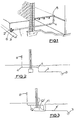
- Figure 1 is a vertical section through a house and neighbouring ground showing the usual arrangement of a gas service,
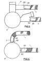
- Figure 2 is a section similar to Figure 1 but showing another, common arrangement of gas service which incorporates 90° elbows,
- Figure 3 is a section showing how the service of Figure 2 is diverted during lining of the service in accordance with the invention,
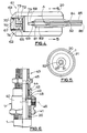
- Figure 4 is a longitudinal cross-section of one end of a plastics liner fitted with a termination assembly, the free end of the flexible means being shown unattached to the plug,
- Figure 5 is a section on the line 5-5 of Figure 4 but showing the liner in position in a service,
- Figure 6 shows schematically the service head adaptor secured in position on the free end of the existing gas service, with the liner in position and cut to length, and showing the second upper end portion of the service head adaptor secured in position in readiness for sealant injection,
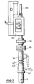
- Figure 7 shows schematically the various components assembled on the free end of the existing gas service during insertion of the liner,
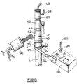
- Figure 8 shows that assembly of components which is subsequently mounted on the gas service for insertion of the sealant material, and
- Figures 9 and 10 show the final positions of the terminator for different connection configurations between the service and the main.
- Figure 1 shows the usual arrangement of
steel gas service 1 connecting at 2 with a gas main 3, theservice 1 incorporating bends, such as 4, rather than elbows. It is possible to line such a metal service by pushing through it a plastics pipe, typically of 20 mm external diameter and of thickness 2.22 mm. Other diameters, such as 16, 25, 32, 40, 63, 90 mm, can be used. Conventionally it would be necessary to dig a hole to expose theconnection 2. By the inventive process the plastics pipe is pushed through the service from themeter cock end 5, hereinafter referred to as the 'free end' of the service, until it reaches thatend 6 connected to the main, hereinafter referred to as the 'connected end' of the service. - The various stages of a lining procedure in accordance with the invention will now be set out in sequence:
- The existing meter cock 8, Figure 2, is disconnected. A gland similar to
gland 13 of Figure 7, is screwed onto the service in place of the meter cock 8. A flexible rod assembly is inserted and pushed manually through the gland, which is adapted to seal with the rod, and the rod assembly inserted until it stops upon reaching the main 3. This procedure tests whether or not a pipe can be inserted and also gives an approximate measurement of the total length of service. - Adhesive tape is attached to the rod assembly to mark this position. (If it is not possible to negotiate the service, as in the arrangement of Figure 2 where
elbows 4 are used, then ahole 11 is dug adjacent the building andpart 12 of the service is abandoned. Theremaining length 1¹, Figure 3, is lined as far as theservice 1 of Figure 1, and the new length 12¹ is laid in a conventional manner.) - The rod is then removed and a tube, not shown, of corresponding external diameter to that of the rod is inserted into the
pipe 1 through the gland unit, until the tube enters the main. The tube is progressively withdrawn from thepipe 1 whilst a low viscosity, high wicking action anaerobic liquid, such as methacrylate, is fed into the tube either as a spray or by pouring the liquid into the tube. - The anaerobic liquid can permanently seal a leaking service by coating the inside of
service 1 with a sealant. This can be particularly important at the connection between theservice 1 and the gas main 3. The coating may also be used to inhibit corrosion and thereby reduce the chances of a future leakage. This technique might also be used to provide an emergency repair of a leaking service prior to relaying of the service at a later date. - Using a meter cock exchange tool the meter cock 8 is removed. Those acquainted with the art are conversant with this process.
- A modified
service head adaptor 7, Figure 6, is then attached, as shown in Figure 8. The service head adaptor comprises alower body portion 40 adapted to be secured at itslower end 41 to the existingservice pipe 1, and at itsupper end 42 to be secured to alternative first and second service head adaptorupper end portions upper end portion 43, as shown in Figure 6, is adapted to be threadedly secured to thebody 40 and to clamp acopper sealing ring 42 against aplastics liner 20 adjacent to the cutouter extremity 45 thereof, whereas the (alternative) first upper end portion, indicated at 47 in Figure 7, is similar tosecond end portion 43, but differs fromend portion 43 in that the internal bore of the first end portion is sized to permit theliner 20 to extend therethrough. - The
body 7 is provided with aradial injection port 46. Arubber sealing ring 48, Figure 6, is secured inbody 7 by adhesive or by a star washer against ashoulder 49 aboveport 46 and is adapted to seal with the outer surface ofliner 20 when the liner is in position in thebody 7. - The service head adaptor shown in Figure 6 is a modification of the 'KONTITE' (TM) fitting manufactured by Kay & Co (Engineers) Ltd of Bolton, Lancashire.
- Figure 7 shows the assembly of components which is mounted on the
free end 5 of the existingservice 1 to enable theplastics liner 20 to be inserted into the service with a minimum release of gas. As shown, afull bore valve 14 withintegral gland unit 13 is mounted on top of the firstupper end portion 47. - A pushing
machine 15 is then attached. Meanwhile outside the property a piece ofplastics liner 20 is measured to about 1 metre longer than that length of the rod assembly 9 between the free end of the rod end unit 17 and tape marker and is cut. - The additional length of 1 metre is to provide a sufficient length of liner to be engaged by the pushing machine, even when the
liner 20 has reached the fully installed position. - Before proceeding to describe the insertion of the
liner 20, it is necessary to digress to describe the termination assembly and capacitance sensor. - With reference to Figures 4 and 5, a
termination assembly 61 comprises atubular terminator 62 having a frusto-conical 'streamline'portion 63 covering the extremity 64 of theliner 20, and anintegral spigot portion 66 adapted to be a tight fit within theliner 20. Aplug 67 is adapted to have a snap-engagement with ascrew 68 in the extremity of apolyamide tube 69 which constitutes an end portion of a flexible elongate means for withdrawing theplug 67 at the appropriate stage through the bore of theliner 20. -
Plug 67 is formed with a first externalannular recess 70 in which is seated a replaceable 0-ring seal 70¹. - The bore of
terminator 62 is slightly reduced at its free end to prevent theplug 67 from passing outwardly of theterminator 2, ie to the left of the position shown in Figure 4. - The rear half of
plug 67 is split to define a semicircular latch block 72 which is held captive to the main part ofplug 67 by a circlip 73 located in a second annular recess inplug 67. - The rear end of
plug 67 has an axial blind bore 74, and an internal lip 75 at the entrance to bore 74 provides a snap connection with a frusto-conical head 79 onscrew 68. - The capacitative sensor comprises a length of tubular wire mesh forming an
electrode 81 which is coaxially carried by thetube 69 and is encased by ashrink sleeving 82. Theelectrode 81 andsleeving 82 extend axially adjacent to thespigot portion 66, which is of an electrically conductive material. This has the effect of substantially increasing the sensitivity of the capacitative sensor, formed by theelectrode 81 in conjunction with themetal pipe 1 being lined, to the flow of sealant material (along the annular gap between thesleeve 20 and the pipe) as the sealant closely approaches the position of thespigot 66. Thesleeving 82 protects theelectrode 81 against abrasion and increases the effective tensile strength oftube 69. - The provision of
plug 67 during insertion of theliner 20 into a pipe prevents debris from entering the liner. - The
tube 69 may be filled with a flexible sealant to increase the rigidity and strength of the tube, and thetube 69 is adhesively secured within theend 84 of afurther polyamide tube 85 which constitutes a main portion of the flexible elongate means. - The inner core of a
coaxial cable 86 extends through a hole A in thetube 69 to connect with themesh 81. - Having now described the
termination assembly 61 and capacitative sensor, the description of the liner insertion procedure will now be continued. - The
terminator 62 is fitted to one end of the cut length ofliner 20, following the insertion of afirst plug 67 into theterminator 62, whereby theterminator 62 containing first plug 67 seals that end ofliner 20. Theliner 20 is then pressure tested at 100 mb for five minutes. No pressure drop is acceptable. - On operating the pushing machine, the
liner 20 is inserted to a datum position which is when theterminator 62 is arrested by the main 3 or by theconnection 2 with the main. - If the
connection 2 betweenservice 1 and the main 3 is a direct connection, as shown in Figure 10, then theliner 20 will be arrested when theterminator 62 has traversed the interior of the main 3. Alternatively, if theconnection 2 is a TEE or branch connection as shown in Figure 9, then theterminator 62 will be arrested by that connection and will not enter the main 3. The nature of theconnection 2 can be sensed by utilising thecapacitative sensor 61 to measure whether or not theterminator 62 has entered the main 3. - A second plug, which is conveniently identical to
first plug 67 shown in Figure 4, is snap-fitted to thescrew 68, andtube 69 with accompanyingcapacitative sensor 81 and second plug are inserted into the free end of theliner 20 until thetube 69 is arrested by the abutment of the second plug with thefirst plug 67. The value of the capacitor formed by thesensor mesh 81 with theservice 1 is then monitored as thetube 69 is withdrawn by about 1m. - That is, the capacitance is monitored as the second plug is retracted gradually from the
first plug 67. - The capacitance is measured by applying a fixed frequency signal to the capacitor via the
coaxial cable 86, the outer conductor of which is driven in sympathy with the inner by means of a unity gain buffer amplifier. This cancels the shunting effect of the stray cable to service pipe capacitance and so allows the current to the sensor capacitor to be monitored. - The measured value of the sensor capacitance will increase as the
tube 69 is withdrawn if theterminator 62 is located within the main 3, but if, on the other hand, theterminator 62 had not entered the main 3, the capacitance will stay substantially constant as thetube 69 is withdrawn by 1 m. - If it is ascertained by such measurements that the
terminator 62 is in the main 3, then theliner 20 is withdrawn by the exact length corresponding to the diameter of main 3, to the position shown in Figure 10. If it is ascertained that theterminator 62 has not entered the main 3, because theconnection 2 is as in Figure 9, theliner 20 is withdrawn by 50 mm to provide a sufficient clearance between theterminator 62 and theconnection 2. - The
tube 69 and second plug are then removed completely from theliner 20. Thepusher 15 andgland 13 are then detached. - The
liner 20 can then be cut to the correct length andupper portion 43 of the service head adaptor is fitted. - A
new meter cock 50 is then installed on the top ofportion 43, and the other components shown in Figure 8 are then attached, namely agas seal unit 89 which is part of the meter cock exchange kit, asealant injection gun 90, and an earthingclamp 91 with pointedscrew 92. - The
gas seal unit 89 is provided with atest nipple 93. -
Clamp 91 is connected bystrap 94 to acontrol box 95 for monitoring the capacitance of the capacitative sensor, thecoaxial lead 86 being plugged into asocket 96. - The
tube 69 without a plug attached is then inserted into theliner 20 through thegas seal unit 89 and is pushed through the liner as far as possible until thehead 79 ofscrew 68 is arrested by theplug 67 located interminator 62. It is important to ensure that thehead 79 has engaged with theplug 67 because this engagement determines the precise axial position of thecapacitance sensor 81 relative to the free end 64 ofliner 20. This engagement can be tested by withdrawing thetube 69 by 50 mm and monitoring gas flow throughnipple 93. If thehead 79 has snap-engaged with theplug 67, then the plug will be withdrawn fromterminator 62 thereby allowing some gas flow past 0-ring 70¹. Thetube 69 is then fully re-inserted to reposition theplug 67 interminator 62. - Sealant is then injected by
gun 90 into the annular space between theliner 20 andpipe 1 throughinjection port 46, and the value of the capacitance between theelectrode 81 and thepipe 1 is monitored, as before, by theunit 95. A significant change in the measured capacitance is produced when the sealant closely approaches the region of theelectrode 81, because the sealant provides a dielectric interposed between the plates of the capacitor. An indicator buzzer is activated by a capacitor monitor circuit in response to a preset threshold level being reached, and the operator ceases to operate thegun 90. Thus it is ensured that the sealant is not injected into the main 3, but stops short of theterminator 62. - The
tube 69 is then withdrawn, bringing with it theplug 67, which is withdrawn through themeter cock 50 andseal unit 89. Theliner 20 is then purged, and themeter cock 50 is turned off. - The service is now complete. A label is attached to the riser "Warning, this service has been live-inserted".
- This will inform operatives that there is only a 500 mm tail of unsealed
pipe 20 at the connected end. - Services vary in size and length and method of connection to the main. Our system has the advantage that by sensing the sealant when it has reached the correct position, all of the
annular space 31 is filled. Even if services are unsound, the sealant will automatically continue to be pumped until all the gap is filled. - As there is usually no excavation, service renewal could possibly be undertaken by personnel restricted to light duties or possibly to a one-man operation.
- During the process of service renewal, an 'air mover' (TM) device or similar coanda effect device , not shown, can be attached to the existing riser so as to remove odours and small volumes of venting gas to outside the property.
- A suitable sealant for filling the annular space is a one-part methacrylate with a formulation to form a low base viscosity yet made thixotropic by the addition of thickening agents. The sealant used is typically of a one part anaerobic thixotropic gel type and the insertion nozzle consists of a disposable combined catalyst and mixer which triggers the gel to cure it.
- A preferred sealant is ANNERSEAL (TM) supplied by Chemence Limited of Princewood Road, Corby, Northamptonshire NN17 2XD. ANNERSEAL is a mixture of methacrylates, cumene hydroperoxide initiator and metal catalyst with trace additives.
- Other sealants for the annular gap can also be used, for example polyurethanes, epoxies, acrylics, cyanoacrylates, silicones, polyesters, polysulphides, latices or cement or clay based sealants.
Claims (8)
- A method of lining a pipe (1) which has an underground connection (2) with a further pipe (3) comprising inserting a tubular liner (20) into the pipe (1) from the free end (5) opposite to the underground connection (2) such that the liner extends adjacent to or through the connection, by effecting a seal between the liner (20) and the pipe (1), or between the liner (20) and the connection (2), by injecting a flowable sealant so as to close-off the annular space defined between the liner and the pipe in the region adjacent to said connection, the sealant being introduced into the pipe (1) from the pipe end (5) remote from the connection, characterised in that a sealant detection means (81, 86, 94, 95) is provided to detect when the sealant closely reaches the connection (2), so as to enable the injection of sealant into the annular space to be terminated.
- The method of claim 1 characterised in that the sealant detection means comprises a sensor means (81) which is arranged in the liner (20) adjacent the connection (2) and produces a signal when the sealant reaches or closely approaches the sensor means.
- The method of claim 2 characterised in that the signal produced by the sensor means (81) is an electrical signal.
- The method of claim 3 characterised in that the sensor means (81) is a capacitative sensor, and the pipe (1) being lined is of metal, one electrode of the capacitative sensor being provided by the metal pipe (1) being lined, and the other electrode by an insert (81) which is arranged to be temporarily located within the liner (20) at a location spaced along the pipe (1) by a predetermined amount from the underground end thereof.
- The method according to any one of claims 2, 3 or 4, in which the sensor means (81) is carried by a flexible elongate carrier (69) which is inserted into the liner (20), and is withdrawn from the liner (20) after insertion of the sealant.
- The method according to any of the preceding claims characterised in that the liner (20) is fitted with a termination assembly comprising a tubular terminator (62) having a generally streamlined portion (63) adapted to abut with that end (64) of the liner which is inserted into the pipe (1) to be lined, and a spigot portion (66) adapted to be a firm fit within that end of the liner, the streamlined portion substantially covering the cut extremity (64) of that end of the liner, and a plug (67) which is adapted to seal the bore of the terminator and to be retractable from the terminator through the bore of the liner (20).
- The method according to claim 6 as appended directly or indirectly to claim 4, in which said capacitor electrode (81) is mounted on an elongate flexible means (69) adjacent a connector (68) adapted to connect said flexible means (69) and the plug (67).
- The method according to any one of claims 4 to 7, characterised by arranging the capacitative sensor means (81) within the liner (20) adjacent to the underground end of the liner, and retracting the sensor means (81) by a predetermined amount whilst monitoring the capacitance between the sensor means (81) and the metal pipe (1) being lined, using the monitored capacitance characteristic to determine the type of connection (2) between the pipe (1) and the further pipe (3), and then repositioning the liner (20) axially in the pipe (1) according to the detected type of connection.
Applications Claiming Priority (5)
| Application Number | Priority Date | Filing Date | Title |
|---|---|---|---|
| GB909017081A GB9017081D0 (en) | 1990-08-03 | 1990-08-03 | Inserting linings into pipes |
| GB9017081 | 1990-08-03 | ||
| GB909025990A GB9025990D0 (en) | 1990-11-29 | 1990-11-29 | Inserting linings into pipes |
| GB9025990 | 1990-11-29 | ||
| PCT/GB1991/001327 WO1992002755A1 (en) | 1990-08-03 | 1991-08-02 | Inserting linings into pipes |
Publications (2)
| Publication Number | Publication Date |
|---|---|
| EP0541623A1 EP0541623A1 (en) | 1993-05-19 |
| EP0541623B1 true EP0541623B1 (en) | 1996-03-06 |
Family
ID=26297449
Family Applications (1)
| Application Number | Title | Priority Date | Filing Date |
|---|---|---|---|
| EP91913763A Expired - Lifetime EP0541623B1 (en) | 1990-08-03 | 1991-08-02 | Inserting linings into pipes |
Country Status (4)
| Country | Link |
|---|---|
| US (1) | US5468091A (en) |
| EP (1) | EP0541623B1 (en) |
| DE (1) | DE69117760D1 (en) |
| WO (1) | WO1992002755A1 (en) |
Families Citing this family (5)
| Publication number | Priority date | Publication date | Assignee | Title |
|---|---|---|---|---|
| GB2408340A (en) * | 2003-11-18 | 2005-05-25 | Radiodetection Ltd | A vehicle for inspecting a pipe |
| US20070214994A1 (en) * | 2006-03-16 | 2007-09-20 | Pierson Construction Corporation | Pipeline traverse apparatus |
| GB0708018D0 (en) * | 2007-04-25 | 2007-06-06 | Steve Vick Internat Ltd | Closing off flow passages |
| US9784388B1 (en) | 2015-06-02 | 2017-10-10 | Interstate Power Systems, Inc. | Pipe liner for abrasive materials |
| US10458940B1 (en) * | 2015-06-25 | 2019-10-29 | Atlas Sensors, LLC | Non-destructive instrument for detecting polymer inserts within polymer pipes fitted with a locator wire |
Family Cites Families (4)
| Publication number | Priority date | Publication date | Assignee | Title |
|---|---|---|---|---|
| US3294121A (en) * | 1963-06-07 | 1966-12-27 | Southern California Gas Co | Method and apparatus for inserting a tube into a pipe |
| GB2123919B (en) * | 1982-07-16 | 1986-04-30 | Vick Limited Steve | Sealing within pipes |
| DE3804674A1 (en) * | 1988-02-15 | 1989-08-24 | Rubin Gmbh & Co Kg Dipl Ing | Capacitative level-measuring probe |
| GB8830111D0 (en) * | 1988-12-23 | 1989-02-22 | British Gas Plc | Method and system for enhancing service pipes |
-
1991
- 1991-08-02 US US07/983,550 patent/US5468091A/en not_active Expired - Fee Related
- 1991-08-02 EP EP91913763A patent/EP0541623B1/en not_active Expired - Lifetime
- 1991-08-02 DE DE69117760T patent/DE69117760D1/en not_active Expired - Lifetime
- 1991-08-02 WO PCT/GB1991/001327 patent/WO1992002755A1/en active IP Right Grant
Also Published As
| Publication number | Publication date |
|---|---|
| US5468091A (en) | 1995-11-21 |
| WO1992002755A1 (en) | 1992-02-20 |
| EP0541623A1 (en) | 1993-05-19 |
| DE69117760D1 (en) | 1996-04-11 |
Similar Documents
| Publication | Publication Date | Title |
|---|---|---|
| EP0126648B1 (en) | Apparatus for sealing joints and leaks | |
| US7707704B2 (en) | Sealing methods | |
| FI84925C (en) | OMFORDRING AV AVLOPPSROER OCH LIKNANDE. | |
| US4062376A (en) | Service connection between a main and a meter in a building and method of and equipment for installing the same | |
| CA1134680A (en) | Piping leakage detection method and apparatus | |
| CN111271122B (en) | Method for monitoring external water pressure of lining | |
| US7137308B2 (en) | Sliding pipe plug | |
| US5966789A (en) | Apparatus for assisting in the insertion of an elongate plastic pipe within an existing pipe | |
| EP0541623B1 (en) | Inserting linings into pipes | |
| US20030068143A1 (en) | Method and apparatus providing fiber optic cables through gas service pipes | |
| US6199432B1 (en) | Fluid pressure testing | |
| PL180018B1 (en) | Method of and apparatus for installing a pipe in already existing pipeline | |
| US6024515A (en) | Live service pipe insertion apparatus and method | |
| US20070258773A1 (en) | Method and system for repairing subterranean structures | |
| US5200011A (en) | Non-digging tube reverse lining engineering method of conduit | |
| US20040130332A1 (en) | Sliding pipe plug | |
| US20110304336A1 (en) | Device and Method For Locating A Conduit | |
| US20230288280A1 (en) | Rod-mounted pressure sensor | |
| JP3007516B2 (en) | Supply pipe blockage method | |
| EP3064817A1 (en) | A pipe locating system and method | |
| JP2000074261A (en) | Repair method for laid pipe line | |
| EP0555570A1 (en) | Sealing of pipes | |
| JP2001280904A (en) | Method and tool for measuring length of gas conduit | |
| GB2247062A (en) | Sealing of pipes | |
| WO2004051210A1 (en) | Sliding pipe plug |
Legal Events
| Date | Code | Title | Description |
|---|---|---|---|
| PUAI | Public reference made under article 153(3) epc to a published international application that has entered the european phase |
Free format text: ORIGINAL CODE: 0009012 |
|
| 17P | Request for examination filed |
Effective date: 19930226 |
|
| AK | Designated contracting states |
Kind code of ref document: A1 Designated state(s): AT BE CH DE DK ES FR GB GR IT LI LU NL SE |
|
| RBV | Designated contracting states (corrected) |
Designated state(s): BE DE ES FR GB IT NL |
|
| 17Q | First examination report despatched |
Effective date: 19940810 |
|
| GRAH | Despatch of communication of intention to grant a patent |
Free format text: ORIGINAL CODE: EPIDOS IGRA |
|
| GRAA | (expected) grant |
Free format text: ORIGINAL CODE: 0009210 |
|
| AK | Designated contracting states |
Kind code of ref document: B1 Designated state(s): BE DE ES FR GB IT NL |
|
| PG25 | Lapsed in a contracting state [announced via postgrant information from national office to epo] |
Ref country code: NL Free format text: LAPSE BECAUSE OF FAILURE TO SUBMIT A TRANSLATION OF THE DESCRIPTION OR TO PAY THE FEE WITHIN THE PRESCRIBED TIME-LIMIT Effective date: 19960306 Ref country code: FR Effective date: 19960306 Ref country code: BE Effective date: 19960306 Ref country code: ES Free format text: THE PATENT HAS BEEN ANNULLED BY A DECISION OF A NATIONAL AUTHORITY Effective date: 19960306 Ref country code: IT Free format text: LAPSE BECAUSE OF FAILURE TO SUBMIT A TRANSLATION OF THE DESCRIPTION OR TO PAY THE FEE WITHIN THE PRE;WARNING: LAPSES OF ITALIAN PATENTS WITH EFFECTIVE DATE BEFORE 2007 MAY HAVE OCCURRED AT ANY TIME BEFORE 2007. THE CORRECT EFFECTIVE DATE MAY BE DIFFERENT FROM THE ONE RECORDED.SCRIBED TIME-LIMIT Effective date: 19960306 |
|
| REF | Corresponds to: |
Ref document number: 69117760 Country of ref document: DE Date of ref document: 19960411 |
|
| PG25 | Lapsed in a contracting state [announced via postgrant information from national office to epo] |
Ref country code: DE Effective date: 19960608 |
|
| NLV1 | Nl: lapsed or annulled due to failure to fulfill the requirements of art. 29p and 29m of the patents act | ||
| EN | Fr: translation not filed | ||
| PG25 | Lapsed in a contracting state [announced via postgrant information from national office to epo] |
Ref country code: GB Effective date: 19960802 |
|
| PLBE | No opposition filed within time limit |
Free format text: ORIGINAL CODE: 0009261 |
|
| STAA | Information on the status of an ep patent application or granted ep patent |
Free format text: STATUS: NO OPPOSITION FILED WITHIN TIME LIMIT |
|
| 26N | No opposition filed | ||
| GBPC | Gb: european patent ceased through non-payment of renewal fee |
Effective date: 19960802 |