EP0541294B1 - Droplet ejecting device - Google Patents
Droplet ejecting device Download PDFInfo
- Publication number
- EP0541294B1 EP0541294B1 EP92309926A EP92309926A EP0541294B1 EP 0541294 B1 EP0541294 B1 EP 0541294B1 EP 92309926 A EP92309926 A EP 92309926A EP 92309926 A EP92309926 A EP 92309926A EP 0541294 B1 EP0541294 B1 EP 0541294B1
- Authority
- EP
- European Patent Office
- Prior art keywords
- ink
- block
- ejecting device
- droplet ejecting
- base block
- Prior art date
- Legal status (The legal status is an assumption and is not a legal conclusion. Google has not performed a legal analysis and makes no representation as to the accuracy of the status listed.)
- Expired - Lifetime
Links
- 239000000919 ceramic Substances 0.000 claims description 34
- 230000005684 electric field Effects 0.000 claims description 19
- 238000000034 method Methods 0.000 claims description 7
- 239000000853 adhesive Substances 0.000 claims description 6
- 230000001070 adhesive effect Effects 0.000 claims description 6
- 238000005520 cutting process Methods 0.000 claims description 6
- 238000004519 manufacturing process Methods 0.000 claims description 6
- 239000011248 coating agent Substances 0.000 claims description 4
- 238000000576 coating method Methods 0.000 claims description 4
- 238000005304 joining Methods 0.000 claims description 3
- 239000000463 material Substances 0.000 claims description 3
- 230000010287 polarization Effects 0.000 claims description 3
- 239000011347 resin Substances 0.000 claims description 2
- 229920005989 resin Polymers 0.000 claims description 2
- 239000002184 metal Substances 0.000 description 26
- 230000003247 decreasing effect Effects 0.000 description 5
- 230000000694 effects Effects 0.000 description 5
- 230000004075 alteration Effects 0.000 description 1
- 229910010293 ceramic material Inorganic materials 0.000 description 1
- 238000010586 diagram Methods 0.000 description 1
- 229910003460 diamond Inorganic materials 0.000 description 1
- 239000010432 diamond Substances 0.000 description 1
- 239000007772 electrode material Substances 0.000 description 1
- 239000011521 glass Substances 0.000 description 1
- 238000002347 injection Methods 0.000 description 1
- 239000007924 injection Substances 0.000 description 1
- 238000012986 modification Methods 0.000 description 1
- 230000004048 modification Effects 0.000 description 1
- 238000003825 pressing Methods 0.000 description 1
- 239000007779 soft material Substances 0.000 description 1
- 239000007787 solid Substances 0.000 description 1
- 238000005507 spraying Methods 0.000 description 1
Images


Classifications
-
- B—PERFORMING OPERATIONS; TRANSPORTING
- B41—PRINTING; LINING MACHINES; TYPEWRITERS; STAMPS
- B41J—TYPEWRITERS; SELECTIVE PRINTING MECHANISMS, i.e. MECHANISMS PRINTING OTHERWISE THAN FROM A FORME; CORRECTION OF TYPOGRAPHICAL ERRORS
- B41J2/00—Typewriters or selective printing mechanisms characterised by the printing or marking process for which they are designed
- B41J2/005—Typewriters or selective printing mechanisms characterised by the printing or marking process for which they are designed characterised by bringing liquid or particles selectively into contact with a printing material
- B41J2/01—Ink jet
- B41J2/135—Nozzles
- B41J2/14—Structure thereof only for on-demand ink jet heads
- B41J2/14201—Structure of print heads with piezoelectric elements
- B41J2/14209—Structure of print heads with piezoelectric elements of finger type, chamber walls consisting integrally of piezoelectric material
-
- B—PERFORMING OPERATIONS; TRANSPORTING
- B41—PRINTING; LINING MACHINES; TYPEWRITERS; STAMPS
- B41J—TYPEWRITERS; SELECTIVE PRINTING MECHANISMS, i.e. MECHANISMS PRINTING OTHERWISE THAN FROM A FORME; CORRECTION OF TYPOGRAPHICAL ERRORS
- B41J2/00—Typewriters or selective printing mechanisms characterised by the printing or marking process for which they are designed
- B41J2/005—Typewriters or selective printing mechanisms characterised by the printing or marking process for which they are designed characterised by bringing liquid or particles selectively into contact with a printing material
- B41J2/01—Ink jet
- B41J2/135—Nozzles
- B41J2/14—Structure thereof only for on-demand ink jet heads
- B41J2002/14379—Edge shooter
-
- B—PERFORMING OPERATIONS; TRANSPORTING
- B41—PRINTING; LINING MACHINES; TYPEWRITERS; STAMPS
- B41J—TYPEWRITERS; SELECTIVE PRINTING MECHANISMS, i.e. MECHANISMS PRINTING OTHERWISE THAN FROM A FORME; CORRECTION OF TYPOGRAPHICAL ERRORS
- B41J2/00—Typewriters or selective printing mechanisms characterised by the printing or marking process for which they are designed
- B41J2/005—Typewriters or selective printing mechanisms characterised by the printing or marking process for which they are designed characterised by bringing liquid or particles selectively into contact with a printing material
- B41J2/01—Ink jet
- B41J2/135—Nozzles
- B41J2/14—Structure thereof only for on-demand ink jet heads
- B41J2002/14387—Front shooter
Definitions
- the invention relates to a droplet ejecting device, such as a droplet ejecting device which uses deformation of a piezoelectric transducer.
- a piezoelectric ink jet type printer head has been conventionally proposed, wherein the volume of an ink passage is changed using the deformation of a piezoelectric transducer. Ink staying in the ink passage is ejected through an orifice at the time of a decrease in volume while ink is introduced into the ink passage, via a valve disposed on a side opposite to the orifice, at the time of an increase in volume.
- This type of ink jet printer head is called a drop-on-demand type.
- a plurality of ejectors, each structured as described are arranged adjacent to one another. The ink is ejected from the ejector(s) located in a predetermined position(s) so that a desired character or image is formed.
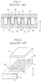
- Figs. 4 and 5 schematically show one of conventional droplet injecting devices.
- This conventional device will be explained in detail hereinafter referring to Fig. 4, which is a cross sectional view showing a part of an array of the conventional droplet ejecting device.
- a piezoelectric ceramic plate (piezoelectric transducer) 1 which has a plurality of side walls 2A, 2B, 2C and 2D and is polarized in the direction indicated by an arrow 51, is bonded to a cover plate 21 made of a metal, glass or ceramic material via a bonding layer 12.
- the walls 2A, 2B, 2C, 2D and the outside walls define ink passages 31A, 31B and 31C.
- Each ink passage 31 is formed into an elongated shape of a rectangular cross section.
- the side walls 2 extend along the entire length of the ink passage, and can be deformed in the vertical direction with respect to an axis of the ink passage and the polarizing direction.
- a metal electrode 11 for applying a driving electric field is formed on the side wall 2.
- the ink passage 31B is selected on the basis of a predetermined print data, a driving electric field is applied between the metal electrodes 11C and 11D, and between the metal electrodes 11E and 11F, respectively. Since the direction of the driving electric field is perpendicular to the polarizing direction, the side walls 2B and 2C are deformed inward of the ink passage 31B by a piezoelectric thickness shear effect. With this deformation, the volume of the ink passage 31B is decreased so that the ink pressure is increased. Accordingly, an ink droplet is ejected through an orifice 42 (see Fig. 5). When application of the drive electric field is stopped, the side walls return to their original positions, before the deformation, so that the ink pressure in the passage is decreased. Consequently, ink is supplied into the passage from an ink supplying portion (not shown).
- the array is manufactured by the following method. As shown in Fig. 5, parallel grooves 3, constituting the ink passages having the above-mentioned shape, are formed in the piezoelectric ceramic plate 1, polarized in the direction indicated by the arrow 51, by grinding using a diamond cutting disk. On the sides of the groove 3, the aforementioned metal electrode is formed by spattering or the like.
- the cover plate 21 is bonded to the upper grooved surface 4A of the piezoelectric ceramic plate 1.
- An orifice plate 41 is bonded to the end surface 4B, on the ink ejecting side of the piezoelectric ceramic plate 1.
- the orifice plate 41 is provided with orifices 42 formed to correspond to the face of the ink passages.
- the side walls of the piezoelectric ceramics are deformed inward of the ink passages by the piezoelectric thickness shear effect.
- the side walls of the piezoelectric ceramics are interposed between the adjacent ink passages, it is impossible to simultaneously eject ink droplets from the adjacent ink passages. Consequently, the array of the droplet ejecting device is divided into a plurality of groups for ejection control. Therefore, an ink ejecting cycle of the array as a whole in the droplet ejecting device is longer, than that in the case where the ink droplets can be simultaneously ejected from the adjacent ink passages, with an attendant problem of a low print speed.
- the metal electrode is disposed on the side walls, i.e., only on the inner surfaces of the groove.
- the metal electrode is disposed on the side walls and on the upper surface of the side wall by spattering or the like, and then, the metal electrode material disposed in the upper surface of the side wall must be removed. As a result, manufacturing of the metal electrode is complicated and difficult.
- An aim of the applicant is to provide a droplet ejecting device where an ink ejecting cycle of the array as a whole in the droplet ejecting device is short, a print speed is high, and the electrode can be easily manufactured.
- US-A-4,825,227 on which the precharacterising portion of appended claim 1 is based, discloses a piezoelectric transducer ink jet system in which the rear walls of an array of ink chambers facing their respective ejecting orifices are formed from a common piezoelectric plate.
- the direction of polarization of the plate alternates along its length such that each rear wall of a chamber is polarized in opposite directions and may be sheared by providing electric fields through the thickness of the plate.
- US-A-4,383,264 discloses an ink ejecting device comprising a plate defining both a plurality of orifices and chambers behind each orifice. Ink is ejected from each orifice by the action of respective piston members or a flexible sheet driven by respective piezoelectric transducers towards and away from the chambers.
- the transducers are of the bimorph type. This means the transducers comprise two planar pieces of piezoelectric material, both having a polarisation direction perpendicular to their major plane and being joined together by major surfaces such that the polarisation direction of one piece is in the opposite direction to the polarisation direction of the other direction.
- a droplet ejecting device having a plurality of ejectors in which a volume of an ink chamber of each ejector is changeable by the use of a piezoelectric transducer to eject ink from the ink chamber, said droplet ejecting device comprising:
- the injection control means applies an electric field to the electrodes located in the predetermined position so that the first and second piezoelectric transducers polarised in the directions opposite to each other are deformed by the piezoelectric thickness shear effect with application of the electric field. Consequently, the ink pressure in the ink chamber is increased and the ink droplet can be ejected from the ink chamber through the orifice.
- a droplet ejecting device comprising the steps of:
- FIG. 1 A first piezoelectric ceramic block (piezoelectric transducer) 6 is polarised in the direction indicated by an arrow 56. Additionally, a second piezoelectric ceramic block (piezoelectric transducer) 7 is polarized in the direction indicated by an arrow 57. The first piezoelectric block 6 and the second piezoelectric block 7 are bonded to each other via a bonding layer 16.
- a groove 17 constituting a part of the ink chambers is defined by an inner surface of the first and second piezoelectric blocks 6, 7, while slits 18 for dividing the piezoelectric blocks 6, 7 into the ink chambers are formed at the outer surface of each of the piezoelectric blocks 6,7.
- a metal electrode 26, for applying a driving electric field is formed over the outer surface, that is the slit 18 side except for in the slits 18; and another metal electrode 27, for applying a driving electric field, is formed over the inner surface, that is the groove 17 side, of the piezoelectric blocks 6,7 by spattering or the like.
- the slits 18 are formed after assembly of the piezoelectric blocks 6,7 and the application of electrodes 26, 27.
- a member 36 for completing the ink chambers is made of a soft material such as a resin material and is provided at one surface thereof with side walls 37 facing to the slits 18.
- An orifice 38 is formed, in a middle position between the adjacent side walls 37, facing to the ink chamber.
- the array consisting of the first and second piezoelectric ceramic blocks 6, 7 is fitted to the member 36 to define the ink chambers with the side walls 37 and the orifices 38 centered in the ink chambers.
- This fitting is carried out by bonding with an adhesive, by pressing together in a tight fit or a similar manner such that the assembled piezoelectric blocks 6,7 and the member 36 define a plurality of ink chambers.
- An ink supply chamber 43 is mounted to an upper surface of the array consisting of the first and second piezoelectric ceramic blocks 6,7 and member 36.
- Inlet 44 and outlet 45 are connected to an ink reservoir (not shown). Ink supplied from the ink reservoir enters ink supplying path 5, via inlet 44 found in ink supplying chamber 43, and is then fed downwardly through openings 47, formed in an upper front portion of piezoelectric block 7, into the ink chambers.
- Outlet 45 is provided to permit circulation of the ink. Openings 47 are midway between sidewalls 37 defining each ink chamber.
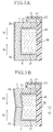
- Figs. 3A and 3B are cross sectional views showing one of ejectors in the array of the droplet ejecting device.
- a driving electric field is applied, by an ejection control system 28 in a known manner, between the metal electrodes 26,27 of the first and second piezoelectric blocks 6,7. Since the direction of the driving electric field is perpendicular to the polarizing direction, the first and second piezoelectric blocks 6,7 are deformed inward into the groove 17 constituting a part of the ink chamber by a piezoelectric thickness shear effect.
- the side walls of the piezoelectric ceramics which are deformed by the application of a driving voltage, are positioned between the ink passages so that it is impossible to simultaneously eject the ink droplets from adjacent ink passages. Consequently, the array of the droplet ejecting device is divided into a plurality of groups for ejection control. Therefore, the ink ejecting cycle of the array as a whole in the droplet ejecting device is longer than that in the case where the ink droplets can be simultaneously ejected from the adjacent ink passages with an attendant problem of a low print speed.
- the piezoelectric ceramic blocks 6,7 which are deformed by the application of the driving voltage are not interposed between adjacent ink chambers but are disposed in the lateral direction, that is, they form an end wall of the adjacent ink chambers and, accordingly, the ink droplets can be simultaneously ejected from adjacent ink passages. Therefore, the ink ejecting cycle of the array as a whole in the droplet ejecting device is short resulting in a high print speed.
- the metal electrode is disposed on the surface of each side wall, i.e., only at the side surfaces of the grooves.
- the conventional device is therefore accompanied by the problems that when the metal electrodes are formed on the surface they are also formed on the upper surface of the side wall by the spattering or other method and the metal electrode formed at the upper surface of the side wall must be removed. As a result, the manufacturing process of the metal electrode is complicated and difficult.
- the first and second piezoelectric ceramic blocks 6,7 are bonded, such as by an adhesive, to each other and the groove 17 constituting a part of the ink chamber is formed before the metal electrode 27 is disposed over the whole inner surface of the groove 17 and the metal electrode 26 is disposed over the rear outer surface by spattering or the like. Then, the metal electrodes 26 can be separated by simply forming the slits 18. As a result, the metal electrode 26 is divided into parts for each of the droplet ejectors and the metal electrode 27 is common for all of the droplet ejectors. Therefore, the manufacture of the metal electrode is remarkably facilitated.
- the first and second piezoelectric ceramic blocks are formed to have an L-shaped cross section.
- the two piezoelectric ceramic blocks 6,7 are then bonded at the ends of their base legs by means of an adhesive to form a base block having a U-shaped cross section.
- solid blocks may be bonded together and then a grove 17 cut therein centered on the bond.
- the L-shaped piezoelectric ceramic blocks 6,7 bonded at one end are formed and produce the U-shaped base block.
- the inner surface of the base block, which defines a groove 17, is coated with the metal electrode 27 by spraying, spattering or other known application methods and the metal electrode 26 is coated on the base outer surface in a similar manner.
- Slits 18 are then cut into the base part of the base block to divide the metal electrode 26 into separate electrodes for each of the ink droplet ejectors.
- openings 47 are cut into the end of piezoelectric ceramic block 7 opposite that end bonded to piezoelectric ceramic block 6. (Alternatively, openings 47 could be found in piezoelectric ceramic block 7 when it is formed.)
- Member 36 is then bonded to the base block using an adhesive or, alternatively, by tight fitting within the groove 17 of the base block in order to define the plurality of ink chambers.
- ink supplying chamber 43 is bonded to the base block and an edge of the member 36 so as to overlay and be connected with openings 47.
- first and second piezoelectric ceramic blocks 6,7 may be reversely polarized to the directions indicated by the arrows 56 and 57.
- the applying direction of the electric field in ejecting the ink droplet and supplying the ink may be the reverse to the aforementioned direction.
- the first and second piezoelectric ceramic blocks may be deformed by the application of the driving voltage outward of the groove 17 constituting a part of the ink chamber by the piezoelectric thickness shear effect. This deformation allows a volume of the groove 17 to be increased while the pressure of the ink inside the ink chamber is decreased thus supplying the ink from the ink supplying passage 5 through opening 47.
- the rear wall upon stopping the application of the driving electric field, the rear wall returns to the original position before the deformation so that the ink pressure inside the groove 17 is increased and the ink droplet 46 is ejected through the orifice 38.
- the piezoelectric transducers which are deformed by the application of the driving voltage are not interposed between the adjacent ink chambers but disposed in the lateral direction of the adjacent ink chambers. Consequently, the ink droplets can be simultaneously ejected from adjacent ink passages and the ink ejecting cycle of the array as a whole is short so that a print speed becomes high. Additionally, the metal electrodes can be easily formed.
Landscapes
- Particle Formation And Scattering Control In Inkjet Printers (AREA)
Description
- The invention relates to a droplet ejecting device, such as a droplet ejecting device which uses deformation of a piezoelectric transducer.
- A piezoelectric ink jet type printer head has been conventionally proposed, wherein the volume of an ink passage is changed using the deformation of a piezoelectric transducer. Ink staying in the ink passage is ejected through an orifice at the time of a decrease in volume while ink is introduced into the ink passage, via a valve disposed on a side opposite to the orifice, at the time of an increase in volume. This type of ink jet printer head is called a drop-on-demand type. A plurality of ejectors, each structured as described are arranged adjacent to one another. The ink is ejected from the ejector(s) located in a predetermined position(s) so that a desired character or image is formed.
- This type of droplet ejecting device is disclosed in, for example, U.S. Patents Nos. 4,992,808; 5,003,679; 5,028,936. Figs. 4 and 5 schematically show one of conventional droplet injecting devices. This conventional device will be explained in detail hereinafter referring to Fig. 4, which is a cross sectional view showing a part of an array of the conventional droplet ejecting device. A piezoelectric ceramic plate (piezoelectric transducer) 1, which has a plurality of
side walls arrow 51, is bonded to acover plate 21 made of a metal, glass or ceramic material via abonding layer 12. Thewalls ink passages - In the array, if the
ink passage 31B is selected on the basis of a predetermined print data, a driving electric field is applied between themetal electrodes metal electrodes side walls ink passage 31B by a piezoelectric thickness shear effect. With this deformation, the volume of theink passage 31B is decreased so that the ink pressure is increased. Accordingly, an ink droplet is ejected through an orifice 42 (see Fig. 5). When application of the drive electric field is stopped, the side walls return to their original positions, before the deformation, so that the ink pressure in the passage is decreased. Consequently, ink is supplied into the passage from an ink supplying portion (not shown). - The array is manufactured by the following method. As shown in Fig. 5,
parallel grooves 3, constituting the ink passages having the above-mentioned shape, are formed in the piezoelectricceramic plate 1, polarized in the direction indicated by thearrow 51, by grinding using a diamond cutting disk. On the sides of thegroove 3, the aforementioned metal electrode is formed by spattering or the like. Thecover plate 21 is bonded to the upper groovedsurface 4A of the piezoelectricceramic plate 1. Anorifice plate 41 is bonded to theend surface 4B, on the ink ejecting side of the piezoelectricceramic plate 1. Theorifice plate 41 is provided withorifices 42 formed to correspond to the face of the ink passages. - In the above described conventional droplet ejecting device, the side walls of the piezoelectric ceramics are deformed inward of the ink passages by the piezoelectric thickness shear effect.
- However, because the side walls of the piezoelectric ceramics are interposed between the adjacent ink passages, it is impossible to simultaneously eject ink droplets from the adjacent ink passages. Consequently, the array of the droplet ejecting device is divided into a plurality of groups for ejection control. Therefore, an ink ejecting cycle of the array as a whole in the droplet ejecting device is longer, than that in the case where the ink droplets can be simultaneously ejected from the adjacent ink passages, with an attendant problem of a low print speed.
- Furthermore, in the conventional droplet ejecting device described above, the metal electrode is disposed on the side walls, i.e., only on the inner surfaces of the groove. The metal electrode is disposed on the side walls and on the upper surface of the side wall by spattering or the like, and then, the metal electrode material disposed in the upper surface of the side wall must be removed. As a result, manufacturing of the metal electrode is complicated and difficult.
- An aim of the applicant is to provide a droplet ejecting device where an ink ejecting cycle of the array as a whole in the droplet ejecting device is short, a print speed is high, and the electrode can be easily manufactured.
- US-A-4,825,227, on which the precharacterising portion of appended
claim 1 is based, discloses a piezoelectric transducer ink jet system in which the rear walls of an array of ink chambers facing their respective ejecting orifices are formed from a common piezoelectric plate. The direction of polarization of the plate alternates along its length such that each rear wall of a chamber is polarized in opposite directions and may be sheared by providing electric fields through the thickness of the plate. - US-A-4,383,264 discloses an ink ejecting device comprising a plate defining both a plurality of orifices and chambers behind each orifice. Ink is ejected from each orifice by the action of respective piston members or a flexible sheet driven by respective piezoelectric transducers towards and away from the chambers. The transducers are of the bimorph type. This means the transducers comprise two planar pieces of piezoelectric material, both having a polarisation direction perpendicular to their major plane and being joined together by major surfaces such that the polarisation direction of one piece is in the opposite direction to the polarisation direction of the other direction. Application of an electric field perpendicular to the polarisation direction causes a transducer to flex, because one piece expands in the major plane and the other contracts. In the device of the citation the bi-layers are arranged across the orifices so that such flexing drives a piston member or a flexible sheet to expel ink.
- According to one aspect of the present invention there is provided a droplet ejecting device having a plurality of ejectors in which a volume of an ink chamber of each ejector is changeable by the use of a piezoelectric transducer to eject ink from the ink chamber, said droplet ejecting device comprising:
- a piezoelectric transducer having electrodes disposed on opposing inner and outer surfaces thereof and being polarized in opposite directions perpendicular to the direction of the electric field produced between said electrodes when a potential difference is applied therebetween;
- a member fitted to said inner surface of said piezoelectric transducer to define the ink chambers and having orifices in said member communicating with respective ink chambers; and
- ejection control means for applying a potential difference between the electrodes associated with a particular ink chamber so as to eject an ink droplet from the ink chamber through its associated orifice;
characterised in that - said piezoelectric transducer comprises first and second piezoelectric transducer portions which are respectively polarised in one of said opposite directions and which are bonded together, with said directions of polarization substantially perpendicular to the bond and with the bond adjacent each of said ink chambers.
- In the droplet ejecting device having the above structure the injection control means applies an electric field to the electrodes located in the predetermined position so that the first and second piezoelectric transducers polarised in the directions opposite to each other are deformed by the piezoelectric thickness shear effect with application of the electric field. Consequently, the ink pressure in the ink chamber is increased and the ink droplet can be ejected from the ink chamber through the orifice.
- According to another aspect of the present invention, there is provided a method of manufacturing a droplet ejecting device, the method comprising the steps of:
- forming two ceramic block elements each having a polarisation direction;
- joining said two ceramic block elements with said polarisation directions of said block elements in opposite directions substantially perpendicular to the join and forming a base block having a generally U-shaped cross-section;
- coating the inner surface of the U-shape of said base block with a first electrode and coating the outer surface of said base block at the base of the U-shape with a second electrode, whereby an electric field applied across the two electrodes will be perpendicular to said polarisation directions of both elements;
- cutting slits in said base block so as to divide said second electrode into a plurality of electrodes spaced along the base block;
- cutting a plurality of openings into one of said ceramic block elements at the top of the U-shape;
- attaching a member to said generally U-shaped block to fit into the U-shape to define a plurality of ink chambers within the U-shape of the block; and
- attaching an ink supply chamber communicating with said plurality of openings to the outer surface of said one of said ceramic block elements.
- To provide a better understanding of the present invention, the following non-limitative, detailed description is given, with reference to the accompanying drawings, in which:-
- Fig. 1 is a oblique view of the array of a droplet ejecting device in a preferred embodiment of the invention;
- Fig. 2 is a perspective view showing the structure of the array of the droplet ejecting device in the preferred embodiment according to the invention;
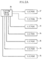
- Fig. 2A is a block diagram of the ejection control system;
- Figs. 3A and 3B are cross sectional views showing one of the ejectors in the array of the droplet injecting device, in the preferred embodiment according to the invention, with Fig. 3A showing the ejector in its normal state and Fig. 3B showing the ejector during ejection;
- Fig. 4 is a cross sectional view showing a part of an array of a conventional droplet ejecting device;
- Fig. 5 is a perspective view showing the structure of the array of the conventional droplet ejecting device.
- A droplet ejecting device embodying the invention will be described hereinafter with reference to the accompanying drawings.
- The structure will be described with reference to Figs. 1 and 2 with Fig. 2 being a perspective view of an array of the droplet ejecting apparatus of the preferred embodiment according to the invention. A first piezoelectric ceramic block (piezoelectric transducer) 6 is polarised in the direction indicated by an
arrow 56. Additionally, a second piezoelectric ceramic block (piezoelectric transducer) 7 is polarized in the direction indicated by anarrow 57. The firstpiezoelectric block 6 and the secondpiezoelectric block 7 are bonded to each other via abonding layer 16. Agroove 17 constituting a part of the ink chambers is defined by an inner surface of the first and secondpiezoelectric blocks slits 18 for dividing the piezoelectric blocks 6, 7 into the ink chambers are formed at the outer surface of each of thepiezoelectric blocks metal electrode 26, for applying a driving electric field, is formed over the outer surface, that is theslit 18 side except for in theslits 18; and anothermetal electrode 27, for applying a driving electric field, is formed over the inner surface, that is thegroove 17 side, of thepiezoelectric blocks slits 18 are formed after assembly of thepiezoelectric blocks electrodes - A
member 36 for completing the ink chambers is made of a soft material such as a resin material and is provided at one surface thereof withside walls 37 facing to theslits 18. Anorifice 38 is formed, in a middle position between theadjacent side walls 37, facing to the ink chamber. - The array consisting of the first and second piezoelectric
ceramic blocks member 36 to define the ink chambers with theside walls 37 and theorifices 38 centered in the ink chambers. This fitting is carried out by bonding with an adhesive, by pressing together in a tight fit or a similar manner such that the assembledpiezoelectric blocks member 36 define a plurality of ink chambers. - An
ink supply chamber 43 is mounted to an upper surface of the array consisting of the first and second piezoelectricceramic blocks member 36.Inlet 44 andoutlet 45 are connected to an ink reservoir (not shown). Ink supplied from the ink reservoir entersink supplying path 5, viainlet 44 found inink supplying chamber 43, and is then fed downwardly throughopenings 47, formed in an upper front portion ofpiezoelectric block 7, into the ink chambers.Outlet 45 is provided to permit circulation of the ink.Openings 47 are midway betweensidewalls 37 defining each ink chamber. - Operation of the droplet ejecting device in the preferred embodiment will be described with reference to Figs. 3A and 3B, which are cross sectional views showing one of ejectors in the array of the droplet ejecting device. When one ejector is selected on the basis of a predetermined print data, a driving electric field is applied, by an
ejection control system 28 in a known manner, between themetal electrodes piezoelectric blocks piezoelectric blocks groove 17 constituting a part of the ink chamber by a piezoelectric thickness shear effect. This deformation causes the volume of thegroove 17 to be decreased while the pressure of ink inside the ink chamber is increased. As a result, an ink droplet 46 is ejected through theorifice 38. Upon stopping the application of the driving electric field, the first and second piezoelectricceramic blocks groove 17 is decreased. As a result, ink is supplied from anink supplying passage 5 through anopening 47. - In the conventional droplet ejecting device, the side walls of the piezoelectric ceramics, which are deformed by the application of a driving voltage, are positioned between the ink passages so that it is impossible to simultaneously eject the ink droplets from adjacent ink passages. Consequently, the array of the droplet ejecting device is divided into a plurality of groups for ejection control. Therefore, the ink ejecting cycle of the array as a whole in the droplet ejecting device is longer than that in the case where the ink droplets can be simultaneously ejected from the adjacent ink passages with an attendant problem of a low print speed.
- However, in the droplet ejecting device of this embodiment, the piezoelectric
ceramic blocks - Furthermore, in the conventional droplet ejecting device, the metal electrode is disposed on the surface of each side wall, i.e., only at the side surfaces of the grooves. The conventional device is therefore accompanied by the problems that when the metal electrodes are formed on the surface they are also formed on the upper surface of the side wall by the spattering or other method and the metal electrode formed at the upper surface of the side wall must be removed. As a result, the manufacturing process of the metal electrode is complicated and difficult.
- However, in the droplet injecting device of this embodiment the first and second piezoelectric
ceramic blocks groove 17 constituting a part of the ink chamber is formed before themetal electrode 27 is disposed over the whole inner surface of thegroove 17 and themetal electrode 26 is disposed over the rear outer surface by spattering or the like. Then, themetal electrodes 26 can be separated by simply forming theslits 18. As a result, themetal electrode 26 is divided into parts for each of the droplet ejectors and themetal electrode 27 is common for all of the droplet ejectors. Therefore, the manufacture of the metal electrode is remarkably facilitated. - To manufacture the droplet injecting device, the first and second piezoelectric ceramic blocks are formed to have an L-shaped cross section. The two piezoelectric
ceramic blocks grove 17 cut therein centered on the bond. As a result, the L-shaped piezoelectricceramic blocks groove 17, is coated with themetal electrode 27 by spraying, spattering or other known application methods and themetal electrode 26 is coated on the base outer surface in a similar manner.Slits 18 are then cut into the base part of the base block to divide themetal electrode 26 into separate electrodes for each of the ink droplet ejectors. In addition,openings 47 are cut into the end of piezoelectricceramic block 7 opposite that end bonded to piezoelectricceramic block 6. (Alternatively,openings 47 could be found in piezoelectricceramic block 7 when it is formed.)Member 36 is then bonded to the base block using an adhesive or, alternatively, by tight fitting within thegroove 17 of the base block in order to define the plurality of ink chambers. Lastly,ink supplying chamber 43 is bonded to the base block and an edge of themember 36 so as to overlay and be connected withopenings 47. - It is to be understood that the invention is not restricted to the embodiment described above. Various modifications and alterations can be added thereto without departing from the scope of the invention. For example, the first and second piezoelectric
ceramic blocks arrows - In addition, the applying direction of the electric field in ejecting the ink droplet and supplying the ink may be the reverse to the aforementioned direction. Namely, the first and second piezoelectric ceramic blocks may be deformed by the application of the driving voltage outward of the
groove 17 constituting a part of the ink chamber by the piezoelectric thickness shear effect. This deformation allows a volume of thegroove 17 to be increased while the pressure of the ink inside the ink chamber is decreased thus supplying the ink from theink supplying passage 5 throughopening 47. Further, upon stopping the application of the driving electric field, the rear wall returns to the original position before the deformation so that the ink pressure inside thegroove 17 is increased and the ink droplet 46 is ejected through theorifice 38. - In the droplet ejecting device according to the invention, as is apparent from the above description, the piezoelectric transducers which are deformed by the application of the driving voltage are not interposed between the adjacent ink chambers but disposed in the lateral direction of the adjacent ink chambers. Consequently, the ink droplets can be simultaneously ejected from adjacent ink passages and the ink ejecting cycle of the array as a whole is short so that a print speed becomes high. Additionally, the metal electrodes can be easily formed.
Claims (13)
- A droplet ejecting device having a plurality of ejectors in which a volume of an ink chamber of each ejector is changeable by the use of a piezoelectric transducer to eject ink from the ink chamber, said droplet ejecting device comprising:a piezoelectric transducer (6,7) having electrodes (26,27) disposed on opposing inner and outer surfaces thereof and being polarized in opposite directions perpendicular to the direction of the electric field produced between said electrodes (26,27) when a potential difference is applied therebetween;a member (36) fitted to said inner surface of said piezoelectric transducer to define the ink chambers and having orifices (38) in said member (36) communicating with respective ink chambers; andejection control means (28) for applying a potential difference between the electrodes (26,27) associated with a particular ink chamber so as to eject an ink droplet from the ink chamber through its associated orifice (38);
characterised in thatsaid piezoelectric transducer comprises first and second piezoelectric transducer portions (6,7) which are respectively polarised in one of said opposite directions and which are bonded together, with said directions of polarization substantially perpendicular to the bond and with the bond adjacent each of said ink chambers. - A droplet ejecting device as claimed in claim 1, wherein the first and second piezoelectric transducer portions (6,7) are positioned on an opposite side of the ink chambers to said member (36).
- A droplet ejecting device according to claim 1 and being for an ink jet printer, the device comprising a first block (6) and a second block (7), the first and second blocks (6,7) each having a generally L-shaped cross-section and being joined at ends of base legs of their generally L-shaped cross-sections to produce a base block having a generally U-shaped cross-section, said first and second blocks (6,7) forming, respectively, said first and second piezoelectric transducer portions of said ejectors, said electrodes being a first electrode (27) formed on an inner surface of said base block and a plurality of second electrodes (26) formed on an outer surface of said base block, the device further comprising ink supplying means (43) for supplying ink to each of said plurality of ink chambers.
- A droplet ejecting device according to claim 3, wherein said first and second blocks (6,7) are joined by an adhesive.
- A droplet ejecting device according to claim 3 or claim 4, wherein said first and second blocks (6,7) are ceramic blocks.
- A droplet ejecting device according to any one of claims 3 to 5, wherein said member (36) is bonded to said base block with an adhesive and/or press fitted together with said base block in a tight fit.
- A droplet ejecting device according to any one of claims 3 to 6, wherein said member (36) comprises:a front plate; anda plurality of panels (37) extending from a rear surface of said front plate, said panels (37) engaging said base block to form said ink chambers.
- A droplet ejecting device according to claim 7, wherein said second block (7) is provided with a plurality of openings (47), said openings (47) being situated adjacent where an end of said second block (7) joins said front plate, each opening (47) connecting said ink supply means (43) to one of said plurality of ink chambers.
- A droplet ejecting device according to claim 7 or 8, wherein a plurality of slits (18) are formed in said base block, said slits (18) opposing said panels (37) extending from said front plate and separating said plurality of second electrodes (26) formed on said outer surface of said base block.
- A droplet ejecting device according to any one of the preceding claims, wherein said member (36) is made of a resin material.
- A method of manufacturing a droplet ejecting device, the method comprising the steps of:forming two ceramic block elements (6,7) each having a polarisation direction;joining said two ceramic block elements (6,7) with said polarisation directions of said block elements in opposite directions substantially perpendicular to the join and forming a base block having a generally U-shaped cross-section;coating the inner surface of the U-shape of said base block with a first electrode (27) and coating the outer surface of said base block at the base of the U-shape with a second electrode (26), whereby an electric field applied across the two electrodes will be perpendicular to said polarisation directions of both elements;cutting slits (18) in said base block so as to divide said second electrode (26) into a plurality of electrodes spaced along the base block;cutting a plurality of openings (47) into one of said ceramic block elements (7) at the top of the U-shape;attaching a member (36) to said generally U-shaped block to fit into the U-shape to define a plurality of ink chambers within the U-shape of the block; andattaching an ink supply chamber (43) communicating with said plurality of openings (47) to the outer surface of said one of said ceramic block elements (7).
- A method according to claim 11, wherein said step of forming said base block comprises cutting, in the joined ceramic blocks (6,7) a groove (17) centred on and along a plane of the joint to produce the generally U-shaped cross-section of the base block.
- A method according to claim 11, wherein each of said two ceramic block elements (6,7) has a generally L-shaped cross-section and said step of forming said base block comprises joining the L-shape ceramic block elements (6,7) together.
Applications Claiming Priority (2)
| Application Number | Priority Date | Filing Date | Title |
|---|---|---|---|
| JP289924/91 | 1991-11-06 | ||
| JP3289924A JPH05124186A (en) | 1991-11-06 | 1991-11-06 | Liquid drop spouting device |
Publications (3)
| Publication Number | Publication Date |
|---|---|
| EP0541294A2 EP0541294A2 (en) | 1993-05-12 |
| EP0541294A3 EP0541294A3 (en) | 1993-08-25 |
| EP0541294B1 true EP0541294B1 (en) | 1997-02-12 |
Family
ID=17749527
Family Applications (1)
| Application Number | Title | Priority Date | Filing Date |
|---|---|---|---|
| EP92309926A Expired - Lifetime EP0541294B1 (en) | 1991-11-06 | 1992-10-29 | Droplet ejecting device |
Country Status (4)
| Country | Link |
|---|---|
| US (1) | US5434608A (en) |
| EP (1) | EP0541294B1 (en) |
| JP (1) | JPH05124186A (en) |
| DE (1) | DE69217449T2 (en) |
Families Citing this family (1)
| Publication number | Priority date | Publication date | Assignee | Title |
|---|---|---|---|---|
| JPH08192513A (en) * | 1995-01-18 | 1996-07-30 | Fujitsu Ltd | Piezoelectric type ink jet printer |
Citations (6)
| Publication number | Priority date | Publication date | Assignee | Title |
|---|---|---|---|---|
| US4752788A (en) * | 1985-09-06 | 1988-06-21 | Fuji Electric Co., Ltd. | Ink jet recording head |
| EP0364136A2 (en) * | 1988-10-13 | 1990-04-18 | Xaar Limited | High density multi-channel array, electrically pulsed droplet deposition apparatus |
| EP0402172A1 (en) * | 1989-06-09 | 1990-12-12 | Sharp Kabushiki Kaisha | Head for ink-jet printer |
| EP0416540A2 (en) * | 1989-09-05 | 1991-03-13 | Seiko Epson Corporation | Ink jet printer recording head |
| US5028936A (en) * | 1987-01-10 | 1991-07-02 | Xaar Ltd. | Pulsed droplet deposition apparatus using unpoled crystalline shear mode actuator |
| EP0505188A2 (en) * | 1991-03-19 | 1992-09-23 | Brother Kogyo Kabushiki Kaisha | Piezoelectric ink droplet ejecting device |
Family Cites Families (15)
| Publication number | Priority date | Publication date | Assignee | Title |
|---|---|---|---|---|
| US4032929A (en) * | 1975-10-28 | 1977-06-28 | Xerox Corporation | High density linear array ink jet assembly |
| JPS5625464A (en) * | 1979-08-09 | 1981-03-11 | Canon Inc | Liquid-drip jet recording device |
| US4383264A (en) * | 1980-06-18 | 1983-05-10 | Exxon Research And Engineering Co. | Demand drop forming device with interacting transducer and orifice combination |
| JPS57195667A (en) * | 1981-05-27 | 1982-12-01 | Ricoh Co Ltd | Ink jet printer |
| US4520374A (en) * | 1981-10-07 | 1985-05-28 | Epson Corporation | Ink jet printing apparatus |
| US4450375A (en) * | 1982-11-12 | 1984-05-22 | Kiwi Coders Corporation | Piezoelectric fluid control device |
| US5003679A (en) * | 1987-01-10 | 1991-04-02 | Xaar Limited | Method of manufacturing a droplet deposition apparatus |
| US4992808A (en) * | 1987-01-10 | 1991-02-12 | Xaar Limited | Multi-channel array, pulsed droplet deposition apparatus |
| GB8722085D0 (en) * | 1987-09-19 | 1987-10-28 | Cambridge Consultants | Ink jet nozzle manufacture |
| US4825227A (en) * | 1988-02-29 | 1989-04-25 | Spectra, Inc. | Shear mode transducer for ink jet systems |
| GB8810241D0 (en) * | 1988-04-29 | 1988-06-02 | Am Int | Drop-on-demand printhead |
| JPH023311A (en) * | 1988-06-20 | 1990-01-08 | Nec Corp | Ink jet head and manufacture thereof |
| GB8830399D0 (en) * | 1988-12-30 | 1989-03-01 | Am Int | Method of testing components of pulsed droplet deposition apparatus |
| JP2867437B2 (en) * | 1989-07-19 | 1999-03-08 | ブラザー工業株式会社 | Piezoelectric inkjet printer head |
| JP3139511B2 (en) * | 1990-11-09 | 2001-03-05 | セイコーエプソン株式会社 | Inkjet recording head |
-
1991
- 1991-11-06 JP JP3289924A patent/JPH05124186A/en active Pending
-
1992
- 1992-09-21 US US07/947,395 patent/US5434608A/en not_active Expired - Lifetime
- 1992-10-29 DE DE69217449T patent/DE69217449T2/en not_active Expired - Fee Related
- 1992-10-29 EP EP92309926A patent/EP0541294B1/en not_active Expired - Lifetime
Patent Citations (6)
| Publication number | Priority date | Publication date | Assignee | Title |
|---|---|---|---|---|
| US4752788A (en) * | 1985-09-06 | 1988-06-21 | Fuji Electric Co., Ltd. | Ink jet recording head |
| US5028936A (en) * | 1987-01-10 | 1991-07-02 | Xaar Ltd. | Pulsed droplet deposition apparatus using unpoled crystalline shear mode actuator |
| EP0364136A2 (en) * | 1988-10-13 | 1990-04-18 | Xaar Limited | High density multi-channel array, electrically pulsed droplet deposition apparatus |
| EP0402172A1 (en) * | 1989-06-09 | 1990-12-12 | Sharp Kabushiki Kaisha | Head for ink-jet printer |
| EP0416540A2 (en) * | 1989-09-05 | 1991-03-13 | Seiko Epson Corporation | Ink jet printer recording head |
| EP0505188A2 (en) * | 1991-03-19 | 1992-09-23 | Brother Kogyo Kabushiki Kaisha | Piezoelectric ink droplet ejecting device |
Also Published As
| Publication number | Publication date |
|---|---|
| JPH05124186A (en) | 1993-05-21 |
| DE69217449T2 (en) | 1997-08-07 |
| DE69217449D1 (en) | 1997-03-27 |
| EP0541294A2 (en) | 1993-05-12 |
| US5434608A (en) | 1995-07-18 |
| EP0541294A3 (en) | 1993-08-25 |
Similar Documents
| Publication | Publication Date | Title |
|---|---|---|
| US5438739A (en) | Method of making an elongated ink jet printhead | |
| JP2933608B1 (en) | Ink jet head and method of manufacturing the same | |
| JPH0224223B2 (en) | ||
| JPH0679871A (en) | Ink-jet head and manufacture thereof | |
| JPH02187352A (en) | Ink jet head | |
| EP0541294B1 (en) | Droplet ejecting device | |
| JPH04353457A (en) | Liquid-drop jet apparatus | |
| JP3334752B2 (en) | Ink jet recording head | |
| JP2867739B2 (en) | Droplet ejector | |
| US5302976A (en) | Low-voltage actuatable ink droplet ejection device | |
| JP3234704B2 (en) | Ink jet device | |
| JPH0825627A (en) | Ink jet head and manufacture thereof | |
| JPH10291323A (en) | Manufacture of ink jet printer head | |
| JP3675016B2 (en) | Inkjet head | |
| JP3555242B2 (en) | Ink jet device | |
| JPH04353455A (en) | Liquid-drop jet apparatus | |
| JP3030969B2 (en) | Droplet ejector | |
| JPH11348274A (en) | Ink-jet recording head | |
| JPH07156395A (en) | Ink jet device | |
| JPH04353460A (en) | Liquid-drop jet apparatus | |
| JP3208966B2 (en) | Ink jet device | |
| JPH09164674A (en) | Ink jet recording device | |
| JPH08108541A (en) | Production of ink jet head | |
| JPH04353454A (en) | Liquid-drop jet apparatus | |
| JPH0596725A (en) | Liquid droplet injector |
Legal Events
| Date | Code | Title | Description |
|---|---|---|---|
| PUAI | Public reference made under article 153(3) epc to a published international application that has entered the european phase |
Free format text: ORIGINAL CODE: 0009012 |
|
| AK | Designated contracting states |
Kind code of ref document: A2 Designated state(s): DE FR GB IT |
|
| PUAL | Search report despatched |
Free format text: ORIGINAL CODE: 0009013 |
|
| AK | Designated contracting states |
Kind code of ref document: A3 Designated state(s): DE FR GB IT |
|
| 17P | Request for examination filed |
Effective date: 19931201 |
|
| 17Q | First examination report despatched |
Effective date: 19940701 |
|
| GRAG | Despatch of communication of intention to grant |
Free format text: ORIGINAL CODE: EPIDOS AGRA |
|
| GRAH | Despatch of communication of intention to grant a patent |
Free format text: ORIGINAL CODE: EPIDOS IGRA |
|
| GRAH | Despatch of communication of intention to grant a patent |
Free format text: ORIGINAL CODE: EPIDOS IGRA |
|
| GRAA | (expected) grant |
Free format text: ORIGINAL CODE: 0009210 |
|
| ITF | It: translation for a ep patent filed | ||
| AK | Designated contracting states |
Kind code of ref document: B1 Designated state(s): DE FR GB IT |
|
| ET | Fr: translation filed | ||
| REF | Corresponds to: |
Ref document number: 69217449 Country of ref document: DE Date of ref document: 19970327 |
|
| PLBE | No opposition filed within time limit |
Free format text: ORIGINAL CODE: 0009261 |
|
| STAA | Information on the status of an ep patent application or granted ep patent |
Free format text: STATUS: NO OPPOSITION FILED WITHIN TIME LIMIT |
|
| 26N | No opposition filed | ||
| PGFP | Annual fee paid to national office [announced via postgrant information from national office to epo] |
Ref country code: FR Payment date: 19981009 Year of fee payment: 7 |
|
| PGFP | Annual fee paid to national office [announced via postgrant information from national office to epo] |
Ref country code: DE Payment date: 19981106 Year of fee payment: 7 |
|
| PGFP | Annual fee paid to national office [announced via postgrant information from national office to epo] |
Ref country code: GB Payment date: 19991027 Year of fee payment: 8 |
|
| PG25 | Lapsed in a contracting state [announced via postgrant information from national office to epo] |
Ref country code: FR Free format text: LAPSE BECAUSE OF NON-PAYMENT OF DUE FEES Effective date: 20000630 |
|
| PG25 | Lapsed in a contracting state [announced via postgrant information from national office to epo] |
Ref country code: DE Free format text: LAPSE BECAUSE OF NON-PAYMENT OF DUE FEES Effective date: 20000801 |
|
| REG | Reference to a national code |
Ref country code: FR Ref legal event code: ST |
|
| PG25 | Lapsed in a contracting state [announced via postgrant information from national office to epo] |
Ref country code: GB Free format text: LAPSE BECAUSE OF NON-PAYMENT OF DUE FEES Effective date: 20001029 |
|
| GBPC | Gb: european patent ceased through non-payment of renewal fee |
Effective date: 20001029 |
|
| PG25 | Lapsed in a contracting state [announced via postgrant information from national office to epo] |
Ref country code: IT Free format text: LAPSE BECAUSE OF NON-PAYMENT OF DUE FEES Effective date: 20051029 |