EP0541109A2 - Heat insulating door wall structure - Google Patents
Heat insulating door wall structure Download PDFInfo
- Publication number
- EP0541109A2 EP0541109A2 EP92119034A EP92119034A EP0541109A2 EP 0541109 A2 EP0541109 A2 EP 0541109A2 EP 92119034 A EP92119034 A EP 92119034A EP 92119034 A EP92119034 A EP 92119034A EP 0541109 A2 EP0541109 A2 EP 0541109A2
- Authority
- EP
- European Patent Office
- Prior art keywords
- plate
- door
- layer
- heat insulating
- transparent
- Prior art date
- Legal status (The legal status is an assumption and is not a legal conclusion. Google has not performed a legal analysis and makes no representation as to the accuracy of the status listed.)
- Granted
Links
- 239000011521 glass Substances 0.000 claims abstract description 115
- 239000011810 insulating material Substances 0.000 claims abstract description 28
- 239000010410 layer Substances 0.000 claims description 91
- XEEYBQQBJWHFJM-UHFFFAOYSA-N Iron Chemical compound [Fe] XEEYBQQBJWHFJM-UHFFFAOYSA-N 0.000 claims description 34
- 238000010023 transfer printing Methods 0.000 claims description 26
- 230000002093 peripheral effect Effects 0.000 claims description 19
- 229910052742 iron Inorganic materials 0.000 claims description 17
- 238000007639 printing Methods 0.000 claims description 15
- 239000011241 protective layer Substances 0.000 claims description 15
- 239000011347 resin Substances 0.000 claims description 3
- 229920005989 resin Polymers 0.000 claims description 3
- 230000001681 protective effect Effects 0.000 claims 2
- 238000010276 construction Methods 0.000 abstract description 15
- 239000002932 luster Substances 0.000 abstract description 15
- 230000003014 reinforcing effect Effects 0.000 abstract description 10
- 230000008602 contraction Effects 0.000 abstract description 4
- 238000005187 foaming Methods 0.000 abstract description 2
- 230000000694 effects Effects 0.000 description 15
- 239000007767 bonding agent Substances 0.000 description 9
- 238000013461 design Methods 0.000 description 5
- 238000001816 cooling Methods 0.000 description 4
- 238000005336 cracking Methods 0.000 description 4
- 239000000428 dust Substances 0.000 description 4
- 238000010438 heat treatment Methods 0.000 description 4
- 230000035939 shock Effects 0.000 description 3
- 239000003086 colorant Substances 0.000 description 2
- 238000012986 modification Methods 0.000 description 2
- 230000004048 modification Effects 0.000 description 2
- 239000000049 pigment Substances 0.000 description 2
- 229920005830 Polyurethane Foam Polymers 0.000 description 1
- 230000015572 biosynthetic process Effects 0.000 description 1
- 238000004040 coloring Methods 0.000 description 1
- 230000008030 elimination Effects 0.000 description 1
- 238000003379 elimination reaction Methods 0.000 description 1
- 238000003780 insertion Methods 0.000 description 1
- 230000037431 insertion Effects 0.000 description 1
- 238000004519 manufacturing process Methods 0.000 description 1
- 239000000463 material Substances 0.000 description 1
- 238000000034 method Methods 0.000 description 1
- 238000000465 moulding Methods 0.000 description 1
- 239000003973 paint Substances 0.000 description 1
- 239000011496 polyurethane foam Substances 0.000 description 1
- 239000002994 raw material Substances 0.000 description 1
- 238000005057 refrigeration Methods 0.000 description 1
- 238000007650 screen-printing Methods 0.000 description 1
Images


Classifications
-
- F—MECHANICAL ENGINEERING; LIGHTING; HEATING; WEAPONS; BLASTING
- F25—REFRIGERATION OR COOLING; COMBINED HEATING AND REFRIGERATION SYSTEMS; HEAT PUMP SYSTEMS; MANUFACTURE OR STORAGE OF ICE; LIQUEFACTION SOLIDIFICATION OF GASES
- F25D—REFRIGERATORS; COLD ROOMS; ICE-BOXES; COOLING OR FREEZING APPARATUS NOT OTHERWISE PROVIDED FOR
- F25D23/00—General constructional features
- F25D23/02—Doors; Covers
-
- E—FIXED CONSTRUCTIONS
- E06—DOORS, WINDOWS, SHUTTERS, OR ROLLER BLINDS IN GENERAL; LADDERS
- E06B—FIXED OR MOVABLE CLOSURES FOR OPENINGS IN BUILDINGS, VEHICLES, FENCES OR LIKE ENCLOSURES IN GENERAL, e.g. DOORS, WINDOWS, BLINDS, GATES
- E06B3/00—Window sashes, door leaves, or like elements for closing wall or like openings; Layout of fixed or moving closures, e.g. windows in wall or like openings; Features of rigidly-mounted outer frames relating to the mounting of wing frames
- E06B3/70—Door leaves
- E06B3/7001—Coverings therefor; Door leaves imitating traditional raised panel doors, e.g. engraved or embossed surfaces, with trim strips applied to the surfaces
-
- E—FIXED CONSTRUCTIONS
- E06—DOORS, WINDOWS, SHUTTERS, OR ROLLER BLINDS IN GENERAL; LADDERS
- E06B—FIXED OR MOVABLE CLOSURES FOR OPENINGS IN BUILDINGS, VEHICLES, FENCES OR LIKE ENCLOSURES IN GENERAL, e.g. DOORS, WINDOWS, BLINDS, GATES
- E06B5/00—Doors, windows, or like closures for special purposes; Border constructions therefor
- E06B5/006—Doors, windows, or like closures for special purposes; Border constructions therefor for furniture
-
- F—MECHANICAL ENGINEERING; LIGHTING; HEATING; WEAPONS; BLASTING
- F25—REFRIGERATION OR COOLING; COMBINED HEATING AND REFRIGERATION SYSTEMS; HEAT PUMP SYSTEMS; MANUFACTURE OR STORAGE OF ICE; LIQUEFACTION SOLIDIFICATION OF GASES
- F25D—REFRIGERATORS; COLD ROOMS; ICE-BOXES; COOLING OR FREEZING APPARATUS NOT OTHERWISE PROVIDED FOR
- F25D2400/00—General features of, or devices for refrigerators, cold rooms, ice-boxes, or for cooling or freezing apparatus not covered by any other subclass
- F25D2400/18—Aesthetic features
-
- Y—GENERAL TAGGING OF NEW TECHNOLOGICAL DEVELOPMENTS; GENERAL TAGGING OF CROSS-SECTIONAL TECHNOLOGIES SPANNING OVER SEVERAL SECTIONS OF THE IPC; TECHNICAL SUBJECTS COVERED BY FORMER USPC CROSS-REFERENCE ART COLLECTIONS [XRACs] AND DIGESTS
- Y10—TECHNICAL SUBJECTS COVERED BY FORMER USPC
- Y10S—TECHNICAL SUBJECTS COVERED BY FORMER USPC CROSS-REFERENCE ART COLLECTIONS [XRACs] AND DIGESTS
- Y10S49/00—Movable or removable closures
- Y10S49/01—Thermal breaks for frames
Definitions
- the present invention generally relates to a heat insulating door, and more particularly, to a heat insulating door wall structure for use in a refrigerator or the like.
- the refrigerator includes an outer casing or housing 1 of a rectangular box-like configuration, with doors 2 and 3 hingedly supported at a front portion of the housing 1 for selective closing or opening of said housing 1.
- the surface of each of the doors 2 and 3 is so processed that a clear paint containing a pearl pigment or metallic pigment is applied by screen printing, over the entire surface of an iron plate for subsequent baking treatment.
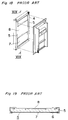
- a door main body 4 includes an integral door frame 5 forming upper and lower sides and opposite side faces of the door, a door outer plate 6 fixed to the front face of the door frame 5, an expanded heat insulating material 7 of polyurethane foam or the like expanded into a space defined by the door frame 5 and the door outer plate 6, and a reinforcing plate 8 disposed at the reverse face side of the door frame 5 and subjected to integral expansion with the heat insulating material 7 so as to be held in place by the bonding force of said expanded heat insulating material 7.
- FIGs. 20 and 21 one example of a heat insulating door of the conventional refrigerators described so far will be explained hereinbelow.
- the heat insulating door generally includes an outer panel 9 formed by applying a decorative film 9d of 0.1 mm thick composed of a transparent layer 9b and a printed layer 9c, onto an iron plate 9a by a bonding agent 9e, an inner plate 10 disposed to confront said outer panel 9, a frame member 11 having an outer panel inserting portion 11a of a generally U-shaped cross section for application over an entire outer peripheral portion of the outer panel 11, an insulating material 12 filled through expansion into a space defined by the outer panel 9, the inner plate 10 and the frame member 11, and a reinforcing member 13 of a U-shaped cross section inserted in the frame member 11 at the side of the heat insulating material 12.
- the surface of the outer panel tends to be formed with undulation instead of being flat, due to the facts that when the decorative film is applied onto the iron plate, bubbles and dust, etc. are apt to be confined, concave and convex portions of the bonding agent or undulation on the surface of the iron plate, etc. tend to be undesirably picked up.
- the bonding agent is separated to be raised due to difference in the linear expansion coefficients between the iron plate and the decorative film, thus forming the undulation on the surface of the heat insulating door.
- Another disadvantage of the conventional arrangements is that the outer panel for the insulating door tends to be formed with undulation by the heat insulating material filled through expansion in the door.
- an essential object of the present invention is to provide a heat insulating door wall structure for a refrigerator or the like, in which formation of very small undulation, waving or the like on the surface of the heat insulating door is prevented to provide a door construction with a high degree of luster.
- Another object of the present invention is to provide a heat insulating door wall structure of the above described type which is simple in construction with a high durability, and can be readily manufactured at low cost.
- a heat insulating door wall structure which includes a transparent plate member, a frame member provided on an entire portion of the transparent plate member, an inner plate provided to confront the transparent plate member, and an insulating material filled through expansion in a space defined by the transparent plate member, the frame member and the inner plate.
- the surface of the door by constituting the surface of the door with a colored glass plate or the like having a transparent layer at its front surface and a colored layer at its reverse surface, deep luster is provided by the transparent glass plate located before the colored layer, while owing to high rigidity of the glass plate, undulation to be formed on the front surface of the door by contraction of an insulating material filled through expansion or foaming or by warping of the door due to temperature difference between exterior and interior of the door, is advantageously prevented and moreover, by increasing the strength of the door, reinforcing members for the door can be dispensed with for simple construction and reduction in cost.
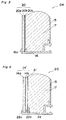
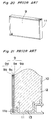
- a heat insulating door D1 which includes a door surface colored plate member or colored glass plate 14 having a transparent layer 14a at a front surface and a colored layer 14b fused onto a reverse surface of the transparent layer 14a, a frame member 16 having a colored glass plate inserting portion 16a formed on an entire peripheral portion thereof, an inner plate 15 provided to confront the colored glass plate 14 through a space, and a heat insulating material 17 filled, through expansion, in the space defined by the colored glass plate 14, the inner plate 15 and the frame member 16.
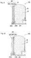
- FIG.3 there is shown a heat insulating door D2 according to a second embodiment of the present invention.
- the colored glass plate 14 described as employed in the first embodiment of Figs.1 and 2 has been replaced by a glass decorative plate 18 having a transparent layer 18a at the front face, a transfer printing layer 18b provided at its reverse face side, and a print protective layer 18c provided at the back of said transfer printing layer 18b, while other constructions of the heat insulating door D2 are generally similar to those in the heat insulating door D1 in Figs. 1 and 2, with like parts being designated by like reference numerals for brevity of explanation.
- the colored glass plate 14 in the first embodiment of Figs. 1 and 2 has been replaced by a reinforced colored glass plate 19 having a transparent reinforced glass layer 19a at the front surface, and a colored layer 19b at the reverse surface, while other constructions are generally similar to those in the door D1 of the first embodiment, with like parts being designated by like reference numerals for brevity.
- FIG. 5 there is shown a heat insulating door D4 according to a fourth embodiment of the present invention, in which the colored glass plate 14 described as employed in the door D1 of the first embodiment has been replaced by a reinforced decorative glass plate 20 having a transparent glass layer 20a at the front surface, a transfer printing layer 20b provided at the reverse surface side of the reinforced glass layer 20, and a printing protective layer 20c provided at the back of the transfer printing layer 20.
- a reinforced decorative glass plate 20 having a transparent glass layer 20a at the front surface, a transfer printing layer 20b provided at the reverse surface side of the reinforced glass layer 20, and a printing protective layer 20c provided at the back of the transfer printing layer 20.
- Other constructions are generally similar to those in the door D1 of the first embodiment, with like parts being designated by like reference numerals for brevity.
- FIG.6 there is shown a heat insulating door D5 according to a fifth embodiment of the present invention.
- the heat insulating door D5 generally includes a colored glass plate 14' having a transparent layer 14a at the front surface and a colored layer 14b at the reverse face side, an outer plate 21 of an iron plate disposed at the reverse face side of the colored glass plate 14', a frame member 22 having a glass plate inserting portion 22a and an outer plate inserting portion 22b in a generally E-shaped cross section for fitting over entire peripheral portions of the colored glass plate 14' and the outer plate 21, an inner plate 15 provided to confront the outer plate 21, and a heat insulating material 17 filled, through expansion, in a space defined by the outer plate 21, the frame member 22, and the inner plate 15.
- Fig. 7 shows a heat insulating door D6 according to a sixth embodiment of the present invention, in which the colored glass plate 14' described as employed in the heat insulating door D5 for the fifth embodiment has been replaced by a glass decorative plate 18' having a transparent layer 18a at the front face, a transfer printing layer 18b provided at its reverse face side, and a print protective layer 18c provided at the back of the transfer printing layer 18b. Since other constructions of the heat insulating door D6 are generally similar to those of the door D5 of Fig. 6, detailed description thereof has been abbreviated here for brevity, with like parts being designated by like reference numerals.
- a heat insulating door D7 in Fig. 8 according to a seventh embodiment of the present invention, the colored glass plate 14' in the heat insulating door D5 of the fifth embodiment in Fig. 6 has been replaced by a reinforced colored glass plate 19' having a transparent reinforced glass layer 19a at the front surface, and a colored layer 19b at the reverse surface, while other constructions are generally similar to those in the door D5 of the fifth embodiment, with like parts being designated by like reference numerals for brevity.
- FIG. 9 there is shown a heat insulating door D8 according to an eighth embodiment of the present invention, in which the colored glass plate 14' described as employed in the door D5 of the fifth embodiment has been replaced by a reinforced decorative glass plate 20' having a transparent reinforced glass layer 20a at the front surface, a transfer printing layer 20b provided at the reverse surface side of the reinforced glass layer 20a, and a printing protective layer 20c provided at the back of the transfer printing layer 20b.
- Other constructions are generally similar to those in the door D5 of the fifth embodiment, with like parts being designated by like reference numerals for brevity.
- a heat insulating door D9 which includes a transparent glass plate 23, an outer plate 24 having an iron plate 24a and a printing portion 24b and disposed at the reverse face side of the glass plate 23, a frame member 25 having a glass plate inserting portion 25a and an outer plate inserting portion 25b generally in an E-shaped cross section for fitting onto the entire outer peripheral portion of the glass plate 23 and the outer plate 24, an inner plate 15 provided to confront the outer plate 24, and a heat insulating material 17 filled through expansion, in a space defined by the outer plate 24, the frame member 25, and the inner plate 15.
- Fig. 11 shows a heat insulating door D10 according to a tenth embodiment of the present invention, in which the glass plate 23 described as employed in the heat insulating door D9 for the ninth embodiment in Fig. 10 has been replaced by a transparent reinforced glass plate 26. Since other constructions of the heat insulating door D10 are generally similar to those of the door D9 of Fig. 10, detailed description thereof has been abbreviated here for brevity, with like parts being designated by like reference numerals.
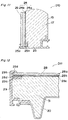
- FIGs. 12 to 15 there is shown constructions of a heat insulating door D11 for use in a refrigerator or the like according to an eleventh embodiment of the present invention.
- the heat insulating door D11 generally includes an outer plate 28 having a glass plate 28a at a front face, a colored layer 28b colored or formed with patterns by transfer printing over the reverse surface of the glass plate 28a, a protective layer 28c formed on the colored layer 28b, a chamfered portion 28d formed around the outer peripheral edge of the outer plate 28, a door frame member 29 fixed to the outer periphery of the outer plate 28, an outer plate inserting groove 29 a having approximately an U-shaped cross section so as to be fitted over the edges to the outer plate 28, a flexible member 29b integrally formed with the door frame 29 and contacting the outer peripheral portion of the outer plate 28, a door inner plate 30 formed by vacuum molding by resin, and supported at its entire periphery by the door frame 29 through a predetermined distance from the outer plate 28 and a heat insulating material 31 filled through expansion, in a space defined by the door inner plate 30, the door frame 29, and the outer plate 28.
- the outer plate 28 is constituted by the glass plate 28a
- appearance on the surface of the heat insulating door D11 may be improved by the luster and flatness of the glass plate 28a, while higher strength of the door is achieved by the hardness of such glass plate, and thus, the reinforcing members conventionally required may be dispensed with for reduction in cost.
- the undulation or waving on the surface of the outer plate 28 by the contraction of the expanded heat insulating material 31 can be advantageously prevented.
- the chamfered portion 28d formed on the outer plate 28 safety during assembling, and improvement in the efficiency for insertion of the outer plate 28 into the outer plate inserting groove 29a of the door frame member 29 can be achieved. Meanwhile, by the flexible member 29b formed in the door frame member 29, the outer peripheral portion of the outer plate 28 is protected, and thus, cracking form the end face of the glass plate 28a by the impact to the outer plate 28 may be prevented.
Landscapes
- Engineering & Computer Science (AREA)
- Civil Engineering (AREA)
- Structural Engineering (AREA)
- Chemical & Material Sciences (AREA)
- Combustion & Propulsion (AREA)
- Physics & Mathematics (AREA)
- Mechanical Engineering (AREA)
- Thermal Sciences (AREA)
- General Engineering & Computer Science (AREA)
- Refrigerator Housings (AREA)
Abstract
Description
- The present invention generally relates to a heat insulating door, and more particularly, to a heat insulating door wall structure for use in a refrigerator or the like.
- Recently, in order to improve design quality, a heat insulating door for a refrigerator has been increased in the number of its colors, with a luster imparted to the colors. Moreover, it has been a tendency to deepen the luster for further improvement of its design characteristics.
- With respect to the technique related to the door wall material as referred to above, there has conventionally been proposed an arrangement as disclosed, for example, in Japanese Patent Laid-Open Publication Tokkaisho No. 61-116267 and schematically shown in Fig. 16, in which the refrigerator includes an outer casing or
housing 1 of a rectangular box-like configuration, withdoors housing 1 for selective closing or opening of saidhousing 1. The surface of each of thedoors - Meanwhile, in Figs. 17 to 19, there is shown a door construction as disclosed in Japanese Utility Model Publication Jikkosho No. 54-17555, in which a door
main body 4 includes anintegral door frame 5 forming upper and lower sides and opposite side faces of the door, a doorouter plate 6 fixed to the front face of thedoor frame 5, an expandedheat insulating material 7 of polyurethane foam or the like expanded into a space defined by thedoor frame 5 and the doorouter plate 6, and a reinforcingplate 8 disposed at the reverse face side of thedoor frame 5 and subjected to integral expansion with theheat insulating material 7 so as to be held in place by the bonding force of said expandedheat insulating material 7. - In the conventional arrangement as described with reference to Fig. 16, however, there have been such problems that, in the surfaces of the
doors doors - When the reinforcing
plate 8 is provided as shown in Fig. 19 for preventing warping of the door due to the temperature difference as described above, there have also been such problems that not only the higher cost may result, but waving is produced on the surface of the doorouter plate 6 by the contraction arising from the expandedheat insulating material 7 between the reinforcingplate 8 and the doorouter plate 6. - As another conventional heat insulating door of this kind, there may be raised a heat insulating door for a refrigerator with a model number "NR-F46K1" manufactured by Matsushita Refrigeration Company and put on sale in February, 1990.
- Referring to Figs. 20 and 21, one example of a heat insulating door of the conventional refrigerators described so far will be explained hereinbelow.
- In Figs. 20 and 21, the heat insulating door generally includes an
outer panel 9 formed by applying adecorative film 9d of 0.1 mm thick composed of atransparent layer 9b and a printedlayer 9c, onto an iron plate 9a by abonding agent 9e, aninner plate 10 disposed to confront saidouter panel 9, aframe member 11 having an outerpanel inserting portion 11a of a generally U-shaped cross section for application over an entire outer peripheral portion of theouter panel 11, aninsulating material 12 filled through expansion into a space defined by theouter panel 9, theinner plate 10 and theframe member 11, and a reinforcingmember 13 of a U-shaped cross section inserted in theframe member 11 at the side of theheat insulating material 12. - In the known arrangement as described above, however, although the luster is given by the decorative film, a sufficient depth is not provided in the luster, since the decorative film can not be made thick.
- Moreover, the surface of the outer panel tends to be formed with undulation instead of being flat, due to the facts that when the decorative film is applied onto the iron plate, bubbles and dust, etc. are apt to be confined, concave and convex portions of the bonding agent or undulation on the surface of the iron plate, etc. tend to be undesirably picked up.
- Meanwhile, when the heat insulating door is subjected to cooling or heating, the bonding agent is separated to be raised due to difference in the linear expansion coefficients between the iron plate and the decorative film, thus forming the undulation on the surface of the heat insulating door.
- Another disadvantage of the conventional arrangements is that the outer panel for the insulating door tends to be formed with undulation by the heat insulating material filled through expansion in the door.
- Accordingly, an essential object of the present invention is to provide a heat insulating door wall structure for a refrigerator or the like, in which formation of very small undulation, waving or the like on the surface of the heat insulating door is prevented to provide a door construction with a high degree of luster.
- Another object of the present invention is to provide a heat insulating door wall structure of the above described type which is simple in construction with a high durability, and can be readily manufactured at low cost.
- In accomplishing these and other objects, according to one preferred embodiment of the present invention, there is provided a heat insulating door wall structure which includes a transparent plate member, a frame member provided on an entire portion of the transparent plate member, an inner plate provided to confront the transparent plate member, and an insulating material filled through expansion in a space defined by the transparent plate member, the frame member and the inner plate.
- More specifically, by constituting the surface of the door with a colored glass plate or the like having a transparent layer at its front surface and a colored layer at its reverse surface, deep luster is provided by the transparent glass plate located before the colored layer, while owing to high rigidity of the glass plate, undulation to be formed on the front surface of the door by contraction of an insulating material filled through expansion or foaming or by warping of the door due to temperature difference between exterior and interior of the door, is advantageously prevented and moreover, by increasing the strength of the door, reinforcing members for the door can be dispensed with for simple construction and reduction in cost.
- These and other objects and features of the present invention will become apparent from the following description taken in conjunction with the preferred embodiments thereof with reference to the accompanying drawings, in which:
- Fig. 1 is a perspective view of a heat insulating door according to one preferred embodiment of the present invention,
- Fig. 2 is a fragmentary cross sectional view showing an enlarged scale, part of the heat insulating door of Fig. 1,
- Fig. 3 is a cross sectional view similar to Fig. 2, which particularly relates to a second embodiment of the present invention,
- Fig. 4 is a cross sectional view similar to Fig. 2, which particularly relates to a third embodiment of the present invention,
- Fig. 5 is a cross sectional view similar to Fig. 2, which particularly relates to a fourth embodiment of the present invention,
- Fig. 6 is a cross sectional view similar to Fig. 2, which particularly relates to a fifth embodiment of the present invention,
- Fig. 7 is a cross sectional view similar to Fig. 2, which particularly relates to a sixth embodiment of the present invention,
- Fig. 8 is a cross sectional view similar to Fig. 2, which particularly relates to a seventh embodiment of the present invention,
- Fig. 9 is a cross sectional view similar to Fig. 2, which particularly relates to an eighth embodiment of the present invention,
- Fig. 10 is a cross sectional view similar to Fig. 2, which particularly relates to a ninth embodiment of the present invention,
- Fig. 11 is a cross sectional view similar to Fig. 2, which particularly relates to a tenth embodiment of the present invention,
- Fig. 12 is a fragmentary top plan sectional view showing on an enlarged scale, part of a heat insulating door according to an eleventh embodiment of the present invention taken along the line XII-XII in Fig. 13,
- Fig. 13 is a perspective view showing an entire appearance of the heat insulating door of Fig. 12,
- Fig 14 is a perspective view of an outer plate employed in the heat insulating door of Fig. 12,
- Fig. 15 is a fragmentary side sectional view showing on an enlarged scale, part of the outer plate of Fig. 14,
- Fig. 16 is a perspective view of a refrigerator provided with conventional heat insulating doors (already referred to),
- Fig. 17 is a perspective view showing one example of a conventional heat insulating door (already referred to),
- Fig. 18 is an expoded perspective view of the conventional heat insulating door (already referred to),
- Fig. 19 is a cross section taken along the line XIX-XIX in Fig. 18 (already referred to),
- Fig. 20 is a perspective view of another conventional heat insulating door (already referred to), and
- Fig. 21 is a fragmentary cross sectional view showing on an enlarged scale, part of the conventional heat insulating door of Fig. 20 (already referred to).
- Before the description of the present invention proceeds, it is to be noted that like parts are designated by like reference numerals throughout the accompanying drawings.
- Referring now to the drawings, there is shown in Figs. 1 and 2, a heat insulating door D1 according to a first embodiment of the present invention, which includes a door surface colored plate member or
colored glass plate 14 having a transparent layer 14a at a front surface and acolored layer 14b fused onto a reverse surface of the transparent layer 14a, aframe member 16 having a colored glassplate inserting portion 16a formed on an entire peripheral portion thereof, aninner plate 15 provided to confront thecolored glass plate 14 through a space, and aheat insulating material 17 filled, through expansion, in the space defined by thecolored glass plate 14, theinner plate 15 and theframe member 16. - By the heat insulating door D1 according to the first embodiment as described above, effects as follows can be obtained.
- (1) Luster is provided by the
colored glass plate 14 having the transparent layer 14a on its front surface, and thecolored layer 14b at the reverse surface, while depth may be imparted to the luster. - (2) Since the surface of the door D1 is constituted by a single part, it is not necessary to apply a decorative film onto the iron plate as in the conventional practice, and thus, there in no possibility of confining bubbles, dust, etc., or forming undulation or concave and convex portions on the surface of the iron plate by the bonding agent, and therefore, the surface of the heat insulating door D1 is free from undulation.
- (3) Owing to the fact that the surface of the door D1 is made of the single part, there is no possibility that the bonding agent is separated and raised by the difference of linear expansion coefficients upon application of cooling and heating to the heat insulating door.
- (4) Since the surface of the heat insulating door D1 made of the
glass plate 14 has rigidity, it is not subjected to undulation by theheat insulating material 17 filled through expansion, and thus, the surface of the heat insulating door D1 is free from concave and convex portions. - (5) Although there is a possibility that the surface of the heat insulating door D1 made of the glass plate is broken, the expanded
heat insulating material 17 provided at reverse face side of the glass plate absorbs shock when external force is applied to the glass plate, while the edges of the glass plate which are the weakest portion are protected by theframe member 16 so as to be free from breakage. - (6) When the
heat insulating material 17 is to be expanded, it slides along the back face of thecolored layer 14b of theglass plate 14 for efficient filling. - (7) Since the
glass plate 14 has rigidity, the reinforcing plate conventionally provided in the heat insulating door may be dispensed with. - Referring to Fig.3, there is shown a heat insulating door D2 according to a second embodiment of the present invention. In this second embodiment, the
colored glass plate 14 described as employed in the first embodiment of Figs.1 and 2 has been replaced by a glassdecorative plate 18 having atransparent layer 18a at the front face, atransfer printing layer 18b provided at its reverse face side, and a printprotective layer 18c provided at the back of saidtransfer printing layer 18b, while other constructions of the heat insulating door D2 are generally similar to those in the heat insulating door D1 in Figs. 1 and 2, with like parts being designated by like reference numerals for brevity of explanation. - In the above heat insulating door D2, in addition to the effect available from the door D1 of the first embodiment, there is another effect that various kinds of designs may be dealt with by the transfer printing.
- In a heat insulating door D3 in Fig. 4 according to a third embodiment of the present invention, the
colored glass plate 14 in the first embodiment of Figs. 1 and 2 has been replaced by a reinforcedcolored glass plate 19 having a transparentreinforced glass layer 19a at the front surface, and acolored layer 19b at the reverse surface, while other constructions are generally similar to those in the door D1 of the first embodiment, with like parts being designated by like reference numerals for brevity. - In the heat insulating door D3 according to a third embodiment of the present invention, in addition to the effect available from the door D1 in the first embodiment, durability is further improved by using the reinforced glass, while safety is achieved even when the glass should be broken.
- Referring also to Fig. 5, there is shown a heat insulating door D4 according to a fourth embodiment of the present invention, in which the
colored glass plate 14 described as employed in the door D1 of the first embodiment has been replaced by a reinforceddecorative glass plate 20 having a transparent glass layer 20a at the front surface, atransfer printing layer 20b provided at the reverse surface side of thereinforced glass layer 20, and a printingprotective layer 20c provided at the back of thetransfer printing layer 20. Other constructions are generally similar to those in the door D1 of the first embodiment, with like parts being designated by like reference numerals for brevity. - In the heat insulating door D4 according to a fourth embodiment of the present invention,in addition to the effect available from the door D2 in the second embodiment, there are also obtained such effects that durability is further improved by the employment of the reinforced glass, and safety is maintained even upon breakage of the glass.
- Referring further to Fig.6, there is shown a heat insulating door D5 according to a fifth embodiment of the present invention.
- The heat insulating door D5 generally includes a colored glass plate 14' having a transparent layer 14a at the front surface and a
colored layer 14b at the reverse face side, anouter plate 21 of an iron plate disposed at the reverse face side of the colored glass plate 14', aframe member 22 having a glass plate inserting portion 22a and an outerplate inserting portion 22b in a generally E-shaped cross section for fitting over entire peripheral portions of the colored glass plate 14' and theouter plate 21, aninner plate 15 provided to confront theouter plate 21, and aheat insulating material 17 filled, through expansion, in a space defined by theouter plate 21, theframe member 22, and theinner plate 15. - By the heat insulating door D5 according to the fifth embodiment of the present invention as described above, effects as follows may be achieved.
- (1) Luster is provided by the glass plate 14' located before the printing portion, while depth may be imparted to the luster.
- (2) Since the surface of the door D5 is constituted by a single part without being bonded together, it is not necessary to apply a decorative film onto the iron plate as in the conventional practice, and thus, there in no possibility of confining bubbles, dust, etc., or forming undulation or concave and convex portions on the surface of the iron plate by the bonding agent, and accordingly, the surface of the heat insulating door D5 is free from undulation.
- (3) Owing to the fact that the surface of the door is made of a single part, there is no possibility that the bonding agent is separated and raised by the difference of linear expansion coefficients upon application of cooling and heating to the heat insulating door.
- (4) Since the
outer plate 21 is provided at the back of the glass plate 14' for the front surface of the heat insulating door D5, the undulation to be formed by theheat insulating material 17 filled through expansion is stopped at theouter plate 21, and thus, there is no possibility that undulation is formed on the front surface of the heat insulating door D5. - (5) Although there is a possibility that the surface of the heat insulating door D5 made of the glass plate 14' is broken, the expanded
heat insulating material 17 provided at reverse face side of the glass plate absorbs shock when external force is applied to the glass plate, and thus, breakage of the glass plate is prevented. - (6) Since the glass plate 14' has rigidity, the reinforcing members conventionally included in the heat insulating door may be dispensed with.
- (7) Owing to the construction that the
frame member 22 has the glass plate inserting portion 22a and the outerplate inserting portion 22b generally in the E-shaped cross section, the colored glass plate may be simply replaced through mere fitting or removing. - Fig. 7 shows a heat insulating door D6 according to a sixth embodiment of the present invention, in which the colored glass plate 14' described as employed in the heat insulating door D5 for the fifth embodiment has been replaced by a glass decorative plate 18' having a
transparent layer 18a at the front face, atransfer printing layer 18b provided at its reverse face side, and a printprotective layer 18c provided at the back of thetransfer printing layer 18b. Since other constructions of the heat insulating door D6 are generally similar to those of the door D5 of Fig. 6, detailed description thereof has been abbreviated here for brevity, with like parts being designated by like reference numerals. - In the above heat insulating door D6, in addition to the effect available from the door D5 of the fifth embodiment, there is another effect that various kinds of designs may be dealt with by the transfer printing.
- In a heat insulating door D7 in Fig. 8 according to a seventh embodiment of the present invention, the colored glass plate 14' in the heat insulating door D5 of the fifth embodiment in Fig. 6 has been replaced by a reinforced colored glass plate 19' having a transparent reinforced
glass layer 19a at the front surface, and acolored layer 19b at the reverse surface, while other constructions are generally similar to those in the door D5 of the fifth embodiment, with like parts being designated by like reference numerals for brevity. - In the heat insulating door D7 according to the seventh embodiment of the present invention, in addition to the effect available from the door D5 in the fifth embodiment, durability is further improved by using the reinforced glass 19', while safety is achieved even when the glass should be broken.
- Referring also to Fig. 9, there is shown a heat insulating door D8 according to an eighth embodiment of the present invention, in which the colored glass plate 14' described as employed in the door D5 of the fifth embodiment has been replaced by a reinforced decorative glass plate 20' having a transparent reinforced glass layer 20a at the front surface, a
transfer printing layer 20b provided at the reverse surface side of the reinforced glass layer 20a, and a printingprotective layer 20c provided at the back of thetransfer printing layer 20b. Other constructions are generally similar to those in the door D5 of the fifth embodiment, with like parts being designated by like reference numerals for brevity. - In the heat insulating door D8 according to an eighth embodiment of the present invention,in addition to the effect available from the door D5 in the fifth embodiment, there are also obtained such effects that durability is further improved by the employment of the reinforced glass, and safety is maintained even upon breakage of the glass.
- Referring further to Fig. 10, there is shown a heat insulating door D9 according to a ninth embodiment of the present invention, which includes a
transparent glass plate 23, anouter plate 24 having aniron plate 24a and aprinting portion 24b and disposed at the reverse face side of theglass plate 23, aframe member 25 having a glass plate inserting portion 25a and an outerplate inserting portion 25b generally in an E-shaped cross section for fitting onto the entire outer peripheral portion of theglass plate 23 and theouter plate 24, aninner plate 15 provided to confront theouter plate 24, and aheat insulating material 17 filled through expansion, in a space defined by theouter plate 24, theframe member 25, and theinner plate 15. - By the heat insulating door D9 according to the ninth embodiment of the present invention as described above, effect as follows can be obtained.
- (1) Luster is provided by the glass plate located before the printing portion, while depth may be imparted to the luster.
- (2) Since the surface of the door D9 is constituted by a single part, without being bonded together, it is not necessary to apply a decorative film onto the iron plate or in the conventional practice, and thus, there is no possibility of confining bubbles, dust, etc., or forming undulation by the bonding agent or concave and convex portions on the surface of the iron plate, and therefore, the surface of the heat insulating door D9 is free from undulation.
- (3) Owing to the fact that the surface of the door D9 is made of the single part, there is no possibility that the bonding agent is separated and raised by the difference of linear expansion coefficients upon application of cooling and heating to the heat insulating door D9.
- (4) Since the
outer plate 15 is provided at the back of the glass plate for the front surface of the heat insulating door D9, the undulation to be formed by theheat insulating material 17 filled through expansion is stopped at theouter plate 15, and thus, there is no possibility that undulation is formed on the front surface of the heat insulating door. - (5) Although there is a possibility that the surface of the heat insulating door D9 made of
glass plate 23 is broken, the expandedheat insulating material 17 provided at the reverse face side of theglass plate 23 absorbs shock when external force is applied to the glass plate, and thus, breakage of the glass plate is prevented. - (6) Since the
glass plate 23 has rigidity, the reinforcing members conventionally included in the heat insulating door may be dispensed with. - Fig. 11 shows a heat insulating door D10 according to a tenth embodiment of the present invention, in which the
glass plate 23 described as employed in the heat insulating door D9 for the ninth embodiment in Fig. 10 has been replaced by a transparent reinforcedglass plate 26. Since other constructions of the heat insulating door D10 are generally similar to those of the door D9 of Fig. 10, detailed description thereof has been abbreviated here for brevity, with like parts being designated by like reference numerals. - In the heat insulating door D10 according the tenth embodiment of the present invention, in addition to the effect available from the door D9 in the ninth embodiment, durability is further improved by using the reinforced glass, while safety is achieved even when the glass should be broken.
- Referring further to Figs. 12 to 15, there is shown constructions of a heat insulating door D11 for use in a refrigerator or the like according to an eleventh embodiment of the present invention.
- In Figs.12 to 15, the heat insulating door D11 generally includes an
outer plate 28 having a glass plate 28a at a front face, acolored layer 28b colored or formed with patterns by transfer printing over the reverse surface of the glass plate 28a, aprotective layer 28c formed on thecolored layer 28b, a chamferedportion 28d formed around the outer peripheral edge of theouter plate 28, adoor frame member 29 fixed to the outer periphery of theouter plate 28, an outer plate inserting groove 29 a having approximately an U-shaped cross section so as to be fitted over the edges to theouter plate 28, aflexible member 29b integrally formed with thedoor frame 29 and contacting the outer peripheral portion of theouter plate 28, a doorinner plate 30 formed by vacuum molding by resin, and supported at its entire periphery by thedoor frame 29 through a predetermined distance from theouter plate 28 and aheat insulating material 31 filled through expansion, in a space defined by the doorinner plate 30, thedoor frame 29, and theouter plate 28. - In the above arrangement of the heat insulating door D11, since the
outer plate 28 is constituted by the glass plate 28a, appearance on the surface of the heat insulating door D11 may be improved by the luster and flatness of the glass plate 28a, while higher strength of the door is achieved by the hardness of such glass plate, and thus, the reinforcing members conventionally required may be dispensed with for reduction in cost. Moreover, the undulation or waving on the surface of theouter plate 28 by the contraction of the expandedheat insulating material 31 can be advantageously prevented. Owing to the arrangement that thecolored layer 28b and theprotective layer 28c are formed on the reverse surface of the glass plate 28a, design effect on the surface of theouter plate 28 can be achieved by thecoloring layer 28b, while heat influence to thecolored layer 28b during expansion of theheat insulating material 31, and damages to thecolored layer 28b during assembling are prevented by the presence of theprotective layer 28c. - Furthermore, by the chamfered
portion 28d formed on theouter plate 28, safety during assembling, and improvement in the efficiency for insertion of theouter plate 28 into the outer plate inserting groove 29a of thedoor frame member 29 can be achieved. Meanwhile, by theflexible member 29b formed in thedoor frame member 29, the outer peripheral portion of theouter plate 28 is protected, and thus, cracking form the end face of the glass plate 28a by the impact to theouter plate 28 may be prevented. - Additionally, since the expanded
heat insulating material 31 is held in close contact with theouter plate 28, there is no possibility of cracking, even if external forces or impacts are applied to theouter plate 28, and even when cracking takes place, scattering of glass pieces is advantageously prevented. - Although the present invention has been fully described by way of example with reference to the accompanying drawings, it is to be noted here that various changes and modifications will be apparent to those skilled in the art. Therefore, unless otherwise such changes and modifications depart from the scope of the present invention, they should be construed as included therein.
Claims (28)
- A heat insulating door wall structure which comprises a door surface colored plate member, a frame member (16) provided on an entire peripheral portion of said door surface colored plate member, an inner plate (15) provided to confront said door surface colored plate member through an interval, and a heat insulating material (17) filled, through expansion, in a space defined by said door surface colored plate member, said frame member (16) and said inner plate (15) within said door wall structure,
- A heat insulating door wall structure as claimed in claim 1, wherein said door surface colored plate member includes a transparent plate member (14a) at its front surface, and a colored layer (14b) provided as a reverse surface of said transparent plate member (14a).
- A heat insulating door wall structure as claimed in Claim 2, wherein said door surface colored plate member is of a glass decorative plate (18) including a transparent layer (18a) at its front surface, a transfer printing layer (18a) provided at a reverse surface of the transparent layer (18b), and a printing protective layer (18c) further provided at a reverse surface of said transfer printing later (18b).
- A heat insulating door wall structure as claimed in Claim 2, wherein said door surface colored plate member is of a reinforced colored glass plate (19) including a transparent reinforced glass layer (19a) at its front surface, and colored layer (19b) at a reverse surface of said transparent reinforced glass layer (19a).
- A heat insulating door wall structure as claimed in Claim 2, wherein said door surface colored plate member is of a reinforced colored glass plate (20) including a transparent reinforced glass layer (20a) at its front surface, a transfer printing layer (20b) at a reverse surface of said transparent reinforced glass layer (20a), and a printing protective layer (20c) further provided at a reverse surface of said transfer printing layer (20b).
- A heat insulating door wall structure which comprises a door surface plate member having a transparent plate member (14a) and a colored layer (14b) at its reverse surface, an outer plate (21) disposed at a reverse surface side of said door surface plate member, a frame member (22) provided on an entire peripheral portion of said door surface plate member and said outer plate (21), an inner plate (15) provided to confront said outer plate (21), and a heat insulating member (17) filled, through expansion, in a space defined by said outer plate (21), said frame member (22) and said inner plate (15) within said door wall structure.
- A heat insulating door wall structure as claimed in Claim 6, wherein said door surface plate member is of a decorative plate (18') including a transparent layer (18a) at its front surface, a transfer printing layer (18b) provided at a reverse surface of the transparent layer (18a), and a printing protective layer (18c) further provided at a reverse surface of said transfer printing layer (18b).
- A heat insulating door wall structure as claimed in Claim 6, wherein said door surface plate member is of a reinforced colored glass plate (19') including a transparent reinforced glass layer (19a) at its front surface, and a colored layer (19b) at a reverse surface of said transparent reinforced glass layer (19a).
- A heat insulating door wall structure as claimed in Claim 6, wherein said door surface plate member is of a glass decorative plate (20') including a transparent reinforced glass layer (20a) at its front surface, a transfer printing layer (20b) at a reverse surface of said transparent reinforced glass layer (20a), and a printing protective layer (20c) further provided at a reverse surface of said transfer printing layer (20b).
- A heat insulating door wall structure which comprises a transparent glass plate (23) provided at a front surface of the door, an outer plate (24) disposed at a reverse surface side of said glass plate (23) and including and iron plate (24a) applied with a printed portion (24b), a frame member (25) provided on an entire peripheral portion of said plate (23) and said outer plate (24), an inner plate (15) provided to confront said outer plate (24) and a heat insulating member (17) filled, through expansion in a space defined by said outer plate (24), said frame member (25) and said inner plate (15) within said door wall structure.
- A heat insulating door wall structure as claimed in Claim 10, wherein said transparent glass plate (23) is of a transparent reinforced glass plate (26).
- A heat insulating door wall structure which comprises an outer plate (28) including a transparent plate member (28a) having a colored layer (28b) formed on its reverse surface, and a protective film (28c) formed to protect said colored layer (28b), a door frame member (29) fixed onto an entire peripheral portion of said outer plate (28), a door inner plate (30) mounted through a predetermined distance from said outer plate (28), and an expanded heat insulating material (31) filled, through expansion, in a space defined by said door inner plate (30), said outer plate (28) and said door frame member (29).
- A heat insulating door wall structure claimed in Claim 12, wherein said door frame member (29) is molded by a hard resin, and further includes a flexible member (29b) integrally formed as part of said door frame member (29) and adapted to contact the outer peripheral portion of said outer plate (28).
- A heat insulating door wall structure as claimed in Claim 12, wherein said outer plate (28) is chamfered at its outer peripheral portion.
- A refrigerator provided with a heat insulating door wall structure which comprises a door surface colored plate member, a frame member (16) provided on an entire peripheral portion of said door surface colored plate member, an inner plate (15) provided to confront said door surface colored plate member though an interval, and a heat insulating material (17) filled, though expansion, in a space defined by said door surface colored plate member, said frame member (16) and said inner plate (15) within said door wall structure.
- A refrigerator as claimed in Claim 15, wherein said door surface colored plated member includes a transparent plate member (14a) at its front surface, and a colored layer (14b) provided at a reverse surface of said transparent plate member (14a).
- A refrigerator as claimed in Claim 16, wherein said door surface colored plate member is of a glass decorative plate (18) including a transparent layer (18a) at its front surface, a transfer printing layer (18b) provided at a reverse surface of the transparent layer (18a), and a printing protective layer (18c) further provided at a reverse surface of said transfer printing layer (18b).
- A refrigerator as claimed in Claim 16, wherein said door surface colored plate member is of a reinforced colored glass plate (19) including a transparent reinforced glass layer (19a) at its front surface, and a colored layer (19b) at a reverse surface of said transparent reinforced glass layer (19a).
- A refrigerator as claimed in Claim 16, wherein said door surface colored plate member is of a reinforced colored glass plate (20) including a transparent reinforced glass layer (20a) at its front surface, a transfer printing layer (20b) at a reverse surface of said transparent reinforced glass layer (20a), and a printing protective layer (20c) further provided at a reverse surface of said transfer printing layer (20b).
- A refrigerator provided with a heat insulating door wall structure which comprises a door surface plate member having a transparent plate member (14a) and a colored layer (14b) at its reverse surface, an outer plate (21) disposed at a reverse surface side of said door surface plate member, a frame member (22) provided on an entire peripheral portion of said door surface plate member and said outer plate (21), an inner plate (15) provided to confront said outer plate (21), and a heat insulating member (17) filled, through expansion in a space defined by said outer plate (21), said frame member (22) and said inner plate (15) within said door wall structure.
- A refrigerator as claimed in Claim 20, wherein said door surface plate member is of a decorative plate (18') including a transparent layer (18a) at its front surface, a transparent printing layer (18b) provided at a reverse surface of the transparent layer (18a), and a printing protective layer (18c) further provided at a reverse surface of said transfer printing layer (18b).
- A refrigerator as claimed in claim 20, wherein said door surface plate member is of a reinforced colored glass plate (19') including a transparent reinforced glass layer (19a) at its front surface, and a colored layer (19b) at a reverse surface of said transparent reinforced glass layer (19a).
- A refrigerator as claimed in Claim 20, wherein said door surface plate member is of a glass decorative plate (20') including a transparent reinforced glass layer (20a) at its front surface, a transfer printing layer (20b) at a reverse surface of said transparent reinforced glass layer (20a), and a printing protective layer (20c) further provided at a reverse surface of said transfer printing layer (20b).
- A refrigerator provided with a heat insulating door wall structure which comprises a transparent glass plate (23) provided at a front surface of the door, an outer plate (24) disposed at a reverse surface side of said glass plate (23) and including an iron plate (24a) applied with a printed portion (24b), a frame member (25) provided on an entire peripheral portion of said glass plate (23) and said outer plate (24), an inner plate (15) provided to confront said outer plate (24), and a heat insulating member (17) filled, though expansion in a space defined by said outer plate (24), said frame member (25) and said inner plate (15) within said door wall structure.
- A refrigerator as claimed in Claim 24, wherein said transparent glass plate (23) is of a transparent reinforced glass plate (26).
- A refrigerator provided with heat insulating door wall structure which comprises an outer plate (28) including a transparent plate member (28a) having a colored layer (28b) formed on its reverse surface, and a protective film(28c) formed to protect said colored layer (28b), a door frame member (29) fixed onto an entire peripheral portion of said outer plate (28), a door inner plate (30) mounted through a predetermined distance from said outer plate (28), and an expanded heat insulating material (31) filled, through expansion into a space defined by said door inner plate (30), said outer plate (28) and said door frame member (29).
- A refrigerator as claimed in Claim 26, wherein said door frame member (29) is molded by a hard resin, and further includes a flexible member (29b) formed as part of said door frame member (29) and adapted to contact the outer peripheral portion of said outer plate (28).
- A refrigerator as claimed in Claim 25, wherein said outer plate (28) is chamfered at its outer peripheral portion.
Applications Claiming Priority (4)
| Application Number | Priority Date | Filing Date | Title |
|---|---|---|---|
| JP3291166A JPH05126461A (en) | 1991-11-07 | 1991-11-07 | Thermal insulation door |
| JP291166/91 | 1991-11-07 | ||
| JP03296927A JP3140110B2 (en) | 1991-11-13 | 1991-11-13 | Refrigerator door |
| JP296927/91 | 1991-11-13 |
Publications (3)
| Publication Number | Publication Date |
|---|---|
| EP0541109A2 true EP0541109A2 (en) | 1993-05-12 |
| EP0541109A3 EP0541109A3 (en) | 1994-05-11 |
| EP0541109B1 EP0541109B1 (en) | 1998-02-04 |
Family
ID=26558425
Family Applications (1)
| Application Number | Title | Priority Date | Filing Date |
|---|---|---|---|
| EP92119034A Expired - Lifetime EP0541109B1 (en) | 1991-11-07 | 1992-11-06 | Heat insulating door wall structure |
Country Status (5)
| Country | Link |
|---|---|
| US (1) | US5520453A (en) |
| EP (1) | EP0541109B1 (en) |
| JP (1) | JPH05126461A (en) |
| KR (1) | KR100226039B1 (en) |
| DE (1) | DE69224346T2 (en) |
Cited By (14)
| Publication number | Priority date | Publication date | Assignee | Title |
|---|---|---|---|---|
| WO2004015343A1 (en) * | 2002-08-05 | 2004-02-19 | BSH Bosch und Siemens Hausgeräte GmbH | Refrigerator door |
| FR2869635A1 (en) * | 2004-04-28 | 2005-11-04 | Puerta Tht S L | Metal door for e.g. building construction, has F-shaped transversal section profiles disposed around U-shaped plate, and decorative panel whose edge is disposed in housing, formed by blades of profiles, oriented inside door |
| KR100634367B1 (en) | 2005-08-29 | 2006-10-16 | 엘지전자 주식회사 | Refrigerator door having a display |
| CN101858679A (en) * | 2010-06-24 | 2010-10-13 | 宁波华彩电器有限公司 | Refrigerator door with three-dimensional effect picture |
| GB2470064A (en) * | 2009-05-08 | 2010-11-10 | Leaderflush & Shapland Ltd | Door with transparent covering panel |
| EP2472206A1 (en) * | 2007-09-26 | 2012-07-04 | BSH Bosch und Siemens Hausgeräte GmbH | Refrigeration unit |
| WO2012065874A3 (en) * | 2010-11-17 | 2012-10-11 | BSH Bosch und Siemens Hausgeräte GmbH | Refrigeration device door |
| EP2333464A3 (en) * | 2009-12-09 | 2015-01-14 | Samsung Electronics Co., Ltd. | Refrigerator door and refrigerator having the same |
| CN104534791A (en) * | 2014-12-25 | 2015-04-22 | 合肥美的电冰箱有限公司 | Door body of refrigeration plant and refrigeration plant with door body |
| US9339993B2 (en) | 2010-09-14 | 2016-05-17 | Corning Incorporated | Appliance fascia and mounting therefore |
| EP2151645A3 (en) * | 2008-08-05 | 2016-08-31 | Samsung Electronics Co., Ltd. | Door of refrigerator and method for manufacturing the same |
| EP2245401A4 (en) * | 2008-02-21 | 2016-12-21 | Lg Electronics Inc | Refrigerator and refrigerator door |
| CN107024068A (en) * | 2012-09-10 | 2017-08-08 | 松下知识产权经营株式会社 | Freezer |
| CN108981274A (en) * | 2018-05-31 | 2018-12-11 | 东芝家用电器制造(南海)有限公司 | Refrigerator |
Families Citing this family (45)
| Publication number | Priority date | Publication date | Assignee | Title |
|---|---|---|---|---|
| US5909937A (en) * | 1995-03-27 | 1999-06-08 | General Electric Company | Refrigerator door assembly |
| KR100402604B1 (en) * | 2001-09-07 | 2003-10-17 | 주식회사 엘지이아이 | An external decorating member of door for Refrigerator |
| US7055920B2 (en) * | 2001-10-25 | 2006-06-06 | Thetford Corporation | Refrigerator cabinet breaker assembly |
| KR100488074B1 (en) * | 2003-03-22 | 2005-05-06 | 엘지전자 주식회사 | Door structure of refrigerator |
| KR100732040B1 (en) | 2003-09-30 | 2007-06-25 | 엘지전자 주식회사 | Indoor unit of air-conditioner |
| US20110241503A1 (en) * | 2004-01-12 | 2011-10-06 | Lee Simon | Decorative commercial or professional kitchen or food service area appliance unit with interchangeable form fitting cover and a facade panel |
| EP1555497A1 (en) | 2004-01-16 | 2005-07-20 | Electrolux Home Products Corporation N.V. | Refrigerator door construction |
| KR101156286B1 (en) * | 2005-04-20 | 2012-06-13 | 엘지전자 주식회사 | Door for refrigerator |
| US20080042537A1 (en) * | 2005-04-20 | 2008-02-21 | Kim Ung S | Door for Refrigerator |
| KR100678674B1 (en) * | 2005-05-04 | 2007-02-06 | 엘지전자 주식회사 | Front panel mounting structure for door of refrigerator |
| JP5054005B2 (en) * | 2005-07-20 | 2012-10-24 | エルジー エレクトロニクス インコーポレイティド | Refrigerator door and manufacturing method thereof |
| DE102006063088B3 (en) * | 2005-09-23 | 2023-07-06 | Lg Electronics Inc. | refrigerator door |
| US7770985B2 (en) | 2006-02-15 | 2010-08-10 | Maytag Corporation | Kitchen appliance having floating glass panel |
| KR20080033711A (en) * | 2006-10-13 | 2008-04-17 | 엘지전자 주식회사 | An external decorating member for refrigerator and manufacturing method of the same |
| KR101362315B1 (en) * | 2006-06-21 | 2014-02-13 | 엘지전자 주식회사 | A out door for refrigerator and method of manufacturing the same |
| US20090202796A1 (en) * | 2006-06-21 | 2009-08-13 | Ja-Hun Koo | Outcase of refrigerator and method for manufacturing the same |
| US8104853B2 (en) * | 2006-12-19 | 2012-01-31 | Samsung Electronics Co., Ltd. | Refrigerator and method of manufacturing door thereof |
| KR101368290B1 (en) * | 2007-03-08 | 2014-02-26 | 삼성전자주식회사 | Washing machine |
| CA2628517C (en) * | 2007-10-17 | 2013-08-13 | Adm21 Co., Ltd. | Wiper blade with heating elements |
| WO2010060715A2 (en) * | 2008-11-03 | 2010-06-03 | BSH Bosch und Siemens Hausgeräte GmbH | Refrigeration device comprising a glass door |
| DE202009013092U1 (en) * | 2009-09-29 | 2010-03-04 | BSH Bosch und Siemens Hausgeräte GmbH | Refrigerating appliance with a glass door |
| EP2184394A1 (en) * | 2008-11-05 | 2010-05-12 | LG Electronics Inc. | Home appliance and washing machine |
| CN101776364B (en) * | 2009-01-08 | 2014-12-31 | 博西华家用电器有限公司 | Refrigerator |
| KR101602223B1 (en) * | 2009-05-22 | 2016-03-10 | 엘지전자 주식회사 | Eternity panel and refrigerator having the same |
| JP5460207B2 (en) * | 2009-08-12 | 2014-04-02 | 日立アプライアンス株式会社 | refrigerator |
| JP5303415B2 (en) * | 2009-09-28 | 2013-10-02 | 日立アプライアンス株式会社 | refrigerator |
| KR101169671B1 (en) | 2010-04-13 | 2012-08-09 | 에이디엠이십일 주식회사 | Wiper blade with heating elements and method for controling the wiper blade |
| KR101752670B1 (en) * | 2010-08-11 | 2017-07-03 | 삼성전자주식회사 | Refrigerator |
| US8870306B2 (en) * | 2010-12-29 | 2014-10-28 | Lee Simon | Hospitality environment item and method of assembly |
| JP5686651B2 (en) * | 2011-03-30 | 2015-03-18 | 日立アプライアンス株式会社 | refrigerator |
| NL1039440C2 (en) * | 2012-03-06 | 2013-09-09 | Polyplastic Groep B V | COOLING DEVICE AND ACCESS DOOR. |
| KR101307860B1 (en) * | 2012-06-20 | 2013-09-12 | 삼성전자주식회사 | Refrigerator and Method Of Manufacturing Same |
| JP5948184B2 (en) * | 2012-08-27 | 2016-07-06 | 日立アプライアンス株式会社 | refrigerator |
| JP2015052428A (en) * | 2013-09-09 | 2015-03-19 | 日立アプライアンス株式会社 | Refrigerator |
| JP5659281B1 (en) * | 2013-10-09 | 2015-01-28 | 日立アプライアンス株式会社 | refrigerator |
| JP6244195B2 (en) * | 2013-12-19 | 2017-12-06 | 日立アプライアンス株式会社 | refrigerator |
| JP6557859B2 (en) * | 2014-08-29 | 2019-08-14 | パナソニックIpマネジメント株式会社 | refrigerator |
| KR101646378B1 (en) * | 2014-11-11 | 2016-08-05 | 동부대우전자 주식회사 | A refrigerator door frame and a method for manufacturing the same |
| DE102015221885A1 (en) * | 2015-11-06 | 2017-05-24 | BSH Hausgeräte GmbH | Door with a door frame and a handle recess element and household refrigeration appliance with such a door |
| WO2017145252A1 (en) * | 2016-02-23 | 2017-08-31 | 三菱電機株式会社 | Refrigerator door and refrigerator provided with same |
| JP6326450B2 (en) * | 2016-06-02 | 2018-05-16 | 日立アプライアンス株式会社 | refrigerator |
| CN108662824A (en) * | 2017-04-01 | 2018-10-16 | 博西华电器(江苏)有限公司 | Refrigerating appliance and door for refrigerating appliance |
| CN107152836A (en) * | 2017-05-04 | 2017-09-12 | 合肥华凌股份有限公司 | Preparation method, refrigerator door and the refrigerator of refrigerator door |
| US11313611B2 (en) | 2019-05-01 | 2022-04-26 | Whirlpool Corporation | Construction method for vacuum insulated door |
| US11624547B2 (en) | 2021-06-14 | 2023-04-11 | Whirlpool Corporation | Bin attachment assembly for a trim breaker |
Citations (3)
| Publication number | Priority date | Publication date | Assignee | Title |
|---|---|---|---|---|
| FR751491A (en) * | 1933-01-24 | 1933-09-04 | Improvements to lacquered glass wall coverings | |
| GB2186311A (en) * | 1986-02-12 | 1987-08-12 | Hotpoint Ltd | Decorative panels for domestic appliances |
| FR2618481A1 (en) * | 1987-07-24 | 1989-01-27 | Valero Manuel | Improvements in the prodution of doors in furniture |
Family Cites Families (4)
| Publication number | Priority date | Publication date | Assignee | Title |
|---|---|---|---|---|
| US3793756A (en) * | 1972-12-11 | 1974-02-26 | W Kay | Combination litter container and display device |
| DE3634450A1 (en) * | 1986-10-09 | 1988-04-14 | Farmont Rolf | SUNROOF |
| US4732432A (en) * | 1986-12-29 | 1988-03-22 | Whirlpool Corporation | Breaker strip for a refrigerator cabinet |
| US4998382A (en) * | 1989-12-11 | 1991-03-12 | Ardco, Inc. | Insulated refrigerator door assembly with substantially all glass front doors |
-
1991
- 1991-11-07 JP JP3291166A patent/JPH05126461A/en active Pending
-
1992
- 1992-11-06 EP EP92119034A patent/EP0541109B1/en not_active Expired - Lifetime
- 1992-11-06 DE DE69224346T patent/DE69224346T2/en not_active Expired - Fee Related
- 1992-11-07 KR KR1019920020861A patent/KR100226039B1/en not_active IP Right Cessation
-
1994
- 1994-08-10 US US08/288,876 patent/US5520453A/en not_active Expired - Fee Related
Patent Citations (3)
| Publication number | Priority date | Publication date | Assignee | Title |
|---|---|---|---|---|
| FR751491A (en) * | 1933-01-24 | 1933-09-04 | Improvements to lacquered glass wall coverings | |
| GB2186311A (en) * | 1986-02-12 | 1987-08-12 | Hotpoint Ltd | Decorative panels for domestic appliances |
| FR2618481A1 (en) * | 1987-07-24 | 1989-01-27 | Valero Manuel | Improvements in the prodution of doors in furniture |
Cited By (17)
| Publication number | Priority date | Publication date | Assignee | Title |
|---|---|---|---|---|
| WO2004015343A1 (en) * | 2002-08-05 | 2004-02-19 | BSH Bosch und Siemens Hausgeräte GmbH | Refrigerator door |
| FR2869635A1 (en) * | 2004-04-28 | 2005-11-04 | Puerta Tht S L | Metal door for e.g. building construction, has F-shaped transversal section profiles disposed around U-shaped plate, and decorative panel whose edge is disposed in housing, formed by blades of profiles, oriented inside door |
| KR100634367B1 (en) | 2005-08-29 | 2006-10-16 | 엘지전자 주식회사 | Refrigerator door having a display |
| EP2472206A1 (en) * | 2007-09-26 | 2012-07-04 | BSH Bosch und Siemens Hausgeräte GmbH | Refrigeration unit |
| EP2245401A4 (en) * | 2008-02-21 | 2016-12-21 | Lg Electronics Inc | Refrigerator and refrigerator door |
| EP2151645A3 (en) * | 2008-08-05 | 2016-08-31 | Samsung Electronics Co., Ltd. | Door of refrigerator and method for manufacturing the same |
| GB2470064B (en) * | 2009-05-08 | 2013-08-21 | Interiors Mfg Ltd | Door with transparent covering panel |
| GB2470064A (en) * | 2009-05-08 | 2010-11-10 | Leaderflush & Shapland Ltd | Door with transparent covering panel |
| EP2333464A3 (en) * | 2009-12-09 | 2015-01-14 | Samsung Electronics Co., Ltd. | Refrigerator door and refrigerator having the same |
| CN101858679A (en) * | 2010-06-24 | 2010-10-13 | 宁波华彩电器有限公司 | Refrigerator door with three-dimensional effect picture |
| US9339993B2 (en) | 2010-09-14 | 2016-05-17 | Corning Incorporated | Appliance fascia and mounting therefore |
| CN103210267A (en) * | 2010-11-17 | 2013-07-17 | Bsh博世和西门子家用电器有限公司 | Refrigeration device door |
| WO2012065874A3 (en) * | 2010-11-17 | 2012-10-11 | BSH Bosch und Siemens Hausgeräte GmbH | Refrigeration device door |
| CN103210267B (en) * | 2010-11-17 | 2015-06-10 | Bsh博世和西门子家用电器有限公司 | Refrigeration device door |
| CN107024068A (en) * | 2012-09-10 | 2017-08-08 | 松下知识产权经营株式会社 | Freezer |
| CN104534791A (en) * | 2014-12-25 | 2015-04-22 | 合肥美的电冰箱有限公司 | Door body of refrigeration plant and refrigeration plant with door body |
| CN108981274A (en) * | 2018-05-31 | 2018-12-11 | 东芝家用电器制造(南海)有限公司 | Refrigerator |
Also Published As
| Publication number | Publication date |
|---|---|
| EP0541109B1 (en) | 1998-02-04 |
| DE69224346D1 (en) | 1998-03-12 |
| JPH05126461A (en) | 1993-05-21 |
| US5520453A (en) | 1996-05-28 |
| KR100226039B1 (en) | 2000-03-02 |
| EP0541109A3 (en) | 1994-05-11 |
| KR930010508A (en) | 1993-06-22 |
| DE69224346T2 (en) | 1998-09-17 |
Similar Documents
| Publication | Publication Date | Title |
|---|---|---|
| EP0541109A2 (en) | Heat insulating door wall structure | |
| JP3140110B2 (en) | Refrigerator door | |
| US5560168A (en) | Swinging door with mirror insert on one face and method of making same | |
| CN114251913B (en) | Refrigerator and transparent panel assembly for refrigerator | |
| CA2059700A1 (en) | Garage door lite and method of assembling same | |
| JPH01284272A (en) | Preparation of ski board and obtained ski board | |
| US4525961A (en) | Double-glazed window for insertion in openings in walls or doors of a sandwich-type construction | |
| US5184423A (en) | Insulating industrial door and door manufacturing method | |
| WO2001026924A1 (en) | Automotive window having a masking border and process for producing an automotive window panel masking border | |
| EP1559671B1 (en) | Elevator door with window | |
| KR100634364B1 (en) | Door of front-glass type for refrigerator | |
| JPH05288458A (en) | Door for refrigerator | |
| EP0606040A2 (en) | Double plate made of glass | |
| EP0743166B1 (en) | Box-case with characters incorporated | |
| US20220072936A1 (en) | Resin frame-attached glass plate for vehicle window | |
| JP2873150B2 (en) | Border decoration | |
| JPH08249855A (en) | Cassette for housing recording media | |
| KR100547429B1 (en) | Home bar door for refrigerator | |
| CN109416213B (en) | Refrigerator with a door | |
| CN111152631B (en) | Vehicle window device and method for manufacturing vehicle window device | |
| KR101023341B1 (en) | Door of refrigerator | |
| KR20090045447A (en) | A jig to adhesive a flim and home appliance | |
| KR20110107719A (en) | Pair glass with decoration panel and method of manufacturing the same | |
| WO2021024819A1 (en) | Method for manufacturing resin-framed glass plate | |
| US5581430A (en) | Container having at least one viewing window, in particular a tape cassette, and viewing window arrangement therefor |
Legal Events
| Date | Code | Title | Description |
|---|---|---|---|
| PUAI | Public reference made under article 153(3) epc to a published international application that has entered the european phase |
Free format text: ORIGINAL CODE: 0009012 |
|
| 17P | Request for examination filed |
Effective date: 19921107 |
|
| AK | Designated contracting states |
Kind code of ref document: A2 Designated state(s): DE FR GB |
|
| PUAL | Search report despatched |
Free format text: ORIGINAL CODE: 0009013 |
|
| RHK1 | Main classification (correction) |
Ipc: F25D 23/02 |
|
| AK | Designated contracting states |
Kind code of ref document: A3 Designated state(s): DE FR GB |
|
| 17Q | First examination report despatched |
Effective date: 19941114 |
|
| GRAG | Despatch of communication of intention to grant |
Free format text: ORIGINAL CODE: EPIDOS AGRA |
|
| GRAG | Despatch of communication of intention to grant |
Free format text: ORIGINAL CODE: EPIDOS AGRA |
|
| GRAH | Despatch of communication of intention to grant a patent |
Free format text: ORIGINAL CODE: EPIDOS IGRA |
|
| GRAH | Despatch of communication of intention to grant a patent |
Free format text: ORIGINAL CODE: EPIDOS IGRA |
|
| GRAA | (expected) grant |
Free format text: ORIGINAL CODE: 0009210 |
|
| AK | Designated contracting states |
Kind code of ref document: B1 Designated state(s): DE FR GB |
|
| REF | Corresponds to: |
Ref document number: 69224346 Country of ref document: DE Date of ref document: 19980312 |
|
| ET | Fr: translation filed | ||
| PLBE | No opposition filed within time limit |
Free format text: ORIGINAL CODE: 0009261 |
|
| STAA | Information on the status of an ep patent application or granted ep patent |
Free format text: STATUS: NO OPPOSITION FILED WITHIN TIME LIMIT |
|
| 26N | No opposition filed | ||
| REG | Reference to a national code |
Ref country code: GB Ref legal event code: IF02 |
|
| PGFP | Annual fee paid to national office [announced via postgrant information from national office to epo] |
Ref country code: GB Payment date: 20021106 Year of fee payment: 11 |
|
| PGFP | Annual fee paid to national office [announced via postgrant information from national office to epo] |
Ref country code: DE Payment date: 20021107 Year of fee payment: 11 |
|
| PGFP | Annual fee paid to national office [announced via postgrant information from national office to epo] |
Ref country code: FR Payment date: 20021108 Year of fee payment: 11 |
|
| PG25 | Lapsed in a contracting state [announced via postgrant information from national office to epo] |
Ref country code: GB Free format text: LAPSE BECAUSE OF NON-PAYMENT OF DUE FEES Effective date: 20031106 |
|
| PG25 | Lapsed in a contracting state [announced via postgrant information from national office to epo] |
Ref country code: DE Free format text: LAPSE BECAUSE OF NON-PAYMENT OF DUE FEES Effective date: 20040602 |
|
| GBPC | Gb: european patent ceased through non-payment of renewal fee |
Effective date: 20031106 |
|
| PG25 | Lapsed in a contracting state [announced via postgrant information from national office to epo] |
Ref country code: FR Free format text: LAPSE BECAUSE OF NON-PAYMENT OF DUE FEES Effective date: 20040730 |
|
| REG | Reference to a national code |
Ref country code: FR Ref legal event code: ST |