EP0540763B1 - Method and apparatus for producing pulses - Google Patents
Method and apparatus for producing pulses Download PDFInfo
- Publication number
- EP0540763B1 EP0540763B1 EP91117210A EP91117210A EP0540763B1 EP 0540763 B1 EP0540763 B1 EP 0540763B1 EP 91117210 A EP91117210 A EP 91117210A EP 91117210 A EP91117210 A EP 91117210A EP 0540763 B1 EP0540763 B1 EP 0540763B1
- Authority
- EP
- European Patent Office
- Prior art keywords
- signal
- electrical signal
- pulse
- displacement
- output
- Prior art date
- Legal status (The legal status is an assumption and is not a legal conclusion. Google has not performed a legal analysis and makes no representation as to the accuracy of the status listed.)
- Expired - Lifetime
Links
- 238000000034 method Methods 0.000 title claims description 11
- 230000008859 change Effects 0.000 claims description 32
- 230000003247 decreasing effect Effects 0.000 claims description 8
- 238000005070 sampling Methods 0.000 claims description 7
- 230000004044 response Effects 0.000 claims description 5
- 238000013459 approach Methods 0.000 claims description 4
- 238000006073 displacement reaction Methods 0.000 description 94
- 238000010276 construction Methods 0.000 description 28
- 230000007423 decrease Effects 0.000 description 13
- 238000010586 diagram Methods 0.000 description 12
- 239000003990 capacitor Substances 0.000 description 10
- 230000004048 modification Effects 0.000 description 6
- 238000012986 modification Methods 0.000 description 6
- 238000004519 manufacturing process Methods 0.000 description 3
- 244000145845 chattering Species 0.000 description 2
- 238000013461 design Methods 0.000 description 2
- 230000003287 optical effect Effects 0.000 description 2
- 230000009467 reduction Effects 0.000 description 2
- 230000035945 sensitivity Effects 0.000 description 2
- 230000001133 acceleration Effects 0.000 description 1
- 238000004891 communication Methods 0.000 description 1
- 230000007547 defect Effects 0.000 description 1
- 230000003111 delayed effect Effects 0.000 description 1
- 238000001514 detection method Methods 0.000 description 1
- 230000005684 electric field Effects 0.000 description 1
- 230000004907 flux Effects 0.000 description 1
- 238000012545 processing Methods 0.000 description 1
- 230000005855 radiation Effects 0.000 description 1
- 238000009877 rendering Methods 0.000 description 1
- 239000000126 substance Substances 0.000 description 1
- 238000002834 transmittance Methods 0.000 description 1
Images


Classifications
-
- G—PHYSICS
- G01—MEASURING; TESTING
- G01D—MEASURING NOT SPECIALLY ADAPTED FOR A SPECIFIC VARIABLE; ARRANGEMENTS FOR MEASURING TWO OR MORE VARIABLES NOT COVERED IN A SINGLE OTHER SUBCLASS; TARIFF METERING APPARATUS; MEASURING OR TESTING NOT OTHERWISE PROVIDED FOR
- G01D5/00—Mechanical means for transferring the output of a sensing member; Means for converting the output of a sensing member to another variable where the form or nature of the sensing member does not constrain the means for converting; Transducers not specially adapted for a specific variable
- G01D5/12—Mechanical means for transferring the output of a sensing member; Means for converting the output of a sensing member to another variable where the form or nature of the sensing member does not constrain the means for converting; Transducers not specially adapted for a specific variable using electric or magnetic means
- G01D5/244—Mechanical means for transferring the output of a sensing member; Means for converting the output of a sensing member to another variable where the form or nature of the sensing member does not constrain the means for converting; Transducers not specially adapted for a specific variable using electric or magnetic means influencing characteristics of pulses or pulse trains; generating pulses or pulse trains
-
- H—ELECTRICITY
- H03—ELECTRONIC CIRCUITRY
- H03M—CODING; DECODING; CODE CONVERSION IN GENERAL
- H03M3/00—Conversion of analogue values to or from differential modulation
Description
- This invention relates to a technique of producing electric pulses in accordance with the change of various physical quantities such as the position of a linearly or curvilinearly moving object or the angle of rotation of a rotary object. More particularly, the invention relates to a method and apparatus for producing a series of pulses in proportion to the change of a physical quantity, so that by counting the number of pulses it is possible to know the amount of change of the physical quantity.
- There is known an instrument called an encoder for producing electric pulses in accordance with the change of the position or rotational angle of an object. There are two types of encoders, one of which is a rotary type while the other is a linear type. The former produces pulses in accordance with the change of rotational angle while the latter produces pulses in accordance with linear displacement, and both are graduated at regular intervals in the directions of rotation and linear displacement, respectively, so that electric pulses corresponding to the number of the graduation marks that have been passed upon rotation or displacement are produced.
- Graduation is made in various ways, such as mechanical, optical or magnetic ways. In the prior art the graduation marks are at fixed, regular intervals. In order that the systems or instruments which employ encoders may operate stably, it is necessary that the graduation should be fixed. In rotary type encoders the number of graduation marks per revolution must be an integer to ensure continuity over a range of more than 360°.
- The conventional encoders have the following disadvantages.
- In the conventional encoders the number of pulses produced per revolution or upon travel of a unit distance (which will be referred to as the pulse density or resolution hereinafter) is determined when the instruments are manufactured and cannot be changed later. Although quick operation is possible with an encoder having a high pulse density, it is difficult to make final positioning due to too quick motion, with a possibility of overshooting or a danger of collision of mechanical parts or elements. Although it is easy with an encoder having a low pulse density to locate a desired point, it takes a long time for the instrument to travel a long distance, or a desired travel cannot be completed by a single operation, with resulting reduction of the operability of the instrument. In practice, therefore, the pulse density of an encoder is set to a medium value in accordance with its use. However, since the pulse density is fixed, the operability of the instrument cannot be improved.
- To eliminate the above defect, there have been proposed several methods:
- a) One of the methods is to use an electronic circuit to multiply the number of pulses by an integer so as to increase the apparent pulse density. However, the resulting pulse train lacks continuity, that is, even when the encoder is moved smoothly, the multiplied pulses are not produced evenly, but some of them are aggregated, so that a machine controlled by the pulses will move jerkily or vibration is likely to occur.
- b) Another method is to divide the pulses by an integer to reduce the pulse density. This method also requires an electronic circuit for dividing pulses with resulting increase in the manufacturing cost of the encoder.
- Since the gradation of the known encoders is fixed, chattering is likely to occur in their operation to produce error pulses, which result in erroneous operation of the whole system in which the encoder is incorporated.
- For example, a generic apparatus is known from document US-A-4 007 357 disclosing a means for detecting relative angular displacement of a steering wheel.
- In this prior art arrangement, the absolute angular position signal is transformed to an electrical signal indicative of the absolute angular position using a converter means. The obtained electrical signal is then supplied to a means adapted to transform the electrical signal indicative of the absolute position to an electrical signal indicative of the relative position which is then supplied to a comparator. The comparator provides an output signal if the signal indicative of the relative angular position is greater or smaller, respectively, than a predetermined reference voltage signal which determines the resolution of detection. The comparator output signal is then supplied to a counter, the value of which is indicative of the amount of displacement.
- For obtaining a signal indicative of the relative angular displacement the above mentioned prior art arrangement utilizes a feedback means. That is, the comparator output signal is fed via a counter and D/A-converter back to a first input terminal of a subtractor such that the input voltage difference of the subtractor between the first input terminal and a second input terminal to which the converted voltage signal indicative of the absolute position is supplied, becomes zero.
- In accordance with the invention, the amount of change of a physical quantity, such as position or angle is converted to a corresponding electrical quantity, say, voltage (an analog quantity), and each time the electrical quantity increases or decreases by a predetermined reference or unit amount, one electric pulse is produced, so that it is possible to express the amount of change of the physical quantity by the number of the electric pulses that have been produced.
- Fig. 2 shows a graph in which the
output 6 of a physical-quantity-to-voltage converter is plotted, with displacement as a physical quantity being treated taken along the abscissa and voltage taken along the ordinate. Each time the output increases or decreases by a predetermined reference amount R, onepulse 9 is produced, so that the amount of increase or decrease of the displacement can be expressed by the number of thepulses 9 that have been produced. By changing the magnitude of the reference amount R it is possible to change the number ofpulses 9 for a unit amount of change of the physical quantity (that is, the pulse density or resolution). - According to the present invention, there is provided a method of producing electrical pulses in accordance with the change of a physical quantity comprising the steps of converting said physical quantity into a corresponding first electrical signal, and comparing said first electrical signal and a reference signal and producing an output pulse only if the difference between said first electrical signal and said reference signal is larger than a predetermined reference amount, characterised by the step of generating said reference signal by sampling and holding the value of said first electrical signal each time said output pulse is produced.
- Moreover, according to the present invention there is provided an apparatus for producing electrical pulses, comprising a converter means for converting a physical quantity into a corresponding first electrical signal, and a pulse producing means for comparing said first electrical signal and a reference signal and producing an output pulse only if the difference between said first electrical signal and said reference signal is larger than a predetermined reference amount, characterised by sample and hold means for sampling and holding the value of said first electrical signal each time said output pulse is produced and thereby generating said reference signal.
- By counting the number of the output pulses it is possible to know the amount of change, and by changing the reference amount R it is possible to change the interval or density of the output pulses thereby to change the resolution. The physical quantity may either increase or decrease.
- In particular, the systems of the invention have the following four basic constructions.
- (1) The system of the first construction comprises:
- a) converter means for converting a physical quantity to a corresponding first electrical signal;
- b) sample and hold means for sampling and holding the value of said first electrical signal each time said first electrical signal has changed by a predetermined reference amount;
- c) pulse producing means for comparing said sampled and held value of said first electrical signal in said sample and hold means with said first electrical signal from said converting means to produce one output electrical pulse when the difference between said sampled and held value and said first electrical signal has reached said predetermined reference amount; and
- d) means for applying said output electrical pulse to said sample and hold means thereby to cause said sample and hold means to replace said sampled and held value by said first electrical signal then produced by said converting means.
- (2) The system of the second construction comprises the component means a), b), c) and d) of the system of the first construction, with said converting means a) comprising a plurality of converters operable in response to the same physical quantity in different, continuous ranges to convert the physical quantity to a corresponding first electrical signal; and further includes comparing means for comparing said first electrical signal from each of said converters with a predetermined limit value, and selecting means for switching from that one of said converters whose first electrical signal has reached said limit value to the next one of said converters whose first electrical signal has not yet reached said limit value so as to select the output electrical pulse from said pulse producing means caused by said first electrical signal from said next one of said converters.
- (3) The system of the third construction comprises the means a), b), c) and d) of the system of the first construction, with said pulse producing means c) being so constructed as to produce one pulse each time the difference between said sampled and held value of said first electrical signal in said sample and hold means b) and said first electrical signal changing in both increasing and decreasing directions has reached said reference amount.
- (4) The system of the fourth construction comprises the component means of the system of the second construction, with said pulse producing means c) being so constructed as to produce one pulse each each time the difference between said sampled and held value of said first electrical signal in said sample and hold means b) and said first electrical signal changing in both increasing and decreasing directions has reached said reference amount.
- In the system of the first construction, as a physical quantity, say, the position of an object changes, the converting means a) operates in response to the change to apply a corresponding electrical signal say, a voltage to the sample and hold means b) to be held therein. Each time the level of the input voltage to the sample and hold means has changed by a predetermined reference value, the sample and hold means has its held voltage level replaced by a new level of the voltage then applied thereto, so that the level of the voltage held by the sample and hold means changes stepwise. The pulse producing means c) compares the level of the voltage held by the sample and hold means with the level of the voltage from the converting means and produces one output pulse each time the difference between the two voltage levels has reached a predetermined reference value. The output pulse is instantly applied to the sample and hold means, which replaces the level of the then held voltage by that of the voltage then applied thereto. The output pulse is also taken out at an output terminal of the system. As the position of the object changes, the above operation is repeated so that a series of pulses appear at the output terminal. The pulses may be counted by an outside pulse counter, so that the position or the amount of displacement of the object can be represented by the counted value.
- The system of the second construction comprises a plurality, say, two subsystems of the first construction so combined in parallel that when the physical quantity being dealt with changes beyond the range covered by the converting means of one of the two subsystems, the operation is taken over by the other subsystem covering an adjacent range, so that the continuity of operation is ensured.
- The system of the third construction is adapted for use in a situation that a physical quantity being dealt with changes in both positive and negative directions, that is, increases and decreases. If the pulses produced by the pulse producing means when displacements occur in the positive and negative directions are summed, it is possible to know the sum of the displacements in the two directions. If the pulses produced by the pulse producing means when a displ-acement occurs in the negative direction are subtracted from the pulses produced by the pulse producing means when a displacement occurs in the positive direction, it is possible to know the displacement from a reference position.
- The system of the fourth construction is able to perform the operations of the systems of the second and the third constructions.
- In any of the above systems of the first to fourth constructions, by changing the predetermined reference value for the output electrical signal of the converting means it is possible to change the density of the ouput pulses from the pulse producing means and consequently the resolution of the system.
- If a physical quantity being dealt with changes and consequently the first electrical signal of the converting means changes at a speed lower than a predetermined value, such a change should be considered not as an intended change but as an inadvertent change, to which latter the system should remain insensitive. To this end, the sample and hold means is so arranged that the value held therein is continuously changed so as to approach the first electrical signal of the converting means applied to the sample and hold means, thereby to prevent the difference between the held value of the sample and hold means and the first electrical signal from the converting means from reaching the reference value and consequently to prevent the pulse producing means from producing output pulses. In other words, the system is kept insensitive to slow changes of the physical quantity being dealt with.
- There are various physical quantities which can be dealt with by the systems of the invention, such as position, angle, temperature, humidity, weight, velocity, acceleration, brightness, transmittance and other optical quantities, radiation density, electric field strength, flux density, concentrations, pH, and ratios of components of chemical solutions, transparency, flow rate, pressure, frequency, etc.
- In the following description displacement will be taken as an example.
- As the means for converting a displacement to a corresponding electrical quantity a potentiometer can be used conveniently. Any other devices for converting changes in position or angle to corresponding electrical signals can also be used. Suitable elements or devices for converting other physical quantities to corresponding electrical quantities can also be used.
- In the prior art encoders, the graduation is digital, with marks formed at fixed, regular intervals. The systems of the present invention can have a desired graduation suitable for a particular use, with a desired amount of displacement for one output pulse. In other words, the graduation of the systems of the invention is analog.
- The rotary type encoders of the invention can have a pulse density of, say, 100, 200 or 500 pulses per revolution. The density may also be 101, 102, 103, 499 or 501 pulses per revolution. The number of pulses per revolution may include a fraction, such as 345 pulses for two revolutions.
- In accordance with the invention, it is possible to have a desired pulse density per unit amount of displacement. The instrument of the invention may be manufactured without graduation to indicate the positions at which a pulse is produced, so that later it may be set to a desired pulse density suitable for a particular application. As a result, it is possible to freely change the pulse density during use of the instrument.
- If the instrument has to be moved a long distance to reach an objective point, at first it is moved over most of the distance with the pulse density set to a high value, and as the instrument approaches the objective point, the pulse density is reduced, and finally the instrument locates the objective point with the lowest pulse density. In this manner, operation of the instrument of the invention can be effected more quickly and smoothly than the conventional instrument with a fixed pulse density.
- In accordance with the invention, it is possible to have a physical quantity converted to another physical quantity and detect the quantity by means of a suitable detector to provide a corresponding pulse train.
- Two or more systems of the invention may be combined to deal with two- or three-dimensional displacement.
-
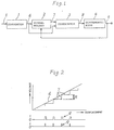
- Fig. 1 is a block diagram of a system of the first construction of the invention;
- Fig. 2 is a graph for explanation of the principle of the invention ;
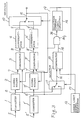
- Fig. 3 is a block diagram of a system of the second construction of the invention;
- Figs. 4(a) and 4(b) are graphs for explanation of the operation of the system of the second construction shown in Fig.3;
- Fig. 5 is a block diagram of a modified form of the system of the second construction of the invention;
- Fig. 6 is a block diagram of another modified form of the system of the second construction of the invention;
- Fig. 7 is a block diagram of a system of the third construction of the invention;
- Fig. 8 is a graph for explanation of the operation of the system of the third construction of the invention ;
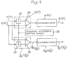
- Fig. 9 is a block diagram of two comparators having a single potential difference setting device in common;
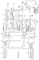
- Fig. 10 is a block diagram of a system of the fourth construction of the invention;
- Fig. 11 is a block diagram of a modified form of the system of the fourth construction of the invention;
- Fig. 12 is a block diagram of another modified form of the system of the fourth construction of the invention;
- Fig. 13 is a block diagram of a comparator used in the systems of the invention;
- Fig. 14 is a block diagram of an example of the sample and hold circuit used in the systems of the invention;
- Fig. 15 is a block diagram of another example of the sample and hold circuit;
- Fig. 16 is a graph for explanation of the circuit shown in Fig. 14;
- Fig. 17 is a graph for explanation of the circuit shown in Fig. 15; and
- Figs. 18 (a)(b)(c) and (d) schematically show the converters used in the systems of the invention.
- Referring to the drawings, first to Fig. 1, which shows a system of the first construction of the invention adapted for displacement in a single direction, there are shown a
converter 1, a sample and hold circuit (to be referred to as a signal holder or holder hereinafter ) 2,and a pulse producing means consisting of acomparator 3 and adifferentiator 4. Theconverter 1 can be a potentiometer of a known rotary type, which converts a physical quantity, i.e. anamount 5 of displacement to a corresponding voltage, which is produced as a first electrical signal (to be referred as a displacement signal) 6 to be applied to both thesignal holder 2 and thecomparator 3. - The sample and hold means or signal
holder 2 holds the level of the displacement signal 6 (to be referred to as the held value) at the time theoutput pulse 9 from thedifferentiator 4 is applied to theholder 2, and outputs a heldvalue signal 7 to be applied to thecomparator 3. - The
comparator 3 compares thedisplacement signal 6 from theconverter 1 with a reference signal, i.e. the heldvalue signal 7 from thesignal holder 2, and provides anoutput pulse signal 8 only when thedisplacement signal 6 has exceeded the heldvalue signal 7 by a predetermined voltage (to be referred to as the reference amount or value) R. - The
output pulse signal 8 from thecomparator 3 is applied to thedifferentiator 4, which produces anoutput pulse signal 9 to be applied to an outside pulse counter, not shown, and also to thesignal holder 2 as a timing signal to cause the level of thereference signal 7 then held by thesignal holder 2 to be replaced by the level of thedisplacement signal 6 being applied to thesignal holder 2 at that time. - The above operation of the system is graphically shown in Fig. 2. As the
displacement signal 6 from theconverter 1 increases to reach a level a predetermined voltage (the reference value) R, say, 1 millivolt higher than the heldvalue signal 7 of thesignal holder 2, thecomparator 3 produces anoutput pulse signal 8. In other words, theoutput signal 8 from thecomparator 3 becomes logic "1". Thedifferentiator 4 shapes the waveform of thesignal 8 and produces apulse signal 9. Thepulse signal 9 causes thesignal holder 2 to replace the voltage (the held value signal) 7 it has been holding until then by the input voltage (the displacement signal) 6 at that time. In other words, the input voltage at that time becomes a new reference signal or held value, respectively, of thesignal holder 2, whereupon the difference between the levels of thesignals signal 8 changes from logic "1" to "0". - As the
displacement signal 6 increases, the above operation is repeated with the result that thedifferentiator 4 produces a series ofpulses 9 the number of which corresponds to the amount of displacement. Thepulses 9 may be counted by a pulse counter, and the counted value may be indicated as an amount of displacement on an indicator. - In the system of Fig. 1, since a
single converter 1 is employed, the diameter of the resistor of a rotary type poteniometer or the length of the resistor of a linear type potentiometer sets a limit to the effective range of displacement. The range may be widened by employing a plurality of converters. A typical rotary type potentiometer has an effective measuring angular range of 250° to 350°. As shown in Fig. 18(a), two rotary type potentiometers r₁ and r₂ may be aligned on a common axis A and displaced angularly about 180° from each other, with their respective sliders S₁ and S₂ fixed on the common axis A at the same angular position. As shown in Fig. 18(b), two rotary type potentiometers r₁ and r₂ may also be aligned on a common axis A at the same angular position, with their resepctive sliders S₁ and S₂ fixed on the axis angularly displaced 180° from each other. It is further possible to arrange two rotary type potentiometers r₁ and r₂ side by side on a pair of parallel axes A₁ and A₂, with their sliders S₁ and S₂ fixed to the axes A₁ and A₂, respectively, 180° apart from each other, as shown in Fig. 18(c). A pair of gears G₁ and G₂ are fixed to the axes A₁ and A₂, respectively, with a pinion gear G meshing with the gears G₁ and G₂, so that rotation of the gear G causes simultaneous rotation of the gears G₁ and G₂. Fig. 18(d) shows a different embodiment in which a single circular resistor r is provided with a pair of sliders S₁ and S₂ fixed to an axis A concentric with the circle of the resistor and angularly displaced 180° from each other and electrically insulated from each other. - With the above-mentioned converters, since the outputs taken out of the sliders S₁ and S₂, that is, the displacement signals 6 and 6' from the
converters 1 and 1' have their phases displaced 180° from each other, as shown in Fig. 4a, it is possible to arrange so that before the output from one of the potentiometers r₁ and r₂ goes out of the effective range, the output from the other enters the range. If the circular resistors of the potentiometers have an effective angular range smaller than that above-mentioned, three or more potentiometers may be used to have a continuous range of 360°. - When linear type potentiometers are to be used, by arranging as many of them as are required in such a manner that the end portions of each adjacent two converting elements overlap each other and switching from one of the elements to a succeeding one, it is possible to continuously cover the whole distance of displacement to be measured.
- If linear motion is converted to rotary motion by suitable means such as gears, a rotary encoder may be used instead of a linear encoder to measure linear displacement.
- Fig. 3 shows a system of the second construction of the invention, in which two such converters as mentioned above are used. The system of Fig. 3 comprises a first and a second subsystems and a control circuit. The first subsystem comprises a
converter 1, asignal holder 2, acomparator 3 and adifferentiator 4. These circuit components and their input andoutput signals corresponding signals - The control circuit comprises a first and a
second selector limit signal generator 12, acomparator 13, an AND element AN₁ and a selectioncommand signal generator 14 in the form of a flip-flop. - The
selector 10 selects either one of theoutput signal 9 of thedifferentiator 4 of the first subsystem and the output signal 9' of the differentiator 4' of the second subsystem depending upon whether the output signal (that is, the selection command signal) 19 of theselection signal generator 14 is logic "1" or "0", and produces acorresponding output signal 15. In the system of Fig. 1, the held value of thesignal holder 2, that is, the level of thedisplacement signal 6 is renewed by theoutput signal 9 of thedifferentiator 4. In the system of Fig. 3, the held values of thesignal holders 2 and 2' of the first and second subsystems are renewed by theoutput 15 of theselector 10, that is, theoutput signal 9 or 9' of thedifferentiator 4 or 4'. - In the control circuit, the
selector 11 selects thedisplacement signal 6 or 6' of that one of the first and second subsystems which theselector 10 selects in accordance with theoutput signal 19 of the selectioncommand signal generator 14. The upperlimit signal generator 12 applies to thecomparator 13 an output signal (upper limit signal) 17 having a level corresponding to that of thedisplacement signal 6 or 6' which corresponds to a displacement a little before the effective operation range of theconverter 1 or 1' is exceeded (that is, to the upper limit of the effective operation range of theconverter 1 or 1'). - The
comparator 13 compares theoutput signal 16 from theselector 11 with theupper limit signal 17, and when thesignal 16 has reached the level of thesignal 17 as shown in Fig. 4b, thecomparator 13 applies an output signal(a logic "1" signal) 18 to one of the two inputs of the AND element AN₁ a predetermined value before the effective operation range of theconverter 1 or 1' is exceeded. - With the logic "1"
signal 18 being applied to one of the two inputs of the AND element AN₁, when the nextoutput pulse signal 15 of theselector 10 is applied to the other input of the AND element AN₁, it produces anoutput signal 36 to be applied to the selectioncommand signal generator 14, which recognizes that the upper limit of the effective operation range of the then operating subsystem, say, the first one (1 - 4) has been reached and reverses the logic state of itsoutput signal 19, whereupon theselectors output 15 of theselector 10. - In operation, as displacement increases, the first and second subsystems alternatively and alternately operate, so that the
signal 9 or 9' is produced as theoutput pulse signal 15. Since thesignal 9 or 9' is produced in the same manner as in the system of Fig. 1, no explanation will be given in this respect, but the operation of switching from the first to the second subsystem when the effective operation range of the first subsystem has been exceeded will be explained in further detail with reference to Figs. 3, 4a and 4b. Fig. 4b is an enlarged view of the encircled portion of Fig. 4a. - The
displacement signal 6 of the first subsystem selected by the selection command signal (a logic "0" signal) 19 from the selectioncommand signal generator 14 is applied as thesignal 16 to thecomparator 13 through theselector 11. When the level of theinput signal 16 has reached that of theupper limit signal 17 from the upperlimit signal generator 12, thecomparator 13 produces anoutput signal 18 indicating that the upper limit of the effective operation range of theconverter 1 has been reached, and applies thesignal 18 to one input of the AND element AN₁. As the displacement further increases, thedisplacement signal 6 increases until thenext pulse signal 9 is produced, whereupon theselector 10 which is now selecting the first subsystem (1 - 4) outputs thesignal 9 as thesignal 15 to be applied to the other input of the AND element AN₁. Now both inputs of the AND element AN₁ are "1", so that the AND element AN₁ produces anoutput 36, which causes the selectioncommand signal generator 14 to change its output from "0" to "1" thereby to switch theselectors - While the first subsystem was operating, the
output pulse signal 15 is applied to the signal holder 2' as well as thesignal holder 2 to renew the held value of the signal holder 2', so that the continuity of theoutput signal 15 is maintained despite the switching from one of the two subsystems to the other. - Fig. 5 shows a first modification of the system of Fig. 3. In the arrangement of Fig. 3 each of the first and second subsystems includes a
comparator 3, 3' and adifferentiator 4, 4'. In the arrangement of Fig. 5 aselector 10 is connected to the outputs of thesignal holders 2 and 2' for simplification of the circuit design with asingle comparator 3 and asingle differentiator 4 for both the first and second subsystems. The operation of the system of Fig. 5 will be easily understood from the above description of the system of Fig. 3, so that no explanation will be given. - Fig. 6 shows a second modification of the system of Fig. 3. In the system of Fig. 6 a
selector 11 is connected to the outputs of theconverters 1 and 1' for simplification of the circuit design with asingle signal holder 2, asingle comparator 3 and asingle differentiator 4 for the first and second subsystems. In the system of Fig. 6, theoutput 9 from thedifferentiatbr 4 is applied through adelay circuit 21 to thesignal holder 2 to renew the signal held by theholder 2. - In the systems of Figs. 3 and 5, the held values of the
holders 2 and 2' are renewed the instant the output 9 (15) is produced. In the system of Fig. 6, thedelay circuit 21 applies theoutut signal 9 from thedifferentiator 4 as a delayedsignal 20 to thesignal holder 2 for renewal of the held value thereof. This arrangement ensures that when theoutput signal 19 from the selectioncommand signal generator 14 causes theselector 11 to switch from one of theconverters 1 and 1' to the other, only after thedisplacement signal 6 or 6' from the newly selectedconverter 1 or 1' is applied to thesignal holder 2 to be held therein as a new held signal, thecomparator 3 compares the newly held level of thedisplacement signal 6 or 6' and the subsequent level thereof. If theoutput pulse 9 of thedifferentiator 4 were applied to thesignal holder 2 without passing through thedelay circuit 21 to renew the level of the displacement signal, say, 6 held by theholder 2 and then theselector 11 were switched to select the other converter, say, 1', the renewed signal held by theholder 2 would have the high level of thedisplacement signal 6 of theprevious converter 1 before the switching from theconverter 1 to the converter 1', so that the low level of the signal 6' of the newly selected converter 1' would be compared with the high level of thesignal 6 of theprevious converter 1. Under the condition, even when the displacement signal 6' changes by the reference value, the level of the signal 6' would not reach the high level of thesignal 6 now held by theholder 2, so that thedifferentiator 4 would not produce anoutput pulse 9. - In the system of Fig. 6, due to the
delay circuit 21 it takes a longer time to have the held signal level of theholder 2 renewed, with resulting reduction of the accuracy of production of a pulse train. The disadvantage, however, is offset by simplification of the whole circuit arrangement. - The above systems are adapted for increasing displacement. Fig. 7 shows a system of the invention adapted for displacements both increasing and decreasing. The system of Fig. 7 is a modification of the embodiment of Fig. 1 so arranged as to be able to operate both when displacement increases and when it decreases. In Fig. 7 the same reference numerals as in Fig. 1 designate corresponding components, which operate in the same manner as in Fig. 1, and those components which operate as displacement decreases and the signals then produced by the components are designated by the same reference numerals suffixed with a as those corresponding components which operate as displacement increases and the signals then produced by the components.
- In Fig. 7, in addition to the
comparator 3, anothercomparator 3a is provided to compare thedisplacement signal 6 from theconverter 1 with the heldvalue signal 7 from thesignal holder 2. When thedisplacement signal 6 has decreased by a predetermined voltage as compared with the heldvalue signal 7, or when the difference between thesignals comparator 3a produces anoutput signal 8a, which adifferentiator 4a receives to output apulse signal 9a. An OR element OR₁ has its two inputs connected to the outputs of thedifferentiators output signal output signal 23 to thesignal holder 2 to renew the held value. - The operation of the system of Fig. 7 will now be described with reference to Fig. 8 as well as Fig. 7. Regardless of whether displacement is increasing or decreasing, the
signal holder 2 holds the level of thedisplacement signal 6 which corresponds to the position D of displacement when theprevious pulse comparator displacement signal 6 which corresponds to a predetermined voltage difference (reference value) R, the comparator produces anoutput differentiator output pulse 9 or 9', which is applied to a pulse counter, not shown, as well as the OR element OR₁. - In order to provide the
comparators single device 26 for setting a potential difference (reference value) may be connected to bothcomparators - Fig. 10 shows a system of the fourth construction of the invention having the functions of the systems of Figs. 3 and 7. In particular, the system of Fig. 10 comprises two subsystems each of which is shown in Fig. 7 and operable in response to displacement in opposite directions, and means for enabling alternate operation of the two subsystems. When the
displacement signal 6 or 6' reaches its upper or lower limit, switching is conducted from that one of the two subsystems which has been operating until then to the other. - The signals from the corresponding components in the two subsystems are 180° out of phase from each other and are designated by the same reference numerals with and without a prime ('). Those output signals which are produced as displacement decreases are designated by the same reference numerals suffixed with a as those output signals which are produced as displacement increases. An AND element AN₂ equivalent to the AND element AN₁ receives the
output signal 15a from thedifferentiator 4a or 4'a and the output signal 18a or 18'a from the comparator 13a or 13'a through aselector 50 and applies its output to a selectioncommand signal generator 14 through an OR element OR₂. - The operation of the system of Fig. 10 is a combination of the operations of the systems shown in Figs. 3 and 7 and will be easily understood from the description of their respective operations, so that a simple description will suffice.
- The
selector 50 produces anoutput signal 15 as theamount 5 or 5' of displacement increases and anoutput signal 15a as the amount of displacement decreases. As displacement increases or decreases, theoutput signal 6 or 6' from theconverter 1 or 1' increases or decreases to the upper or lower limit level, whereupon the selectioncommand signal generator 14 produces aselection command signal 19 to cause theselector 50 to switch from the then operating one of the two subsystems to the other. - Fig. 11 shows a first modification of the system of Fig. 10. In Fig. 11, there is provided a
selector 11, through which theoutputs 6 and 6' of theconverters 1 and 1' are applied to thecomparators 13 and 13a, so that the comparators 13' and 13'a in Fig. 10 may be eliminated. Theselector 51 in Fig. 11 corresponds to thecomparator 50 in Fig. 10 except that theoutputs 18 and 18a of theselector 13 and 13a are applied directly to the AND elements AN₁ and AN₂, respectively, without passing through theselector 51. The operation of the system of Fig. 11 can be easily understood from the description of the system of Fig. 10, so that no explanation will be given. - Fig. 12 shows a second modification of the system of Fig. 10. In Fig. 12, the comparators 3', 3'a, 13' and 13'a, and the differentiators 4' and 4'a in Fig. 10 are eliminated, and the outputs (held value signals) 7 and 7' from the
signal holders 2 and 2' are applied to thecomparators selector 52, which includes the function of theselector 11 in Fig. 11. The operation of the system of Fig. 12 can also be easily understood, so that no explanation will be given. - In the previous embodiments, the interval between output pulses 9 (9a, 9', 9'a), that is, the amount of displacement (or the reference value R) that occurs from the time at which the previous pulse was produced to the time at which the present pulse has been produced is set to a predetermined value, so that the systems have a fixed pulse density or resolution. By making the above-mentioned interval variable it is possible to have a variable pulse density. To this end, each of the
comparators comparator 24, anadder 25 and adevice 26 for setting a potential difference (the reference value R), as shown in Figs. 9 and 13. - In the system where the comaprators 3 (3') and 3a (3'a) are provided for displacement in both increasing and decreasing directions, a common reference
value setting device 26 is provided for both the comparators 3 (3') and 3a (3'a), as shown in Fig. 9 in order that there may not be a difference in sensitivity between displacement in increasing and decreasing directions. In either case, in order to make the sensitivity variable, thedevice 26 must have its output voltage variable. - Various types of variable reference value setting devices may be used, such as a potentiometer in which the set reference value or potential difference is varied manually or in response to changes of exterior conditions, or a device in which a desired potential difference can be set with a D/A converter controlled by an exterior electronic device or computer.
- In the above arrangements, the
signal holders 2 and 2' have the function of accurately maintaining the level of the voltage corresponding to the displacement when the previous output pulse 9 (9', 9a, 9a', 15 or 15a) was produced until the next pulse is produced. In this type of encoder, an unintended displacement sometimes occurs, and it is desirable that the instrument remains insensitive to such unintended displacements. Such displacements to which the instrument should remain insensitive occurs usually at a low speed. - In accordance with the invention, it is possible to make the instrument insensitive to displacements occurring at a low speed by using as each of the
signal holders 2 and 2' a sample and hold circuit (to be referred to as the S/H circuit hereinafter) composed of acapacitor 32,operational amplifiers switching circuit 31, as shown in Fig. 14. The switchingcircuit 31 usually is an electronic circuit. So long as there is no renewal command signal 9 (15, 20, 23) applied to the signal holder 2 (2'), theswitch 31 remains open, so that the terminal voltage of thecapacitor 32 is taken out through theoperational amplifier 34 as an output signal 7 (7') . When the signal 9 (15, 20, 23) is applied to theswitch 31, theswitch 31 is closed, so that the input displacement signal 6 (6') from the converter 1 (1') is applied to thecapacitor 32 through theoperational amplifier 33 and theclosed switch 31 to charge thecapacitor 32, whereupon the level of the displacement signal 6 (6') is held by the holder 2 (2') and the terminal voltage of thecapacitor 32 becomes the output held value signal 7 (7') of the holder 2 (2'). The operation, which is called sampling, is graphically shown in Fig. 16. The renewal command signal 9 (15, 20, 23), which is the output from the differentiator 4 (4a', 4', 4'a), has a pulse width so negligibly small as compared with the interval between theoutput pulses 9, so that the sampling operation is completed instantly and does not affect the operation of the whole system. - In the S/H circuit of Fig. 14, the
switch 31 is either completely open or completely closed. - Fig. 16 graphycally shows the relation between the speed of displacement or the change of the displacement signal 6 (6') and the held value signal 7 (7') of the signal holder 2 (2'). Each time the difference between the signal 6 (6') which is increasing and the signal 7 (7') reaches the reference value R, an
output pulse 9 is produced. As the speed of displacement, that is, the inclination of the curve 6 (6') in Fig. 16 decreases, the interval between thepulses 9 increases. - In order to make the system insensitive to displacements occurring at a low speed, a resistor 35 is connected across the
switch 31 of the S/H circuit constituting the signal holder 2 (2'), as shown in Fig. 15, thereby to keep theswitch 31 conducting even while it is open. The instant theswitch 31 is closed, the displacement signal 6 (6') charges thecapacitor 32 to the level of the input voltage (so that the held value of the signal holder 2 (2') is renewed) in a moment as in the arrangement of Fig. 14. Even while theswitch 31 is open, thecapacitor 32 is gradually charged through the resistor 35, so that the terminal voltage or signal 7 (7') increases as shown by the curve inclining upwardly toward the right in Fig. 17. - Suppose that the speed of the displacement to which the system should be kept insensitive is preset to, for example, a speed that one
pulse 9 is produced in every two (2) seconds by the capacitance of thecapacitor 32 and the resistance of the resistor 35. The speed of displacement will be referred to as the displacement insensitive speed hereinafter. Suppose that a displacement occurs at such a speed that ten (10)pulses 9 are produced in every one second. The system operates noramlly, that is, the output held value signal 7 (7') from the signal holder 2 (2') gradually changes with the input displacement signal 6 (6'). Since the change of the signal 6 (6') is greater than that of the signal 7 (7') , the difference between the levels of the two signals presently reaches the reference value R, whereupon an output pulse 8 (9) is produced. The condition continues until a pulse Pn is produced as shown in Fig. 17. - Suppose that the displacement is slowed down to a speed such that one
pulse 9 is produced in every five (5) seconds. Even when there has occurred a displacement from the position where the output pulse Pn was produced to a position where the next output pulse is expected to be produced, since the change (or increase) of the input displacement signal 6 (6') is accompanied by charging of thecapacitor 32 through the resistor 35 at the same speed as the change of the input signal, the terminal voltage of thecapacitor 32, that is, the held value signal 7 (7') of the signal holder 2 (2') with which the input displacement signal 6 (6') is to be compared changes (or increases) so as to approach the level of the input signal 6 (6') as shown at the right side of the pulse Pn in Fig. 17, and the comparator 3 (3') will not produce anoutput signal 8. In other words, the system remains insensitive to any displacement occurring at a low speed. - There are various changes and modifications other than the arrangements above described. For example, in the system of Fig. 10 one of the
signal holders 2 an 2' may be eliminated as in the system of Fig. 6 with necessary changes to the circuitry. - In the arrangements of Figs. 5, 6, 10, 11 and 12, two subsystems are operated alternately. Three or more subsystems may also be used.
- In the illustrated embodiments the physical quantity treated by the systems is position. It is possible to treat with any other physical qunatities.
- In accordance with the invention, it is possible to continuously change the pulse density or resolution of the system and set it to a value suitable for a particular application.
- It is only upon occurrence of a displacement from the position where the previous output pulse was produced to a position where the next pulse is to be produced that an output pulse is produced, so that no chattering will occur.
- In the conventional rotary encoder having a circular plate on which graduation marks are printed or otherwise formed fixedly, mechanical precision and accuracy are required. The invention does not require any such circular plate or graduations. Nor does it require mechanical precision or accuracy, so that the instrument of the invention is simple and easy to manufacture, and there will be no errors caused by abraision of mechanical parts due to long or frequent use.
- The apparatus of the invention can be used as a device for initially teaching movements and positions to a robot or graphical processing for inputting information about position into a computer, such as a CAD system, a mouse, a touch ball, etc. The invention can be applied to a dial for setting values in various measuring instruments, controllers, communication devices, etc. Method and apparatus for producing pulses in accordance with the change of a physical quantity, wherein each time an electric pulse is produced, the value of the physical quantity is sampled and held; and each time the physical quantity has changed by a prdetermined reference amount with respect to the sampled and held value thereof, one output electric pulse is produced to cause the sampled and held value to be replaced by the value of the physical quantity at that time; and the above operations are repeated to produce a series of output pulses whose number corresponds to the amount of change of the physical quantity. By counting the number of the output pulses it is possible to know the amount of change, and by changing the reference amount it is possible to change the interval or density of the output pulses thereby to change the resolution.
Claims (7)
- A method of producing electrical pulses in accordance with the change of a physical quantity (5) comprising the steps of converting said physical quantity (5) into a corresponding first electrical signal (6), and
comparing said first electrical signal (6) and a reference signal (7) and producing an output pulse (9) only if the difference between said first electrical signal (6) and said reference signal (7) is larger than a predetermined reference amount (R),
characterised by the step of
generating said reference signal (7) by sampling and holding the value of said first electrical signal (6) each time said output pulse (9) is produced. - The method of claim 1,
characterised in that
said reference amount (R) is variable so that the density of said output pulses (9) produced is made variable. - An apparatus for producing electrical pulses, comprising a converter means (1) for converting a physical quantity (5) into a corresponding first electrical signal (6), and a pulse producing means (3, 4) for comparing said first electrical signal (6) and
a reference signal (7) and producing an output pulse (9) only if the difference between said first electrical signal (6) and said reference signal (7) is larger than a predetermined reference amount (R),
characterised by
sample and hold means (2) for sampling and holding the value of said first electrical signal (6) each time said output pulse (9) is produced and thereby generating said reference signal (7). - The apparatus according to claim 3,
characterised in that
said converter means comprises a plurality of converters (1, 1') operable in response to the same physical quantity (5, 5') in different, continuous measuring ranges to convert said physical quantity (5, 5') to a corresponding first electrical signal (6, 6'); and further including comparing means (13) for comparing said first electrical signal (6, 6') from each of said converters (1, 1') with a predetermined limit value (17), and selecting means (10, 11, 14, AN1) for switching from that one of said converters (1, 1') whose first electrical signal (6, 6') has reached said limit value (17) to the next one of said converters (1, 1') whose first electrical signal (6, 6') has not yet reached said limit value (17) so as to select said output pulse (9, 9') from said pulse producing means (3, 3', 4, 4') caused by said output pulse (9, 9') from said next one of said converters (1, 1'). - The apparatus according to claim 3 or 4,
characterised in that
said pulse producing means (3, 4) is so constructed as to produce one output pulse (9) each time the difference between said reference value (7) of said first electrical signal (6) in said sample and hold means (2) and said first electrical signal (6) changing in both increasing and decreasing directions has reached said reference amount (R). - The apparatus according to claim 3, 4 or 5,
characterised in that
said predetermined reference amount (R) is variable. - The apparatus according to claim 3, 4, 5 or 6,
characterised in that
said sample and hold means (2, 2') includes means (35) for changing said reference value (7) of said first electrical signal (6, 6') from said converter means (1, 1') to approach said first electrical signal (6, 6') applied thereto when the speed of change of said first electrical signal (6, 6') is below a predetermined value.
Priority Applications (3)
| Application Number | Priority Date | Filing Date | Title |
|---|---|---|---|
| US07/767,822 US5434564A (en) | 1991-09-30 | 1991-09-30 | Method and apparatus for producing pulses corresponding in number to the amount of changes in a physicial quantity |
| EP91117210A EP0540763B1 (en) | 1991-09-30 | 1991-10-09 | Method and apparatus for producing pulses |
| DE1991616367 DE69116367T2 (en) | 1991-10-09 | 1991-10-09 | Method and device for generating pulses |
Applications Claiming Priority (2)
| Application Number | Priority Date | Filing Date | Title |
|---|---|---|---|
| US07/767,822 US5434564A (en) | 1991-09-30 | 1991-09-30 | Method and apparatus for producing pulses corresponding in number to the amount of changes in a physicial quantity |
| EP91117210A EP0540763B1 (en) | 1991-09-30 | 1991-10-09 | Method and apparatus for producing pulses |
Publications (2)
| Publication Number | Publication Date |
|---|---|
| EP0540763A1 EP0540763A1 (en) | 1993-05-12 |
| EP0540763B1 true EP0540763B1 (en) | 1996-01-10 |
Family
ID=26129039
Family Applications (1)
| Application Number | Title | Priority Date | Filing Date |
|---|---|---|---|
| EP91117210A Expired - Lifetime EP0540763B1 (en) | 1991-09-30 | 1991-10-09 | Method and apparatus for producing pulses |
Country Status (2)
| Country | Link |
|---|---|
| US (1) | US5434564A (en) |
| EP (1) | EP0540763B1 (en) |
Families Citing this family (6)
| Publication number | Priority date | Publication date | Assignee | Title |
|---|---|---|---|---|
| JPH05291891A (en) * | 1992-02-14 | 1993-11-05 | Ricoh Co Ltd | Primary random pulse train generating circuit device |
| US5703506A (en) * | 1995-12-26 | 1997-12-30 | Motorola | Signal processing method |
| US5836982A (en) * | 1997-02-19 | 1998-11-17 | Medtronic, Inc. | System and method of data compression and non-linear sampling for implantable and battery-powered devices |
| GB9827932D0 (en) * | 1998-12-19 | 1999-02-10 | Secr Defence | Analogue to digital converter and method of analogue to digital conversion |
| DE19937155A1 (en) * | 1999-08-06 | 2001-03-15 | Bosch Gmbh Robert | System for generating a signal for superimposing information |
| DE10042007A1 (en) * | 2000-08-26 | 2002-03-07 | Bosch Gmbh Robert | Device and method for measuring angles |
Family Cites Families (11)
| Publication number | Priority date | Publication date | Assignee | Title |
|---|---|---|---|---|
| US3753133A (en) * | 1972-04-05 | 1973-08-14 | Bell Telephone Labor Inc | Trigger circuit for recording and transmitting sampled analog waveforms |
| JPS5642488B2 (en) * | 1974-08-02 | 1981-10-05 | ||
| SE407636B (en) * | 1976-07-30 | 1979-04-02 | Svensk Vaermemaetning | DEVICE FOR REGISTERING QUANTITIES, CORRESPONDING VOLUMES OR ENERGY AMOUNTS IN A CENTRAL MEDIUM COUNTING DEVICE |
| JPS583279B2 (en) * | 1976-09-18 | 1983-01-20 | 株式会社リコー | Pulse transmission/reception method |
| US4393371A (en) * | 1979-06-05 | 1983-07-12 | Morgan-Smith Electronics Ltd. | Analogue to digital signal conversion and storage system |
| US4297680A (en) * | 1979-08-03 | 1981-10-27 | John Fluke Mfg. Co., Inc. | Analog waveform digitizer |
| JPS6037660B2 (en) * | 1980-05-06 | 1985-08-27 | 日本ビクター株式会社 | Approximate compression method for audio signals |
| US4390844A (en) * | 1980-12-24 | 1983-06-28 | California Institute Of Technology | Integration filter for step waveforms |
| US4363976A (en) * | 1981-01-19 | 1982-12-14 | Rockwell International Corporation | Subinterval sampler |
| US4631540A (en) * | 1985-06-03 | 1986-12-23 | Sperry Corporation | Angular position to linear voltage converter |
| JPS63205507A (en) * | 1987-02-21 | 1988-08-25 | Fanuc Ltd | Detection system for absolute position |
-
1991
- 1991-09-30 US US07/767,822 patent/US5434564A/en not_active Expired - Lifetime
- 1991-10-09 EP EP91117210A patent/EP0540763B1/en not_active Expired - Lifetime
Also Published As
| Publication number | Publication date |
|---|---|
| US5434564A (en) | 1995-07-18 |
| EP0540763A1 (en) | 1993-05-12 |
Similar Documents
| Publication | Publication Date | Title |
|---|---|---|
| GB2233459A (en) | Linearising and calibrating surface characteristic measuring apparatus | |
| US20100222967A1 (en) | Multiturn rotational sensor | |
| EP0540763B1 (en) | Method and apparatus for producing pulses | |
| EP1943482B1 (en) | Method for signal processing of capacitive measurement scales | |
| JPS614919A (en) | Position encoder compensator | |
| EP2131156A1 (en) | Phase detection device and position detection device | |
| JPH04279817A (en) | Absolute encoder | |
| US20020121992A1 (en) | Calibrated encoder multiplier | |
| EP0199826B1 (en) | Method of detecting position | |
| JP3074484B2 (en) | Pulse generating method and apparatus | |
| CN111368584A (en) | Self-correcting high-resolution position information splicing method for sine and cosine encoder | |
| US6934641B2 (en) | Motion detection and analysis | |
| EP0262881B1 (en) | Apparatus for indicating the value of a variable | |
| JP3104090B2 (en) | Timing signal generation method and apparatus | |
| EP0200791A1 (en) | Method and apparatus for detecting position | |
| EP1103790A2 (en) | Motion detection and analysis | |
| RU2727345C1 (en) | Hybrid angular position measurement sensor | |
| JPH04297817A (en) | Absolute encoder | |
| JPH0629723B2 (en) | Absolute position measuring method and device | |
| JPS6057011B2 (en) | Internal massage device in displacement measuring device | |
| JP3077095B2 (en) | Digital converter for position detection | |
| JPS6365316A (en) | Optical displacement detecting device | |
| JPH0412816B2 (en) | ||
| JPS6197520A (en) | Displacement detector | |
| SU439758A1 (en) | Profile indicator |
Legal Events
| Date | Code | Title | Description |
|---|---|---|---|
| PUAI | Public reference made under article 153(3) epc to a published international application that has entered the european phase |
Free format text: ORIGINAL CODE: 0009012 |
|
| AK | Designated contracting states |
Kind code of ref document: A1 Designated state(s): DE FR GB IT NL |
|
| 17P | Request for examination filed |
Effective date: 19931001 |
|
| 17Q | First examination report despatched |
Effective date: 19940912 |
|
| GRAA | (expected) grant |
Free format text: ORIGINAL CODE: 0009210 |
|
| AK | Designated contracting states |
Kind code of ref document: B1 Designated state(s): DE FR GB IT NL |
|
| REF | Corresponds to: |
Ref document number: 69116367 Country of ref document: DE Date of ref document: 19960222 |
|
| ITF | It: translation for a ep patent filed |
Owner name: SAIC BREVETTI S.R.L. |
|
| ET | Fr: translation filed | ||
| PLBE | No opposition filed within time limit |
Free format text: ORIGINAL CODE: 0009261 |
|
| STAA | Information on the status of an ep patent application or granted ep patent |
Free format text: STATUS: NO OPPOSITION FILED WITHIN TIME LIMIT |
|
| 26N | No opposition filed | ||
| REG | Reference to a national code |
Ref country code: GB Ref legal event code: IF02 |
|
| PGFP | Annual fee paid to national office [announced via postgrant information from national office to epo] |
Ref country code: DE Payment date: 20091029 Year of fee payment: 19 |
|
| PGFP | Annual fee paid to national office [announced via postgrant information from national office to epo] |
Ref country code: NL Payment date: 20091027 Year of fee payment: 19 |
|
| PGFP | Annual fee paid to national office [announced via postgrant information from national office to epo] |
Ref country code: IT Payment date: 20091023 Year of fee payment: 19 Ref country code: FR Payment date: 20091110 Year of fee payment: 19 Ref country code: GB Payment date: 20091023 Year of fee payment: 19 |
|
| REG | Reference to a national code |
Ref country code: NL Ref legal event code: V1 Effective date: 20110501 |
|
| GBPC | Gb: european patent ceased through non-payment of renewal fee |
Effective date: 20101009 |
|
| PG25 | Lapsed in a contracting state [announced via postgrant information from national office to epo] |
Ref country code: FR Free format text: LAPSE BECAUSE OF NON-PAYMENT OF DUE FEES Effective date: 20101102 |
|
| REG | Reference to a national code |
Ref country code: FR Ref legal event code: ST Effective date: 20110630 |
|
| PG25 | Lapsed in a contracting state [announced via postgrant information from national office to epo] |
Ref country code: GB Free format text: LAPSE BECAUSE OF NON-PAYMENT OF DUE FEES Effective date: 20101009 Ref country code: NL Free format text: LAPSE BECAUSE OF NON-PAYMENT OF DUE FEES Effective date: 20110501 |
|
| REG | Reference to a national code |
Ref country code: DE Ref legal event code: R119 Ref document number: 69116367 Country of ref document: DE Effective date: 20110502 |
|
| PG25 | Lapsed in a contracting state [announced via postgrant information from national office to epo] |
Ref country code: IT Free format text: LAPSE BECAUSE OF NON-PAYMENT OF DUE FEES Effective date: 20101009 |
|
| PG25 | Lapsed in a contracting state [announced via postgrant information from national office to epo] |
Ref country code: DE Free format text: LAPSE BECAUSE OF NON-PAYMENT OF DUE FEES Effective date: 20110502 |