EP0540419B1 - Frame for mounting devices for non-contact high-temperature inspection of moulded articles, particularly of glass - Google Patents
Frame for mounting devices for non-contact high-temperature inspection of moulded articles, particularly of glass Download PDFInfo
- Publication number
- EP0540419B1 EP0540419B1 EP92402934A EP92402934A EP0540419B1 EP 0540419 B1 EP0540419 B1 EP 0540419B1 EP 92402934 A EP92402934 A EP 92402934A EP 92402934 A EP92402934 A EP 92402934A EP 0540419 B1 EP0540419 B1 EP 0540419B1
- Authority
- EP
- European Patent Office
- Prior art keywords
- conveyor belt
- photodiodes
- light
- frame
- framework
- Prior art date
- Legal status (The legal status is an assumption and is not a legal conclusion. Google has not performed a legal analysis and makes no representation as to the accuracy of the status listed.)
- Expired - Lifetime
Links
Images


Classifications
-
- G—PHYSICS
- G01—MEASURING; TESTING
- G01N—INVESTIGATING OR ANALYSING MATERIALS BY DETERMINING THEIR CHEMICAL OR PHYSICAL PROPERTIES
- G01N21/00—Investigating or analysing materials by the use of optical means, i.e. using sub-millimetre waves, infrared, visible or ultraviolet light
- G01N21/84—Systems specially adapted for particular applications
- G01N21/88—Investigating the presence of flaws or contamination
- G01N21/90—Investigating the presence of flaws or contamination in a container or its contents
-
- G—PHYSICS
- G01—MEASURING; TESTING
- G01N—INVESTIGATING OR ANALYSING MATERIALS BY DETERMINING THEIR CHEMICAL OR PHYSICAL PROPERTIES
- G01N21/00—Investigating or analysing materials by the use of optical means, i.e. using sub-millimetre waves, infrared, visible or ultraviolet light
- G01N21/84—Systems specially adapted for particular applications
- G01N2021/845—Objects on a conveyor
-
- G—PHYSICS
- G01—MEASURING; TESTING
- G01N—INVESTIGATING OR ANALYSING MATERIALS BY DETERMINING THEIR CHEMICAL OR PHYSICAL PROPERTIES
- G01N21/00—Investigating or analysing materials by the use of optical means, i.e. using sub-millimetre waves, infrared, visible or ultraviolet light
- G01N21/84—Systems specially adapted for particular applications
- G01N21/88—Investigating the presence of flaws or contamination
- G01N21/90—Investigating the presence of flaws or contamination in a container or its contents
- G01N2021/9063—Hot-end container inspection
Definitions
- the present invention relates to a chassis, allowing the mounting of various contactless control devices, for molded objects, in particular high temperature glass objects such as bottles, produced at high speed automatically.
- the molding machines usually used comprise a conveyor belt driven continuously on which the molded objects, such as glass bottles, are deposited by the action of a clamp which comes to take the bottle in the mold, the bottle then being pushed on the conveyor by means of a pivoting push rod.
- the level of the gripper of the molded bottle is constant with respect to the soil on which the molding machine is installed.
- the machine is generally capable of manufacturing bottles of variable size so that it is necessary at the time of a change of manufacture to modify the level of the conveyor belt relative to the ground at the location of the molding machine.
- the bottles transported on the conveyor are subjected to different treatments, before being brought into an oven called "annealing arch" inside which the glass bottles are subjected to a heat treatment final annealing.
- the object of the present invention is to solve these difficulties and to allow a reliable and precise installation of a set of control devices for the implementation of an automatic contactless control method of molded objects, in particular glass bottles. , at high temperature.
- the mounting frame for non-contact control devices allowing the control of molded objects, in particular glass, at high temperature and in particular of bottles placed on a conveyor belt driven relative to an adjustable tilt frame in a vertical plane, includes two parallel reference planes interconnected by rigid columns so as to define a non-deformable structure spanning the conveyor belt in the manner of a bridge.
- the non-deformable structure is not linked to the conveyor frame but is supported by means of three jacks with controlled displacements.
- At least one device comprising a light source emitting a light beam whose characteristics depend on the inclination of the conveyor belt, cooperates with a network of photodiodes capable of emitting an electrical signal for controlling the jacks supporting the non-deformable structure in order to maintain permanently the reference planes of the chassis, strictly parallel to the plane of the conveyor belt regardless of the inclination thereof.
- the three jacks each comprise a rod movable in translation, preferably connected via a block of elastic material to a base for supporting the chassis.
- Each support base is embedded by its upper end in an appropriate housing of the chassis.
- the upper end of the support legs and the corresponding housings are of frustoconical shape.
- two rectilinear light sources are arranged strictly perpendicular to the reference planes and spaced from one another.
- the two sources each emit a brush of white light which is partially obscured by the frame of the conveyor belt.
- Two linear arrays of photodiodes cooperate with the two light sources.
- the photodiodes arrays are placed at the focal point of an optical focusing device, arranged so as to receive the two partially obscured light brushes.
- Means are further provided for determining at any time the number of photodiodes lit in each strip and for transmitting control signals from the cylinders in order to maintain the reference plane strictly parallel to the plane of the conveyor belt. Thanks to these two light sources, it is also possible to determine at any time the elevation of the conveyor belt relative to the reference planes of the chassis.
- a light emitter such as a laser, is moreover fixed integrally to the conveyor frame so as to emit a fine light beam strictly perpendicular to the plane of the conveyor belt.
- This transmitter cooperates with an optical system, preferably of the anamorphic type, secured to the chassis, and capable of transforming the fine light beam into a plane light brush substantially parallel to the vertical plane in which the inclination of the frame is adjustable.
- a linear array of photodiodes is arranged perpendicular to the trace of this light brush. Means are provided in order to determine at any time the diode or diodes of said strip lit by said light brush and to emit a control signal from the jacks in order to maintain the reference plane parallel to the plane of the conveyor belt.
- the exemplary embodiment illustrated in the drawings relates to the contactless control of glass bottles directly at the outlet of high temperature molding. It will of course be understood that the invention can also be applied to the control of other molded objects in so far as the same type of problem arises and in particular to molded plastic objects.
- the installation comprises a molding machine 1 comprising several independent sections for molding glass bottles.
- the bottles the size of which can vary for example between a small bottle 2a and a large bottle 2b, are moved at the outlet of the molding machine 1, on a conveyor belt 3 of which only the upper strand has been shown to simplify the figure .
- the bottles are extracted after molding by means of pliers 4 or "take out" whose axis is at a constant level with respect to the ground 5 on which the machine 1 is installed.
- FIG. 2 which illustrates on a larger scale the extraction of a molded bottle 2, we see that it is gripped by the clamp 4 which extracts it from the mold not shown in Figure 2, by a pivoting movement in a horizontal plane.
- the bottle 2 held by its neck at its upper part is placed above a perforated plate 6 located at the upper part of a box 7 subjected to a current of cold air.
- the cold air exits through the holes 6 and causes cooling or "racatorium" of the bottle 2 which has just left the mold of the manufacturing machine.
- this cooling is complete, that is to say after a period of time of a few fractions of a second, the clamp 4 deposits the bottle 2 on the plate 6, the new position of the bottle 2 being illustrated in FIG. 2 in dashes.
- a rotary push rod 8 pivots and acts on the bottle 2 so as to move it according to arrow 9 as far as the conveyor belt 3 by communicating to it further in this movement a speed substantially identical to the speed of movement of the conveyor 3.
- the constant height H of the axis of the clamp 4 relative to the ground 5 is also shown. and the variable height h of the upper surface of the conveyor 3 relative to the axis of the clamp 4 as a function of the size of the bottles 2.
- the conveyor belt 3 can therefore move in front of the molding machine 1 from a low position illustrated in solid lines to a high position illustrated in broken lines.
- the conveyor belt 3 can of course adopt other intermediate positions depending on the size of the desired bottles.
- the bottles 2 transported by the conveyor 3 pass, at the outlet of the manufacturing machine 1, a heat treatment hood 10 which allows for example the deposition of a thin layer of tin tetrachloride for example in order to seal the microcracks of the bottles that have just been manufactured.
- the conveyor 3 passes over a roller 11 movable vertically according to the position of the conveyor belt.
- the conveyor belt 3 passes over a second fixed roller 12 then in front of an oven 13 known as an "annealing arch" in which a plurality of bottles are introduced in rows perpendicular to the path of the conveyor belt 3 while being pushed to inside the annealing arch 13 by a thrust member not shown in FIG. 1.
- the belt of the annealing arch 13 being at a constant level, the conveyor belt 3 must also remain at a constant level in front of the annealing arch 13. As a result, the conveyor belt 3 must have an adjustable inclination between the rollers 11 and 12. However, it is precisely at this point that it is preferable to carry out the various hot controls on the bottles 2 immediately produced.
- FIG. 1 the schematic illustration of the chassis of assembly 14 of the present invention, mounted on the ground 5 by means of jacks 15 only two of which are illustrated diagrammatically in FIG. 1.
- the jacks 15 comprise rods 16 which can move vertically and which are connected to the support legs 17 of the chassis 14 by means of blocks 18 of elastic material, for example rubber or neoprene, capable of absorbing the shearing forces.
- the invention makes it possible to maintain the same inclination for the mounting frame 14 as for the conveyor belt 3 in the hot control zone for the bottles, the mounting frame 14 being able to occupy a first position illustrated in solid lines for the bottles 2b of large dimensions and a second position shown in broken lines for bottles 2a of small dimensions. Thanks to the modification of the inclination of the chassis 14, the various control devices which can be mounted on the chassis 14 always remain in a constant position relative to the conveyor belt 3, that is to say relative to the bottles 2 to be controlled. .
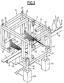
- FIG. 3 illustrates the general structure of the mounting frame 14.
- the mounting frame 14 is formed in the form of a non-deformable structure which spans the conveyor belt 3 and its fixed frame 19 in the manner of a bridge.
- the non-deformable structure of the chassis 14 comprises, in the illustrated example, two lower plates 20, 21 located in the same plane, defining a lower reference plane for the mounting chassis 14.
- the lower plane is located slightly below the plane of the conveyor belt 3 which moves longitudinally between the two plates 20, 21.
- Eight rigid and non-deformable columns referenced 22 are mounted respectively at the four corners of the two plates 20, 21 and connected to a horizontal upper frame constituted by four bars 23 also rigid and undeformable.
- the bars 23, 24 define a second upper reference plane for the mounting frame 14, the upper reference plane being perfectly parallel to the lower reference plane.
- All of the columns 22, 23, 24 like the plates 20, 21 are made of a solid material having a coefficient of thermal expansion close to zero so as to produce a rigid structure that is mechanically non-deformable whatever the temperature of objects such as glass bottles 2 which pass through the frame 14 while being moved on the conveyor belt 3.
- the mounting frame 14 is supported relative to the ground by three cylinders 15a, 15b and 15c, the two cylinders 15a, 15b supporting the plate 21 while the third cylinder 15c supports, substantially in its median zone, the plate 20.
- the three cylinders 15a, 15b and 15c are preferably mechanical-electric self-locking cylinders in the absence of electric current.
- the rods 16 of the three cylinders are guided and can move vertically without play.
- At the end of the rods 16 are blocks of elastic material 18 by means of which the rods 16 are connected to the legs 17 of which only one of the 'between them has been shown in Figure 3, the other legs being identical.
- the ends 17a of the support legs 17 are of frustoconical shape and are fitted into corresponding housings, also of frustoconical shape, formed in the thickness of the plates 21 and 20. Under these conditions, the legs 17 are rigidly connected by embedding at plates 20 and 21, the take-up of the inclination and of the shearing forces, being effected only by the elastic joints 18.
- the mounting frame 14 can then be easily reinstalled in position by simple descent above the three legs 17.
- the control of the inclination of the mounting frame 14 to that of the conveyor belt 3 is achieved in the example illustrated by means of three separate devices.
- the first two which are identical each consist of a rectilinear light source 26 mounted on the lower plate 20 perpendicular to the plane of the latter, that is to say perpendicular to the lower reference plane.
- the two light sources 26 are spaced from one another by being arranged in the vicinity of the two extreme edges of the plate 20 so as to direct a vertical brush 28 of white light towards the conveyor belt 3 and its fixed frame 19.
- two opto-electronic devices 27 mounted on the plate 21 so as to receive the light brush from the light sources 26 after partial obscuration by the frame 19 and the conveyor 3 and after suitable focusing.
- the light sources 26 are formed so that the light brushes 28 emitted, are partially obscured, preferably substantially half , by the conveyor belt 3 and its fixed frame 19.
- the third device is constituted for example by a laser transmitter 29, integral with the support 19 of the conveyor 3, and fixed on the frame 19 so as to emit a fine light beam 30 strictly perpendicular to the plane of the conveyor belt 3.
- An opto-electronic device 31 is fixed to the upper frame constituted by the horizontal bars 23, in a position such that it can receive the laser beam 30.
- the three opto-electronic devices 27 and 31 are capable of emitting an electrical signal for the control of the various jacks 15a, 15b and 15c in order to permanently maintain the reference planes lower and upper strictly parallel to the plane of the conveyor belt 3 and this whatever its inclination.
- the light ramp 26 is made up by a fluorescent tube, the longitudinal axis of which is perfectly perpendicular to the lower reference plane constituted by the plate 20 visible in FIG. 3.
- the fluorescent tube 26 is supplied with electric current by the connections 32, 33 connected to a high frequency converter 34.
- the converter 34 supplies the fluorescent tube 26 with high frequency current, for example of the order of 25 kHz in order to use the persistence of the light discharge in the tube 26 to obtain a continuous emission of light, ie without scintillations.
- the fluorescent tube 26 advantageously comprises a cover 35, defining a slot which lets through a thin vertical light brush 28, directed perpendicular to the conveyor belt 3 and towards it so as to be partially obscured by the fixed frame 19 which constitutes an obstacle opaque for the light brush 28.
- a conventional focusing optics 37 which directs the partially obscured light brush on a linear array of photodiodes 38 placed at the focus of the optics 37, and comprising a plurality of photodiodes 39, for example N photodiodes.
- the light beam 28 partially obscured by the frame 19 becomes a partial brush 40 when it reaches the array of photodiodes 38 thus illuminating a certain number of photodiodes 39 while others are not illuminated.
- the photodiode array 38 is connected by the connection 41 to a microprocessor 42 capable of emitting by the output connection 43 a signal used for controlling the jacks 15a, 15b and 15c.
- the detection of the exact position of the transition point on the array of photodiodes 38, is illustrated in FIG. 6, for an array of photodiodes 39 of even number.
- the photodiodes 39 are identified by a number which goes from 1 to N, the axis O of the array of photodiodes being between the diode N / 2 and the diode N / 2 + 1.
- the light amplitude as a function of the number of the diodes is represented on the upper graph of FIG. 6 which shows that part of the diodes 39, in the example illustrated, the diodes of number 1 to N / 2 are completely illuminated by the light brush 40 ( Figure 4).
- the servo is preferably designed so that the set value for the control signals of the cylinders 15a, 15b, 15c places the transition substantially at the center O of the array of photodiodes 38 and this for the two arrays of photodiodes 38, so to maintain the inclination of the mounting frame identical to that of the conveyor belt 3, that is to say to maintain the reference planes strictly parallel to the plane of the conveyor belt 3.
- the position of the transition points on the networks of photodiodes 38 makes it possible to measure at any time the elevation of the conveyor belt 3 relative to the reference plane constituted by the plates 20, 21.
- means are provided for stopping the transfer of the measurement signals when an object being on the conveyor obscures the light beam.
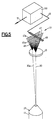
- FIG. 5 illustrates in an enlarged manner the optoelectronic device 31 cooperating with the laser beam 30.
- the protective cover 44 of the laser transmitter 29 which emits the laser beam 30.
- the laser transmitter 29 is fixed on a support integral with the frame 19 of the conveyor belt 3 so as to be rigorously perpendicular to the plane of the conveyor belt 3.
- An anamorphic optical system 45 receives the laser beam 30 and transforms it into a plane brush 46 which is substantially vertical, the trace 47 of which is perpendicular to a linear array of photodiodes 48 placed in the upper reference plane of the mounting frame 14 perpendicular to the axis of the conveyor belt 3.
- the array of photodiodes 48 is connected by connection 49 to a microprocessor 50 which emits a signal by connection outlet 51, used to control the cylinders 15a, 15b, 15c.
- a variation in relative inclination between the reference plane of the mounting frame 14 and the frame 19 of the conveyor belt 3 causes an angular variation in the laser beam 30 which, for example, takes the position 30a illustrated in FIG. 5. This results in a brush luminous plane 46a, the trace 47a of which has moved relative to the array of photodiodes 48.
- the determination of the position of the light spot corresponding to the trace 47 on the array of photodiodes 48 makes it possible to act on the control of the jacks 15a, 15b, 15c.
- a setpoint value is chosen for the regulation such that the position of the light spot corresponding to the trace 47 is coincident with the axis of the array of photodiodes 48.
- the graph located in the upper part of FIG. 7 shows the value of the light amplitude of the light spot formed on the array of photodiodes 48 by the light brush 46 as a function of the number of the diode considered, each diode being identified by a number ranging from 1 to N.
- the thickness of the light brush 46 is not infinitely small, the light spot received by the network of photodiodes 48 is also not infinitely small. It has the appearance of a bell curve having for axis of symmetry the axis passing through the point O 'in FIG. 7. Several diodes are therefore simultaneously lit by said light spot.
- the array of photodiodes 48 comprises an even number of photodiodes.
- the center of the network is materialized by the point O located between the diode N / 2 and the diode N / 2 + 1.
- the lower graph of FIG. 7 shows the value of the light intensity v for the different diodes illuminated by the light spot as a function of the number of diodes. For each diode, the center thereof is identified by the point P i corresponding to the diode of order i, the latter receiving a light intensity v i .
- the microprocessor 50 is capable of determining the distance between the center of the light spot O 'and the center of the array O for the array of even number diodes.
- a control value is then defined for the regulation which is preferably such that the axis O 'of the light tackle is is found to be substantially coincident with the axis O of the array of photodiodes 39.
- Figure 8 shows the main elements of the device of the invention.
- the two light sources 26 schematically indicated as being mounted perpendicular to the lower reference plane constituted by the plate 20.
- the signals emitted, after having been processed by the microprocessors 42, each associated with a network of photodiodes 39, are brought to a computer 52.
- the laser beam 30 causes a light spot on the array of photodiodes 48 secured to the upper reference plane materialized for example by a horizontal bar 23.
- the signal emitted, after having been processed by the microprocessor 50 is also brought to the computer 52.
- the latter comprises a display panel 53 enabling the operation of the device and the transmission of signals from microprocessors 42 and 50 to be monitored at any time.
- the output signals from the computer 52 are brought in via connections 54 by means of manually controlled devices 55 on power amplifiers 56 each connected by connection 57 to one of the jacks 15a, 15b and 15c.
- the mounting chassis of the present invention it is possible to maintain the non-deformable structure of the chassis in a fixed position relative to the conveyor belt 3, whatever the inclination thereof, in a simple and perfectly reliable manner. even in a hostile environment like that of a glass bottle manufacturing facility.
- the conveyor belt 3 is in no way trapped in the device which can, on the contrary, be easily removed and reinstalled without requiring the entire installation to be stopped.
- All the desired measurement and control devices can easily be mounted inside the non-deformable structure of the mounting frame of the invention so as to carry out the desired controls for the glass bottles moving on the conveyor belt.
Landscapes
- General Health & Medical Sciences (AREA)
- Immunology (AREA)
- Life Sciences & Earth Sciences (AREA)
- Chemical & Material Sciences (AREA)
- Analytical Chemistry (AREA)
- Biochemistry (AREA)
- Health & Medical Sciences (AREA)
- General Physics & Mathematics (AREA)
- Physics & Mathematics (AREA)
- Pathology (AREA)
- Length Measuring Devices By Optical Means (AREA)
- Special Wing (AREA)
- Re-Forming, After-Treatment, Cutting And Transporting Of Glass Products (AREA)
- Investigating Materials By The Use Of Optical Means Adapted For Particular Applications (AREA)
- Laminated Bodies (AREA)
Abstract
Description
La présente invention a pour objet un châssis, permettant le montage de divers dispositifs de contrôle sans contact, pour des objets moulés, en particulier des objets en verre à haute température tels que des bouteilles, fabriqués à haute cadence de manière automatique.The present invention relates to a chassis, allowing the mounting of various contactless control devices, for molded objects, in particular high temperature glass objects such as bottles, produced at high speed automatically.
La fabrication d'objets moulés et en particulier des bouteilles en verre, nécessite des contrôles de fabrication de grande précision portant en particulier sur l'étanchéité, la verticalité et autres caractéristiques de forme et destinés en outre à éliminer les défauts de fabrication tels qu'inclusions internes dans la matière moulée formant des grains infondus, filaments de verre entre les deux parois de la bouteille (que l'on appelle communément "trapèzes"), excédents de matière sur la bague du goulot etc.The manufacture of molded objects and in particular glass bottles, requires high-precision manufacturing controls relating in particular to sealing, verticality and other shape characteristics and intended furthermore to eliminate manufacturing defects such as internal inclusions in the molded material forming unfounded grains, glass filaments between the two walls of the bottle (commonly called "trapezoids"), excess material on the neck of the neck, etc.
On sait effectuer des contrôles multiples, en partie manuels, sur des objets froids c'est-à-dire environ une heure après la fabrication. Afin de diminuer le temps s'écoulant entre la fabrication et le contrôle et pouvoir ainsi agir sur le processus de fabrication pour diminuer le nombre de défauts, on a déjà mis au point un procédé et un dispositif de contrôle à chaud permettant une contre-réaction sur le système de commande de la machine de fabrication, comme décrit dans le brevet européen 177 004 correspondant au brevet US 4 694 158 (VERRERIE du LANGUEDOC). Un tel procédé de contrôle automatique sans contact de bouteilles à haute température, immédiatement à la sortie de la machine de moulage, présente un grand nombre d'avantages.It is known to carry out multiple checks, partly manual, on cold objects, that is to say approximately one hour after manufacture. In order to reduce the time elapsing between manufacturing and control and thus be able to act on the manufacturing process to reduce the number of defects, we have already developed a method and a hot control device allowing a feedback on the control system of the manufacturing machine, as described in European patent 177 004 corresponding to US patent 4 694 158 (VERRERIE du LANGUEDOC). Such a method of automatic contactless control of bottles at high temperature, immediately after leaving the molding machine, has a large number of advantages.
Pour la mise en oeuvre d'un contrôle couvrant un grand nombre de défauts il est cependant nécessaire de prévoir une pluralité de dispositifs de contrôle optiques ou opto-électroniques le long du trajet de transport des objets moulés tels que des bouteilles en verre.For the implementation of a control covering a large number of defects it is however necessary to provide a plurality of optical or opto-electronic control devices along the transport path of the molded objects such as glass bottles.
Les machines de moulage habituellement utilisées comportent un tapis convoyeur entraîné en continu sur lequel les objets moulés, tels que les bouteilles en verre, sont déposés par l'action d'une pince qui vient prendre la bouteille dans le moule, la bouteille étant ensuite poussée sur le convoyeur au moyen d'une tige de poussée pivotante. Le niveau de la pince de préhension de la bouteille moulée est constant par rapport au sol sur lequel est installée la machine de moulage. Or, la machine est généralement capable de fabriquer des bouteilles de taille variable de sorte qu'il est nécessaire au moment d'un changement de fabrication de modifier le niveau du tapis convoyeur par rapport au sol à l'endroit de la machine de moulage. A la sortie de la machine de moulage, les bouteilles transportées sur le convoyeur sont soumises à différents traitements, avant d'être amenées dans un four appelé "arche de recuisson" à l'intérieur duquel les bouteilles en verre sont soumises à un traitement thermique final de recuit. Compte tenu des dimensions de l'arche de recuisson, le niveau de l'entrée de celle-ci est également constant par rapport au sol. On comprend dans ces conditions, qu'il soit nécessaire de prévoir des possibilités de réglage de l'inclinaison du tapis convoyeur dans un plan vertical entre la machine de moulage et l'arche de recuisson. Ces modifications d'inclinaison du tapis convoyeur entraînent des difficultés supplémentaires pour le montage et la disposition des différents organes de contrôle nécessaires à la mise en oeuvre d'un procédé de contrôle automatique d'objets moulés le long de leur passage sur le tapis convoyeur entre la machine de moulage et l'arche de recuisson. De plus indépendamment d'un tel réglage d'inclinaison dans un plan vertical il convient de rattraper d'éventuels défauts d'inclinaison du tapis convoyeur par rapport à un plan horizontal. Le montage de ces organes de contrôle directement sur le bâti du tapis convoyeur ne peut pas être envisagé en raison des fortes vibrations auxquelles le bâti est soumis.The molding machines usually used comprise a conveyor belt driven continuously on which the molded objects, such as glass bottles, are deposited by the action of a clamp which comes to take the bottle in the mold, the bottle then being pushed on the conveyor by means of a pivoting push rod. The level of the gripper of the molded bottle is constant with respect to the soil on which the molding machine is installed. However, the machine is generally capable of manufacturing bottles of variable size so that it is necessary at the time of a change of manufacture to modify the level of the conveyor belt relative to the ground at the location of the molding machine. At the outlet of the molding machine, the bottles transported on the conveyor are subjected to different treatments, before being brought into an oven called "annealing arch" inside which the glass bottles are subjected to a heat treatment final annealing. Taking into account the dimensions of the annealing arch, the level of its entry is also constant with respect to the ground. It is understood under these conditions, that it is necessary to provide possibilities for adjusting the inclination of the conveyor belt in a vertical plane between the molding machine and the annealing arch. These inclination modifications of the conveyor belt cause additional difficulties for the mounting and the arrangement of the various control members necessary for the implementation of an automatic control method of molded objects along their passage on the conveyor belt between the molding machine and the annealing arch. In addition, independently of such an inclination adjustment in a vertical plane, it is necessary to compensate for any inclination faults of the conveyor belt with respect to a horizontal plane. The mounting of these control members directly on the frame of the conveyor belt cannot be envisaged because of the strong vibrations to which the frame is subjected.
La présente invention a pour objet de résoudre ces difficultés et de permettre une installation fiable et précise d'un ensemble de dispositifs de contrôle pour la mise en oeuvre d'un procédé de contrôle automatique sans contact d'objets moulés, notamment de bouteilles en verre, à haute température.The object of the present invention is to solve these difficulties and to allow a reliable and precise installation of a set of control devices for the implementation of an automatic contactless control method of molded objects, in particular glass bottles. , at high temperature.
Le châssis de montage pour dispositifs de contrôle sans contact selon l'invention permettant le contrôle d'objets moulés, notamment en verre, à haute température et en particulier de bouteilles placées sur un tapis convoyeur entraîné par rapport à un bâti d'inclinaison réglable dans un plan vertical, comprend deux plans de référence parallèles reliés entre eux par des colonnes rigides de façon à définir une structure indéformable enjambant le tapis convoyeur à la manière d'un pont. La structure indéformable n'est pas liée au bâti du convoyeur mais est supportée par l'intermédiaire de trois vérins à déplacements commandés. Au moins un dispositif comportant une source lumineuse émettant un faisceau lumineux dont les caractéristiques dépendent de l'inclinaison du tapis convoyeur, coopère avec un réseau de photodiodes capable d'émettre un signal électrique de commande des vérins supportant la structure indéformable afin de maintenir en permanence les plans de référence du châssis, rigoureusement parallèles au plan du tapis convoyeur quelle que soit l'inclinaison de celui-ci.The mounting frame for non-contact control devices according to the invention allowing the control of molded objects, in particular glass, at high temperature and in particular of bottles placed on a conveyor belt driven relative to an adjustable tilt frame in a vertical plane, includes two parallel reference planes interconnected by rigid columns so as to define a non-deformable structure spanning the conveyor belt in the manner of a bridge. The non-deformable structure is not linked to the conveyor frame but is supported by means of three jacks with controlled displacements. At least one device comprising a light source emitting a light beam whose characteristics depend on the inclination of the conveyor belt, cooperates with a network of photodiodes capable of emitting an electrical signal for controlling the jacks supporting the non-deformable structure in order to maintain permanently the reference planes of the chassis, strictly parallel to the plane of the conveyor belt regardless of the inclination thereof.
Les trois vérins comportent chacun une tige mobile en translation de préférence reliée par l'intermédiaire d'un bloc en matériau élastique à un piètement de support du châssis.The three jacks each comprise a rod movable in translation, preferably connected via a block of elastic material to a base for supporting the chassis.
Chaque piètement de support vient s'encastrer par son extrémité supérieure dans un logement approprié du châssis. Dans un mode de réalisation préféré, l'extrémité supérieure des piètements de support et les logements correspondants sont de forme tronconique.Each support base is embedded by its upper end in an appropriate housing of the chassis. In a preferred embodiment, the upper end of the support legs and the corresponding housings are of frustoconical shape.
Grâce à l'existence des blocs en matériau élastique, les efforts de cisaillement qui s'exercent sur les trois supports du châssis, se trouvent absorbés quelles que soient les variations d'inclinaison du châssis provoquées par les mouvements des tiges des trois vérins de façon à suivre l'inclinaison du tapis convoyeur.Thanks to the existence of blocks of elastic material, the shearing forces which are exerted on the three supports of the chassis are absorbed whatever the inclination variations of the chassis caused by the movements of the rods of the three cylinders so to follow the inclination of the conveyor belt.
Dans un mode de réalisation préféré de l'invention, deux sources lumineuses rectilignes sont disposées rigoureusement perpendiculaires aux plans de référence et écartées l'une de l'autre. Les deux sources émettent chacune un pinceau de lumière blanche qui est partiellement occulté par le bâti du tapis convoyeur. Deux barrettes linéaires de photodiodes coopèrent avec les deux sources lumineuses. A cet effet, les barrettes de photodiodes sont placées au foyer d'un dispositif optique de focalisation, disposé de façon à recevoir les deux pinceaux de lumière partiellement occultés. Des moyens sont en outre prévus pour déterminer à chaque instant le nombre de photodiodes éclairées dans chaque barrette et pour émettre des signaux de commande des vérins afin de maintenir le plan de référence rigoureusement parallèle au plan du tapis convoyeur. Grâce à ces deux sources lumineuses il est en outre possible de déterminer à tout instant l'élévation du tapis convoyeur par rapport aux plans de référence du châssis.In a preferred embodiment of the invention, two rectilinear light sources are arranged strictly perpendicular to the reference planes and spaced from one another. The two sources each emit a brush of white light which is partially obscured by the frame of the conveyor belt. Two linear arrays of photodiodes cooperate with the two light sources. To this end, the photodiodes arrays are placed at the focal point of an optical focusing device, arranged so as to receive the two partially obscured light brushes. Means are further provided for determining at any time the number of photodiodes lit in each strip and for transmitting control signals from the cylinders in order to maintain the reference plane strictly parallel to the plane of the conveyor belt. Thanks to these two light sources, it is also possible to determine at any time the elevation of the conveyor belt relative to the reference planes of the chassis.
Un émetteur lumineux, tel qu'un laser, est de plus fixé de manière solidaire au bâti du convoyeur de façon à émettre un faisceau lumineux fin rigoureusement perpendiculaire au plan du tapis convoyeur. Cet émetteur coopère avec un système optique, de préférence du type anamorphique, solidaire du châssis, et capable de transformer le faisceau lumineux fin en un pinceau lumineux plan sensiblement parallèle au plan vertical dans lequel l'inclinaison du bâti est réglable. Une barrette linéaire de photodiodes est disposée perpendiculairement à la trace de ce pinceau lumineux. Des moyens sont prévus afin de déterminer à chaque instant la ou les diodes de ladite barrette éclairée par ledit pinceau lumineux et pour émettre un signal de commande des vérins afin de maintenir le plan de référence parallèle au plan du tapis convoyeur.A light emitter, such as a laser, is moreover fixed integrally to the conveyor frame so as to emit a fine light beam strictly perpendicular to the plane of the conveyor belt. This transmitter cooperates with an optical system, preferably of the anamorphic type, secured to the chassis, and capable of transforming the fine light beam into a plane light brush substantially parallel to the vertical plane in which the inclination of the frame is adjustable. A linear array of photodiodes is arranged perpendicular to the trace of this light brush. Means are provided in order to determine at any time the diode or diodes of said strip lit by said light brush and to emit a control signal from the jacks in order to maintain the reference plane parallel to the plane of the conveyor belt.
L'invention sera mieux comprise à l'étude de la description détaillée d'un mode de réalisation pris à titre d'exemple nullement limitatif et illustré par les dessins annexés sur lesquels :
- la figure 1 est une vue très schématique en élévation des principaux éléments d'une installation de moulage de bouteilles en verre;
- la figure 2 est une vue en perspective agrandie schématique des moyens de préhension de la bouteille à la sortie du moule, montrant également son déplacement sur le tapis convoyeur;
- la figure 3 est une vue schématique en perspective partiellement éclatée d'un châssis de montage selon l'invention montrant l'ensemble disposé au-dessus d'un tapis convoyeur;
- la figure 4 est une vue schématique partielle de l'une des sources lumineuses, coopérant avec une barrette linéaire de photodiodes qui reçoit le pinceau lumineux partiellement occulté;
- la figure 5 est une vue schématique de l'émetteur laser et de sa barrette linéaire de photodiodes associée;
- la figure 6 illustre la détermination de la transition entre les diodes éclairées et les diodes occultées de la figure 4;
- la figure 7 illustre la détermination de la position de la tache lumineuse sur la barrette de photodiodes de la figure 5; et
- la figure 8 est un schéma synoptique d'ensemble de la commande des vérins de support du châssis.
- Figure 1 is a very schematic elevational view of the main elements of a glass bottle molding installation;
- Figure 2 is a schematic enlarged perspective view of the gripping means of the bottle at the outlet of the mold, also showing its movement on the conveyor belt;
- Figure 3 is a schematic partially exploded perspective view of a mounting frame according to the invention showing the assembly disposed above a conveyor belt;
- Figure 4 is a partial schematic view of one of the light sources, cooperating with a linear array of photodiodes which receives the partially obscured light brush;
- Figure 5 is a schematic view of the laser transmitter and its associated linear array of photodiodes;
- Figure 6 illustrates the determination of the transition between illuminated diodes and the obscured diodes of Figure 4;
- FIG. 7 illustrates the determination of the position of the light spot on the photodiode array of FIG. 5; and
- Figure 8 is an overall block diagram of the control of the chassis support cylinders.
L'exemple de réalisation illustré sur les dessins est relatif au contrôle sans contact de bouteilles en verre directement en sortie de moulage à haute température. On comprendra bien entendu que l'invention puisse être également appliquée au contrôle d'autres objets moulés dans la mesure où le même type de problèmes se pose et en particulier à des objets moulés en matière plastique.The exemplary embodiment illustrated in the drawings relates to the contactless control of glass bottles directly at the outlet of high temperature molding. It will of course be understood that the invention can also be applied to the control of other molded objects in so far as the same type of problem arises and in particular to molded plastic objects.
Telle qu'illustrée sur la figure 1, l'installation comprend une machine de moulage 1 comportant plusieurs sections indépendantes pour le moulage de bouteilles en verre. Les bouteilles, dont la taille peut varier par exemple entre une petite bouteille 2a et une grande bouteille 2b, sont déplacées à la sortie de la machine de moulage 1, sur un tapis convoyeur 3 dont seul le brin supérieur a été représenté pour simplifier la figure. L'extraction des bouteilles après moulage se fait au moyen d'une pince 4 ou "take out" dont l'axe est à un niveau constant par rapport au sol 5 sur lequel se trouve installée la machine 1.As illustrated in FIG. 1, the installation comprises a
En se référant à la figure 2 qui illustre à plus grande échelle l'extraction d'une bouteille moulée 2, on voit que celle-ci est saisie par la pince 4 qui l'extrait du moule non représenté sur la figure 2, par un mouvement de pivotement dans un plan horizontal. La bouteille 2 maintenue par son goulot à sa partie supérieure, est placée au-dessus d'une plaque perforée 6 se trouvant à la partie supérieure d'un caisson 7 soumis à un courant d'air froid. L'air froid sort par les trous 6 et provoque un refroidissement ou "racissement" de la bouteille 2 qui vient de sortir du moule de la machine de fabrication. Lorsque ce refroidissement est terminé, c'est-à-dire après une période de temps de quelques fractions de seconde, la pince 4 dépose la bouteille 2 sur la plaque 6, la nouvelle position de la bouteille 2 étant illustrée sur la figure 2 en tirets. Puis une tige de poussée rotative 8 pivote et agit sur la bouteille 2 de façon à la déplacer selon la flèche 9 jusque sur le tapis convoyeur 3 en lui communiquant en outre dans ce mouvement une vitesse sensiblement identique à la vitesse de déplacement du convoyeur 3. Sur la figure 2 on a en outre représenté la hauteur H constante de l'axe de la pince 4 par rapport au sol 5 et la hauteur h variable de la surface supérieure du convoyeur 3 par rapport à l'axe de la pince 4 en fonction de la taille des bouteilles 2.Referring to Figure 2 which illustrates on a larger scale the extraction of a molded
En se reportant à nouveau à la figure 1 on voit qu'en raison de la position fixe en hauteur de l'axe de la pince 4 il est nécessaire de déplacer verticalement le convoyeur 3 pour lui permettre de recevoir les bouteilles de grandes dimensions 2b comme les bouteilles de petites dimensions 2a. Le tapis convoyeur 3 peut donc se déplacer en face de la machine de moulage 1 d'une position basse illustrée en trait plein à une position haute illustrée en traits interrompus. Le tapis convoyeur 3 peut bien entendu adopter d'autres positions intermédiaires en fonction de la taille des bouteilles désirées.Referring again to Figure 1 we see that due to the fixed position in height of the axis of the clamp 4 it is necessary to vertically move the
Les bouteilles 2 transportées par le convoyeur 3 traversent, en sortie de machine de fabrication 1, une hotte de traitement à chaud 10 qui permet par exemple le dépôt d'une fine couche de tétrachlorure d'étain par exemple afin d'obturer les microfissures des bouteilles qui viennent d'être fabriquées. Après ce premier traitement, le convoyeur 3 passe sur un galet 11 mobile verticalement selon la position du tapis convoyeur. A la fin de son trajet, le tapis convoyeur 3 passe sur un deuxième galet 12 fixe puis devant un four 13 dit "arche de recuisson" dans lequel une pluralité de bouteilles sont introduites par rangées perpendiculairement au trajet du tapis convoyeur 3 en étant poussées à l'intérieur de l'arche de recuisson 13 par un organe de poussée non représenté sur la figure 1.The
Le tapis de l'arche de recuisson 13 se trouvant à un niveau constant, le tapis convoyeur 3 doit rester également à un niveau constant devant l'arche de recuisson 13. Il en résulte que le tapis convoyeur 3 doit présenter une inclinaison réglable entre les galets 11 et 12. Or, c'est précisément à cet endroit qu'il est préférable de procéder aux différents contrôles à chaud sur les bouteilles 2 immédiatement issues de la fabrication.The belt of the
On voit sur la figure 1 l'illustration schématique du châssis de montage 14 de la présente invention, monté sur le sol 5 par l'intermédiaire de vérins 15 dont deux seulement sont illustrés schématiquement sur la figure 1. Les vérins 15 comportent des tiges 16 qui peuvent se déplacer verticalement et qui sont reliées aux piètements de support 17 du châssis 14 par l'intermédiaire de blocs 18 en matériau élastique, par exemple caoutchouc ou néoprène, capable d'absorber les efforts de cisaillement.We see in Figure 1 the schematic illustration of the chassis of
L'invention permet de maintenir la même inclinaison pour le châssis de montage 14 que pour le tapis convoyeur 3 dans la zone de contrôle à chaud des bouteilles, le châssis de montage 14 pouvant occuper une première position illustrée en trait plein pour les bouteilles 2b de grandes dimensions et une deuxième position représentée en traits interrompus pour les bouteilles 2a de petites dimensions. Grâce à la modification d'inclinaison du châssis 14, les différents dispositifs de contrôle qui peuvent être montés sur le châssis 14 restent toujours dans une position constante par rapport au tapis convoyeur 3 c'est-à-dire par rapport aux bouteilles 2 à contrôler.The invention makes it possible to maintain the same inclination for the mounting
La figure 3 illustre la structure générale du châssis de montage 14. Le châssis de montage 14 est constitué sous la forme d'une structure indéformable venant enjamber le tapis convoyeur 3 et son bâti fixe 19 à la manière d'un pont. La structure indéformable du châssis 14 comprend, dans l'exemple illustré, deux plaques inférieures 20, 21 situées dans un même plan, définissant un plan de référence inférieur pour le châssis de montage 14. Le plan inférieur est situé légèrement au-dessous du plan du tapis convoyeur 3 qui se déplace longitudinalement entre les deux plaques 20, 21. Huit colonnes rigides et indéformables référencées 22 sont montées respectivement aux quatre coins des deux plaques 20, 21 et reliées à un cadre supérieur horizontal constitué par quatre barres 23 également rigides et indéformables. Deux barres supplémentaires 24 situées au-dessus des bords des deux plaques 20, 21 se faisant face, sont également situées dans le plan du cadre supérieur et augmentent la rigidité de l'ensemble de la structure. Les barres 23, 24 définissent un deuxième plan de référence supérieur pour le châssis de montage 14, le plan de référence supérieur étant parfaitement parallèle au plan de référence inférieur.FIG. 3 illustrates the general structure of the mounting
L'ensemble des colonnes 22, 23, 24 comme les plaques 20, 21 est réalisé en un matériau massif ayant un coefficient de dilatation thermique proche de zéro de façon à réaliser une structure rigide mécaniquement indéformable quelle que soit la température des objets tels que les bouteilles en verre 2 qui traversent le châssis 14 en étant déplacées sur le tapis convoyeur 3.All of the
Sur les deux plans de référence et sur les différentes colonnes 22 ou les barres 23, 24 on comprend qu'il est aisé de disposer les différents moyens de mesure et de contrôle optiques ou optoélectroniques souhaités pour réaliser l'ensemble des contrôles sur les bouteilles 2 à haute température lorsque celles-ci traversent le châssis de montage 14. Ces dispositifs de mesure ne sont pas représentés sur la figure 3.On the two reference planes and on the
Le châssis de montage 14 est supporté par rapport au sol par trois vérins 15a, 15b et 15c, les deux vérins 15a, 15b supportant la plaque 21 tandis que le troisième vérin 15c supporte, sensiblement dans sa zone médiane, la plaque 20. Les trois vérins 15a, 15b et 15c sont de préférence des vérins mécaniques-électriques autobloquants en l'absence de courant électrique. Les tiges 16 des trois vérins sont guidées et peuvent se déplacer verticalement sans jeu. A l'extrémité des tiges 16 se trouvent des blocs en matériau élastique 18 par l'intermédiaire desquels les tiges 16 sont reliées aux piètements 17 dont seul l'un d'entre eux a été représenté sur la figure 3, les autres piètements étant identiques. Les extrémités 17a des piètements de support 17 sont de forme tronconique et viennent s'encastrer dans des logements correspondants, également de forme tronconique, pratiqués dans l'épaisseur des plaques 21 et 20. Dans ces conditions, les piètements 17 sont liés rigidement par encastrement aux plaques 20 et 21, le rattrapage de l'inclinaison et des efforts de cisaillement, se faisant uniquement par les joints élastiques 18.The mounting
La forme particulière 17a des extrémités des piètements de support 17, qui permet ainsi l'encastrement, autorise l'extraction aisée de l'ensemble du châssis de montage 14, qui peut être déplacé au moyen d'un treuil et d'élingues, non représentées sur la figure, qui viennent coopérer avec les crochets de levage 25. Pour des opérations d'installation ou de nettoyage, il est donc aisé d'extraire l'ensemble du châssis de montage 14, les trois vérins 15a, 15b, 15c restant fixés au sol et portant les trois piètements 17 à l'extrémité de leurs tiges respectives 16. Le châssis de montage 14 peut ensuite être aisément à nouveau installé en position par simple descente au-dessus des trois piètements 17.The
L'asservissement de l'inclinaison du châssis de montage 14 à celle du tapis convoyeur 3 est réalisé dans l'exemple illustré au moyen de trois dispositifs distincts. Les deux premiers qui sont identiques sont constitués chacun par une source lumineuse rectiligne 26 montée sur la plaque inférieure 20 perpendiculairement au plan de cette dernière c'est-à-dire perpendiculairement au plan de référence inférieur. Les deux sources lumineuses 26 sont écartées l'une de l'autre en étant disposées au voisinage des deux bords extrêmes de la plaque 20 de façon à diriger un pinceau vertical 28 de lumière blanche vers le tapis convoyeur 3 et son bâti fixe 19. En face des deux sources lumineuses 26 se trouvent placés deux dispositifs opto-électroniques 27 montés sur la plaque 21 de façon à recevoir le pinceau lumineux issu des sources lumineuses 26 après occultation partielle par le bâti 19 et le convoyeur 3 et après focalisation convenable. En effet, compte tenu de la position du plan de référence inférieur, constitué par la surface supérieure des deux plaques 20 et 21, les sources lumineuses 26 sont constituées de façon que les pinceaux lumineux 28 émis, soient partiellement occultés, de préférence sensiblement à moitié, par le tapis convoyeur 3 et son bâti fixe 19.The control of the inclination of the mounting
Le troisième dispositif est constitué par exemple par un émetteur laser 29, solidaire du support 19 du convoyeur 3, et fixé sur le bâti 19 de façon à émettre un faisceau lumineux fin 30 rigoureusement perpendiculaire au plan du tapis convoyeur 3. Un dispositif opto-électronique 31 est fixé sur le cadre supérieur constitué par les barres horizontales 23, dans une position telle qu'il puisse recevoir le rayon laser 30.The third device is constituted for example by a
Les trois dispositifs opto-électroniques 27 et 31 sont capables d'émettre un signal électrique pour la commande des différents vérins 15a, 15b et 15c afin de maintenir en permanence les plans de référence inférieur et supérieur strictement parallèles au plan du tapis convoyeur 3 et ce quelle que soit son inclinaison.The three opto-
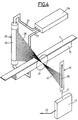
On se référera maintenant à la figure 4, pour expliquer le fonctionnement de l'un des moyens de commande des vérins, comportant l'une des sources lumineuses verticales 26. Dans l'exemple illustré sur la figure 4, la rampe lumineuse 26 est constituée par un tube fluorescent, dont l'axe longitudinal est parfaitement perpendiculaire au plan de référence inférieur constitué par la plaque 20 visible sur la figure 3. Le tube fluorescent 26 est alimenté en courant électrique par les connections 32, 33 reliées à un convertisseur haute fréquence 34. Le convertisseur 34 alimente le tube fluorescent 26 en courant à haute fréquence, par exemple de l'ordre de 25 kHz afin d'utiliser la rémanence de la décharge lumineuse dans le tube 26 pour obtenir une émission de lumière continue c'est-à-dire sans scintillations. Le tube fluorescent 26 comporte avantageusement un cache 35, définissant une fente qui laisse passer un mince pinceau lumineux vertical 28, dirigé perpendiculairement au tapis convoyeur 3 et vers celui-ci de façon à se trouver partiellement occulté par le bâti fixe 19 qui constitue un obstacle opaque pour le pinceau lumineux 28.Reference will now be made to FIG. 4, to explain the operation of one of the actuator control means, comprising one of the vertical
De l'autre côté du tapis convoyeur 3 par rapport à la source lumineuse 26, se trouve disposée une optique classique de focalisation 37 qui dirige le pinceau lumineux partiellement occulté sur une barrette linéaire de photodiodes 38 placée au foyer de l'optique 37, et comportant une pluralité de photodiodes 39 par exemple N photodiodes. Le faisceau lumineux 28 partiellement occulté par le bâti 19 devient un pinceau partiel 40 lorsqu'il atteint la barrette de photodiodes 38 illuminant ainsi un certain nombre des photodiodes 39 tandis que d'autres ne sont pas éclairées. Compte tenu de la position du bâti 19, il apparaît qu'une partie des diodes 39 se trouvant à l'extrémité supérieure de la barrette 38 ne reçoit pas de rayons lumineux puisqu'elle correspond à la zone occultée du pinceau lumineux 18 tandis que d'autres diodes 39 situées à la partie inférieure de la barrette 38 reçoivent les rayons lumineux du pinceau 40.On the other side of the
La barrette de photodiodes 38 est reliée par la connexion 41 à un microprocesseur 42 capable d'émettre par la connexion de sortie 43 un signal servant à la commande des vérins 15a, 15b et 15c.The
La détection de la position exacte du point de transition sur le réseau de photodiodes 38, est illustrée sur la figure 6, pour un réseau de photodiodes 39 de nombre pair. Les photodiodes 39 sont repérées par un numéro qui va de 1 à N, l'axe O du réseau de photodiodes se trouvant entre la diode N/2 et la diode N/2+1.The detection of the exact position of the transition point on the array of
L'amplitude lumineuse en fonction du numéro des diodes est représentée sur le graphe supérieur de la figure 6 qui montre qu'une partie des diodes 39, dans l'exemple illustré, les diodes de numéro 1 à N/2 sont totalement illuminées par le pinceau lumineux 40 (figure 4).The light amplitude as a function of the number of the diodes is represented on the upper graph of FIG. 6 which shows that part of the
Il en résulte une intensité lumineuse v illustrée en fonction des numéros des diodes sur le graphe inférieur de la figure 6 qui est constante pour toutes ces diodes. La diode de numéro N/2+1 qui se trouve sensiblement à l'endroit de la transition ne reçoit qu'une intensité lumineuse sensiblement inférieure à la moitié de l'intensité lumineuse v des diodes précédentes.This results in a light intensity v illustrated as a function of the numbers of the diodes on the lower graph of FIG. 6 which is constant for all these diodes. The diode of number N / 2 + 1 which is located substantially at the location of the transition receives only a light intensity substantially less than half the light intensity v of the preceding diodes.
Il est donc aisé de placer la transition entre deux photodiodes adjacentes, l'écart entre deux photodiodes étant généralement de l'ordre de 25 µm.It is therefore easy to place the transition between two adjacent photodiodes, the difference between two photodiodes generally being of the order of 25 μm.
L'asservissement est de préférence conçu de façon que la valeur de consigne pour les signaux de commande des vérins 15a, 15b, 15c place la transition sensiblement au centre O du réseau de photodiodes 38 et ce pour les deux réseaux de photodiodes 38, de façon à maintenir l'inclinaison du châssis de montage identique à celle du tapis convoyeur 3 c'est-à-dire à maintenir les plans de référence strictement parallèles au plan du tapis convoyeur 3. De plus la position des points de transition sur les réseaux de photodiodes 38 permet de mesurer à tout instant l'élévation du tapis transporteur 3 par rapport au plan de référence constitué par les plaques 20, 21.The servo is preferably designed so that the set value for the control signals of the
On notera que des moyens sont prévus pour arrêter le transfert des signaux de mesure lorsqu'un objet se trouvant sur le convoyeur occulte le faisceau lumineux.It will be noted that means are provided for stopping the transfer of the measurement signals when an object being on the conveyor obscures the light beam.
La figure 5 illustre de manière agrandie le dispositif optoélectronique 31 coopérant avec le rayon laser 30. On voit sur la figure 5 le capot de protection 44 de l'émetteur laser 29 qui émet le rayon laser 30. L'émetteur laser 29 est fixé sur un support solidaire du bâti 19 du tapis convoyeur 3 de façon à être rigoureusement perpendiculaire au plan du tapis convoyeur 3. Un système optique anamorphique 45 reçoit le rayon laser 30 et le transforme en un pinceau plan 46 sensiblement vertical dont la trace 47 est perpendiculaire à un réseau linéaire de photodiodes 48 placé dans le plan de référence supérieur du châssis de montage 14 perpendiculairement à l'axe du tapis convoyeur 3. Le réseau de photodiodes 48 est relié par la connexion 49 à un microprocesseur 50 qui émet un signal par la connexion de sortie 51, servant à la commande des vérins 15a, 15b, 15c.FIG. 5 illustrates in an enlarged manner the
Une variation d'inclinaison relative entre le plan de référence du châssis de montage 14 et le bâti 19 du tapis convoyeur 3 entraîne une variation angulaire du rayon laser 30 qui prend par exemple la position 30a illustrée sur la figure 5. Il en résulte un pinceau lumineux plan 46a dont la trace 47a s'est déplacée par rapport au réseau de photodiodes 48.A variation in relative inclination between the reference plane of the mounting
La détermination de la position de la tache lumineuse correspondant à la trace 47 sur le réseau de photodiodes 48 permet d'agir sur la commande des vérins 15a, 15b, 15c. On choisit de préférence pour la régulation une valeur de consigne telle que la position de la tache lumineuse correspondant à la trace 47 se trouve confondue avec l'axe du réseau de photodiodes 48.The determination of the position of the light spot corresponding to the
On va maintenant expliquer en se référant aux graphiques de la figure 7, la manière dont il est possible de déterminer la position exacte de la trace 47 sur le réseau de photodiodes 48.We will now explain, with reference to the graphs in FIG. 7, how it is possible to determine the exact position of the
Le graphe situé, dans la partie haute de la figure 7 montre la valeur de l'amplitude lumineuse de la tache lumineuse formée sur la barrette de photodiodes 48 par le pinceau lumineux 46 en fonction du numéro de la diode considérée, chaque diode étant repérée par un numéro allant de 1 à N. L'épaisseur du pinceau lumineux 46 n'étant pas infiniment faible, la tache lumineuse reçue par le réseau de photodiodes 48 n'est pas non plus infiniment petite. Elle présente l'aspect d'une courbe en cloche ayant pour axe de symétrie l'axe passant par le point O' sur la figure 7. Plusieurs diodes se trouvent donc simultanément éclairées par ladite tache lumineuse. Dans l'exemple illustré, le réseau de photodiodes 48 comporte un nombre pair de photodiodes. Le centre du réseau se trouve matérialisé par le point O situé entre la diode N/2 et la diode N/2+1.The graph located in the upper part of FIG. 7 shows the value of the light amplitude of the light spot formed on the array of
Le graphe inférieur de la figure 7 montre la valeur de l'intensité lumineuse v pour les différentes diodes illuminées par la tache lumineuse en fonction du numéro des diodes. Pour chaque diode le centre de celle-ci est repéré par le point Pi correspondant à la diode d'ordre i celle-ci recevant une intensité lumineuse vi.The lower graph of FIG. 7 shows the value of the light intensity v for the different diodes illuminated by the light spot as a function of the number of diodes. For each diode, the center thereof is identified by the point P i corresponding to the diode of order i, the latter receiving a light intensity v i .
Le microprocesseur 50 est capable de déterminer la distance entre le centre de la tache lumineuse O' et le centre du réseau O pour le réseau de diodes de nombre pair.The
En admettant que la courbe de répartition lumineuse soit symétrique, ce qui est le cas en pratique, il est possible d'écrire l'équation
L'inconnue recherchée x = ![]()

![]()

- x est la distance entre le centre O du réseau de photodiodes pour un nombre pair de diodes et le centre O' de la tache lumineuse;
- e est la distance entre les centres de deux photodiodes voisines;
- ni est le numéro d'une diode d'indice i;
- N est le nombre total de photodiodes d'un réseau qui, dans l'exemple est un nombre pair soit en général 128 ou 512;
- et vi est l'intensité lumineuse reçue par la photodiode i.
- x is the distance between the center O of the array of photodiodes for an even number of diodes and the center O 'of the light spot;
- e is the distance between the centers of two neighboring photodiodes;
- n i is the number of a diode with index i;
- N is the total number of photodiodes of an array which, in the example is an even number, generally 128 or 512;
- and v i is the light intensity received by photodiode i.
Pour maintenir l'inclinaison du châssis de montage 14 rigoureusement égale à tout instant à l'inclinaison du tapis convoyeur 3, on définit alors une valeur de consigne pour la régulation qui est de préférence telle que l'axe O' de la tacle lumineuse se trouve sensiblement confondu avec l'axe O du réseau de photodiodes 39.To maintain the inclination of the mounting
La figure 8 reprend les principaux éléments du dispositif de l'invention. On y retrouve en effet les deux sources lumineuses 26 schématiquement indiquées comme étant montées perpendiculairement au plan de référence inférieur constitué par la plaque 20. Les pinceaux lumineux focalisés par le dispositif optique 37 occultés par le bâti 19 viennent éclairer la portion inférieure des réseaux de photodiodes 38 disposés perpendiculairement au plan de référence inférieur matérialisé par la plaque 21. Les signaux émis, après avoir été traités par les microprocesseurs 42, associés chacun à un réseau de photodiodes 39, sont amenés à un calculateur 52. Dans les mêmes conditions, le rayon laser 30 provoque une tache lumineuse sur le réseau de photodiodes 48 solidaire du plan de référence supérieur matérialisé par exemple par une barre horizontale 23. Le signal émis, après avoir été traité par le microprocesseur 50 est également amené au calculateur 52. Celui-ci comporte un panneau d'affichage 53 permettant de contrôler à tout instant le fonctionnement du dispositif et l'émission des signaux provenant des microprocesseurs 42 et 50. Les signaux de sortie du calculateur 52 sont amenés par les connexions 54 par l'intermédiaire de dispositifs à commande manuelle 55 sur des amplificateurs de puissance 56 chacun relié par la connexion 57 à l'un des vérins 15a, 15b et 15c.Figure 8 shows the main elements of the device of the invention. There are in fact the two
Grâce au châssis de montage de la présente invention, il est possible de maintenir la structure indéformable du châssis en position fixe par rapport au tapis convoyeur 3, quelle que soit l'inclinaison de celui-ci et ce d'une manière simple et parfaitement fiable même dans un environnement hostile comme celui d'une installation de fabrication de bouteilles en verre. Le tapis convoyeur 3 n'est nullement prisonnier du dispositif qui peut au contraire être aisément retiré et reposé sans nécessiter l'arrêt de l'ensemble de l'installation.Thanks to the mounting chassis of the present invention, it is possible to maintain the non-deformable structure of the chassis in a fixed position relative to the
Tous les dispositifs de mesure et de contrôle souhaités peuvent aisément être montés à l'intérieur de la structure indéformable du châssis de montage de l'invention de façon à effectuer les contrôles désirés pour les bouteilles en verre se déplaçant sur le tapis convoyeur.All the desired measurement and control devices can easily be mounted inside the non-deformable structure of the mounting frame of the invention so as to carry out the desired controls for the glass bottles moving on the conveyor belt.
Claims (10)
- Mounting framework for contactless testing devices for moulded objects, in particular glass objects, at high temperature, in particular bottles, placed on a conveyor belt (3) driven with respect to a frame (19) with adjustable inclination in the same vertical plane, comprising rigid columns (22) defining a nondeformable structure straddling the conveyor belt (3) in the manner of a bridge, characterized in that the said structure defines two parallel reference planes, is not connected to the frame (19) of the conveyor (3) and is supported by means of three jacks (15a, 15b, 15c) with controlled displacements; and in that the said framework comprises at least one device including a light source emitting a light beam whose characteristics depend on the inclination of the conveyor belt (3), interacting with a network of photodiodes capable of emitting an electrical signal for controlling the said jacks in order to maintain the aforementioned reference planes of the framework continuously parallel to the plane of the conveyor belt (3) whatever its inclination.
- Framework according to Claim 1, characterized in that the three jacks (15a, 15b and 15c) each include a rod (16) which can move in translation, connected by a block (18) of elastic material to a support base (17) of the framework.
- Framework according to Claim 2, characterized in that each support base (17) includes an upper end which fits into a housing in the framework.
- Framework according to Claim 3, characterized in that the upper end (17a) of the support bases (17), and the corresponding housings, are of frustoconical shape.
- Framework according to any one of the preceding claims, characterized in that it comprises two rectilinear light sources (26) perpendicular to the reference planes, spaced apart from each other, each emitting a pencil of white light (28) partially occulted by the frame (19) of the conveyor belt (3), interacting with two linear arrays (38) of photodiodes (39) placed at the focus of an optical focussing device (37) so that the said arrays (38) are illuminated by both partially occulted light pencils (28) and means for determining at any instant the number of photodiodes (39) illuminated in each array (38) and in order to emit signals for controlling the jacks (15a, 15b, 15c) in order to maintain the reference plane parallel to the conveyor belt (3).
- Framework according to Claim 5, characterized in that the light sources (26) are fluorescent tubes powered at a frequency greater than the afterglow of the said fluorescent tubes.
- Framework according to either of Claims 5 or 6, characterized in that each array of photodiodes (38) is associated with a microprocessor (42) receiving the signals emitted by the arrays of photodiodes (38) and capable of storing set-point values of the position of the various light beams, these set-point values being chosen so that the transition signal corresponds each time substantially to the median zone of each array of photodiodes.
- Framework according to any one of Claims 5 to 7, characterized in that it furthermore comprises a light emitter (29) solidly fixed to the frame (19) of the conveyor belt (3) so as to emit a thin light beam (30) exactly perpendicular to the plane of the conveyor belt (3) and interacting with an anamorphic optical system (45) solidly fixed to the framework, capable of converting the thin light beam (30) into a planar light pencil (46) substantially parallel to the vertical plane in which the inclination of the frame (19) of the conveyor belt (3) is adjustable; a linear array (48) of photodiodes arranged perpendicular to the trace (47) of the said planar light pencil (46); and means for determining at any instant the diode or diodes of the said array (48) illuminated by the said pencil and in order to emit a signal for controlling the jacks (15a, 15b, 15c) in order to maintain the reference plane parallel to the plane of the conveyor belt (3).
- Framework according to Claim 8, characterized in that the array of photodiodes (48) is associated with a microprocessor (50) receiving the signals emitted by the array of photodiodes (48) and capable of storing a set-point value of the position of the trace (47) of the light pencil (46), this set-point value being chosen so that the trace (47) of the light pencil (46) substantially corresponds to the axis of the linear array of photodiodes (48).
- Framework according to either of Claims 8 or 9, characterized in that the light emitter (29) is a laser emitter.
Applications Claiming Priority (2)
| Application Number | Priority Date | Filing Date | Title |
|---|---|---|---|
| FR9113414A FR2683372B1 (en) | 1991-10-30 | 1991-10-30 | MOUNTING CHASSIS FOR NON-CONTACT CONTROL DEVICES OF MOLDED OBJECTS, PARTICULARLY GLASS, AT HIGH TEMPERATURE. |
| FR9113414 | 1991-10-30 |
Publications (2)
| Publication Number | Publication Date |
|---|---|
| EP0540419A1 EP0540419A1 (en) | 1993-05-05 |
| EP0540419B1 true EP0540419B1 (en) | 1997-05-14 |
Family
ID=9418474
Family Applications (1)
| Application Number | Title | Priority Date | Filing Date |
|---|---|---|---|
| EP92402934A Expired - Lifetime EP0540419B1 (en) | 1991-10-30 | 1992-10-29 | Frame for mounting devices for non-contact high-temperature inspection of moulded articles, particularly of glass |
Country Status (7)
| Country | Link |
|---|---|
| US (1) | US5270535A (en) |
| EP (1) | EP0540419B1 (en) |
| AT (1) | ATE153168T1 (en) |
| CA (1) | CA2077710A1 (en) |
| DE (1) | DE69219723T2 (en) |
| ES (1) | ES2103911T3 (en) |
| FR (1) | FR2683372B1 (en) |
Families Citing this family (7)
| Publication number | Priority date | Publication date | Assignee | Title |
|---|---|---|---|---|
| US5637864A (en) * | 1994-09-17 | 1997-06-10 | Owens-Brockway Glass Container Inc. | Optical inspection of translucent containers for vertical checks and split seams in the container sidewalls |
| EP0979153A4 (en) * | 1996-06-04 | 2002-10-30 | Inex Inc Doing Business As Ine | System and method for stress detection in a molded container |
| EP1886765A1 (en) * | 2007-08-01 | 2008-02-13 | Kama GmbH | Tool carrier device and device for processing flat blanks |
| EP3046404B1 (en) * | 2013-09-09 | 2018-01-10 | Fuji Machine Mfg. Co., Ltd. | Manufacturing work machine |
| FR3056296B1 (en) * | 2016-09-19 | 2018-10-19 | Tiama | INSTALLATION FOR THE OPTICAL INSPECTION OF GLASS CONTAINERS OUTPUT OF FORMING MACHINE |
| EP3899598A1 (en) * | 2018-12-17 | 2021-10-27 | Sidel Participations | Device for optically detecting a positioning or shape defect of a hollow body in a conveyor of a thermal conditioning unit |
| CN111842183B (en) * | 2020-07-27 | 2021-09-28 | 深圳市维图视技术有限公司 | Bottle body detection device and bottle body detection method |
Family Cites Families (6)
| Publication number | Priority date | Publication date | Assignee | Title |
|---|---|---|---|---|
| US3245533A (en) * | 1963-12-19 | 1966-04-12 | Owens Illinois Glass Co | Inspecting glass container for horizontal checks |
| US3956632A (en) * | 1975-06-30 | 1976-05-11 | Fmc Corporation | Conveyor belt position monitoring device |
| US4239116A (en) * | 1978-10-27 | 1980-12-16 | Solbern Corp. | Apparatus for diverting articles |
| US4693376A (en) * | 1981-05-26 | 1987-09-15 | National Can Corporation | Apparatus for inspecting containers |
| US4476533A (en) * | 1981-07-08 | 1984-10-09 | Ball Corporation | Glassware gauging system |
| FR2571143B1 (en) * | 1984-10-02 | 1988-03-25 | Languedoc Verrerie | METHOD AND DEVICE FOR NON-CONTACT CONTROL OF OBJECTS MANUFACTURED AUTOMATICALLY AT HIGH THROUGHPUT |
-
1991
- 1991-10-30 FR FR9113414A patent/FR2683372B1/en not_active Expired - Fee Related
-
1992
- 1992-10-28 US US07/967,874 patent/US5270535A/en not_active Expired - Fee Related
- 1992-10-29 EP EP92402934A patent/EP0540419B1/en not_active Expired - Lifetime
- 1992-10-29 AT AT92402934T patent/ATE153168T1/en not_active IP Right Cessation
- 1992-10-29 ES ES92402934T patent/ES2103911T3/en not_active Expired - Lifetime
- 1992-10-29 DE DE69219723T patent/DE69219723T2/en not_active Expired - Fee Related
- 1992-10-30 CA CA002077710A patent/CA2077710A1/en not_active Abandoned
Also Published As
| Publication number | Publication date |
|---|---|
| FR2683372B1 (en) | 1994-02-04 |
| ATE153168T1 (en) | 1997-05-15 |
| EP0540419A1 (en) | 1993-05-05 |
| DE69219723T2 (en) | 1998-01-02 |
| CA2077710A1 (en) | 1993-05-01 |
| FR2683372A1 (en) | 1993-05-07 |
| DE69219723D1 (en) | 1997-06-19 |
| US5270535A (en) | 1993-12-14 |
| ES2103911T3 (en) | 1997-10-01 |
Similar Documents
| Publication | Publication Date | Title |
|---|---|---|
| EP0005683B1 (en) | Process of manufacturing a planar-convex microlens on at least one end face of an optical fiber, the lens being bonded with its planar face to said end face | |
| EP0665951B1 (en) | Process and device for inspection of a transparent material | |
| EP1548422A1 (en) | Method and device for measuring light absorption or scattering of biological samples | |
| EP0540419B1 (en) | Frame for mounting devices for non-contact high-temperature inspection of moulded articles, particularly of glass | |
| EP0320326B1 (en) | Process and means for contactless controlling the geometric outlines | |
| EP0080418A1 (en) | Method and device for checking a fuel assembly of a nuclear reactor | |
| FR2883300A1 (en) | APPARATUS FOR REMOVING FIBERS FROM FIBERS OF TEXTILE FIBERS OF CURING MATERIAL, EG COTTON, SYNTHETIC FIBERS AND EQUIVALENT FIBERS | |
| EP0004690A1 (en) | Method and device for the continuous casting of metal | |
| WO2018051046A1 (en) | Installation for optical inspection of glass containers at the outlet of a forming machine | |
| CH643618A5 (en) | RAILWAY SITE MACHINE. | |
| FR2700611A1 (en) | Method and device for dimensionally controlling the profile of long products | |
| FR2499718A1 (en) | METHOD AND DEVICE FOR DETECTING SURFACE DEFECTS OF MECHANICAL PARTS, PARTICULARLY CURVED SURFACE PARTS | |
| FR2591354A1 (en) | METHOD FOR RECIPROCALLY POSITIONING AN OPTICAL FIBER AND A SEMICONDUCTOR LASER, AND POSITIONING APPARATUS USING THE SAME | |
| EP0553004A1 (en) | Device for measuring the reflection properties of a transparent substrate, especially glass, with a partially reflecting layer | |
| FR2762083A1 (en) | OPTICAL METHOD FOR MEASURING THE WALL THICKNESS AND / OR OVALIZATION OF A CONTAINER AND DEVICE USING THE SAME | |
| FR2481445A1 (en) | Measuring geometrical dimensions of optical fibre - during mfr. automatically to obtain electrical signals for controlling operational parameters of mfr. | |
| FR2629909A1 (en) | METHOD AND APPARATUS FOR MEASURING MICRO-DISTANCES | |
| FR2803027A1 (en) | Optical measurement technique for determination of the wall thickness of a transparent container uses two light beams derived from an interferometer to determine the optical path lengths to a target and a reference reflector | |
| FR2674526A1 (en) | Device with a source of microwave-induced ultraviolet radiation for the polymerisation of photopolymerisable objects | |
| FR2688619A1 (en) | GAMMA BEAM COLLIMATION ASSEMBLY EMITTED BY AN IRRADIA COMBUSTIBLE ELEMENT WAFER AND EXAMINED BY A DETECTOR. | |
| FR3056297A1 (en) | DEVICE FOR THE OPTICAL INSPECTION OF GLASS CONTAINERS AT THE OUTPUT OF A FORMING MACHINE | |
| FR2713758A1 (en) | Lens mounting frame internal contour automatic determining appts. | |
| FR2670908A1 (en) | DEVICE FOR THE NON - CONTACT DETECTION OF MOVING GLASS SHEETS. | |
| FR2739982A1 (en) | Single or multiple laser beam homogenising apparatus for e.g. optical pumping of optical fibre | |
| WO2024074241A1 (en) | Optical substrate having integrated antennas, and spectrometer comprising same |
Legal Events
| Date | Code | Title | Description |
|---|---|---|---|
| PUAI | Public reference made under article 153(3) epc to a published international application that has entered the european phase |
Free format text: ORIGINAL CODE: 0009012 |
|
| AK | Designated contracting states |
Kind code of ref document: A1 Designated state(s): CH ES FR GB GR IT LI LU MC NL SE |
|
| 17P | Request for examination filed |
Effective date: 19931026 |
|
| 17Q | First examination report despatched |
Effective date: 19950307 |
|
| GRAG | Despatch of communication of intention to grant |
Free format text: ORIGINAL CODE: EPIDOS AGRA |
|
| RBV | Designated contracting states (corrected) |
Designated state(s): AT BE CH DE DK ES FR GB IE IT LI LU NL PT SE |
|
| GRAH | Despatch of communication of intention to grant a patent |
Free format text: ORIGINAL CODE: EPIDOS IGRA |
|
| GRAH | Despatch of communication of intention to grant a patent |
Free format text: ORIGINAL CODE: EPIDOS IGRA |
|
| GRAA | (expected) grant |
Free format text: ORIGINAL CODE: 0009210 |
|
| AK | Designated contracting states |
Kind code of ref document: B1 Designated state(s): AT BE CH DE DK ES FR GB IE IT LI LU NL PT SE |
|
| REF | Corresponds to: |
Ref document number: 153168 Country of ref document: AT Date of ref document: 19970515 Kind code of ref document: T |
|
| REG | Reference to a national code |
Ref country code: CH Ref legal event code: EP |
|
| REF | Corresponds to: |
Ref document number: 69219723 Country of ref document: DE Date of ref document: 19970619 |
|
| ITF | It: translation for a ep patent filed |
Owner name: STUDIO TORTA S.R.L. |
|
| GBT | Gb: translation of ep patent filed (gb section 77(6)(a)/1977) |
Effective date: 19970815 |
|
| REG | Reference to a national code |
Ref country code: CH Ref legal event code: NV Representative=s name: KIRKER & CIE SA |
|
| REG | Reference to a national code |
Ref country code: ES Ref legal event code: FG2A Ref document number: 2103911 Country of ref document: ES Kind code of ref document: T3 |
|
| PG25 | Lapsed in a contracting state [announced via postgrant information from national office to epo] |
Ref country code: ES Free format text: LAPSE BECAUSE OF EXPIRATION OF PROTECTION Effective date: 19971030 |
|
| REG | Reference to a national code |
Ref country code: PT Ref legal event code: SC4A Free format text: AVAILABILITY OF NATIONAL TRANSLATION Effective date: 19970814 |
|
| PLBE | No opposition filed within time limit |
Free format text: ORIGINAL CODE: 0009261 |
|
| STAA | Information on the status of an ep patent application or granted ep patent |
Free format text: STATUS: NO OPPOSITION FILED WITHIN TIME LIMIT |
|
| 26N | No opposition filed | ||
| PGFP | Annual fee paid to national office [announced via postgrant information from national office to epo] |
Ref country code: IE Payment date: 19981021 Year of fee payment: 7 |
|
| PGFP | Annual fee paid to national office [announced via postgrant information from national office to epo] |
Ref country code: GB Payment date: 19981023 Year of fee payment: 7 |
|
| PGFP | Annual fee paid to national office [announced via postgrant information from national office to epo] |
Ref country code: SE Payment date: 19981026 Year of fee payment: 7 |
|
| PGFP | Annual fee paid to national office [announced via postgrant information from national office to epo] |
Ref country code: PT Payment date: 19981029 Year of fee payment: 7 Ref country code: DK Payment date: 19981029 Year of fee payment: 7 |
|
| PGFP | Annual fee paid to national office [announced via postgrant information from national office to epo] |
Ref country code: AT Payment date: 19981030 Year of fee payment: 7 |
|
| PGFP | Annual fee paid to national office [announced via postgrant information from national office to epo] |
Ref country code: LU Payment date: 19981105 Year of fee payment: 7 |
|
| PGFP | Annual fee paid to national office [announced via postgrant information from national office to epo] |
Ref country code: BE Payment date: 19981118 Year of fee payment: 7 |
|
| PG25 | Lapsed in a contracting state [announced via postgrant information from national office to epo] |
Ref country code: LU Free format text: LAPSE BECAUSE OF NON-PAYMENT OF DUE FEES Effective date: 19991029 Ref country code: IE Free format text: LAPSE BECAUSE OF NON-PAYMENT OF DUE FEES Effective date: 19991029 Ref country code: GB Free format text: LAPSE BECAUSE OF NON-PAYMENT OF DUE FEES Effective date: 19991029 Ref country code: DK Free format text: LAPSE BECAUSE OF NON-PAYMENT OF DUE FEES Effective date: 19991029 Ref country code: AT Free format text: LAPSE BECAUSE OF NON-PAYMENT OF DUE FEES Effective date: 19991029 |
|
| PG25 | Lapsed in a contracting state [announced via postgrant information from national office to epo] |
Ref country code: SE Free format text: THE PATENT HAS BEEN ANNULLED BY A DECISION OF A NATIONAL AUTHORITY Effective date: 19991030 |
|
| PG25 | Lapsed in a contracting state [announced via postgrant information from national office to epo] |
Ref country code: BE Free format text: LAPSE BECAUSE OF NON-PAYMENT OF DUE FEES Effective date: 19991031 |
|
| BERE | Be: lapsed |
Owner name: VERRERIE DU LANGUEDOC ET CIE Effective date: 19991031 |
|
| PG25 | Lapsed in a contracting state [announced via postgrant information from national office to epo] |
Ref country code: PT Free format text: LAPSE BECAUSE OF NON-PAYMENT OF DUE FEES Effective date: 20000430 |
|
| EUG | Se: european patent has lapsed |
Ref document number: 92402934.1 |
|
| GBPC | Gb: european patent ceased through non-payment of renewal fee |
Effective date: 19991029 |
|
| REG | Reference to a national code |
Ref country code: DK Ref legal event code: EBP |
|
| REG | Reference to a national code |
Ref country code: PT Ref legal event code: MM4A Free format text: LAPSE DUE TO NON-PAYMENT OF FEES Effective date: 20000430 |
|
| REG | Reference to a national code |
Ref country code: IE Ref legal event code: MM4A |
|
| PGFP | Annual fee paid to national office [announced via postgrant information from national office to epo] |
Ref country code: FR Payment date: 20001004 Year of fee payment: 9 |
|
| PGFP | Annual fee paid to national office [announced via postgrant information from national office to epo] |
Ref country code: DE Payment date: 20001016 Year of fee payment: 9 |
|
| PGFP | Annual fee paid to national office [announced via postgrant information from national office to epo] |
Ref country code: NL Payment date: 20001031 Year of fee payment: 9 |
|
| PGFP | Annual fee paid to national office [announced via postgrant information from national office to epo] |
Ref country code: CH Payment date: 20010116 Year of fee payment: 9 |
|
| REG | Reference to a national code |
Ref country code: ES Ref legal event code: FD2A Effective date: 20010301 |
|
| PG25 | Lapsed in a contracting state [announced via postgrant information from national office to epo] |
Ref country code: LI Free format text: LAPSE BECAUSE OF NON-PAYMENT OF DUE FEES Effective date: 20011031 Ref country code: CH Free format text: LAPSE BECAUSE OF NON-PAYMENT OF DUE FEES Effective date: 20011031 |
|
| PG25 | Lapsed in a contracting state [announced via postgrant information from national office to epo] |
Ref country code: NL Free format text: LAPSE BECAUSE OF NON-PAYMENT OF DUE FEES Effective date: 20020501 |
|
| REG | Reference to a national code |
Ref country code: CH Ref legal event code: PL |
|
| PG25 | Lapsed in a contracting state [announced via postgrant information from national office to epo] |
Ref country code: FR Free format text: LAPSE BECAUSE OF NON-PAYMENT OF DUE FEES Effective date: 20020628 |
|
| NLV4 | Nl: lapsed or anulled due to non-payment of the annual fee |
Effective date: 20020501 |
|
| PG25 | Lapsed in a contracting state [announced via postgrant information from national office to epo] |
Ref country code: DE Free format text: LAPSE BECAUSE OF NON-PAYMENT OF DUE FEES Effective date: 20020702 |
|
| REG | Reference to a national code |
Ref country code: FR Ref legal event code: ST |
|
| PG25 | Lapsed in a contracting state [announced via postgrant information from national office to epo] |
Ref country code: IT Free format text: LAPSE BECAUSE OF NON-PAYMENT OF DUE FEES;WARNING: LAPSES OF ITALIAN PATENTS WITH EFFECTIVE DATE BEFORE 2007 MAY HAVE OCCURRED AT ANY TIME BEFORE 2007. THE CORRECT EFFECTIVE DATE MAY BE DIFFERENT FROM THE ONE RECORDED. Effective date: 20051029 |