EP0540211B1 - Apparatus for filling an endodontically prepared tooth root canal - Google Patents
Apparatus for filling an endodontically prepared tooth root canal Download PDFInfo
- Publication number
- EP0540211B1 EP0540211B1 EP92309372A EP92309372A EP0540211B1 EP 0540211 B1 EP0540211 B1 EP 0540211B1 EP 92309372 A EP92309372 A EP 92309372A EP 92309372 A EP92309372 A EP 92309372A EP 0540211 B1 EP0540211 B1 EP 0540211B1
- Authority
- EP
- European Patent Office
- Prior art keywords
- carrier
- shaft
- displacing
- root canal
- filling material
- Prior art date
- Legal status (The legal status is an assumption and is not a legal conclusion. Google has not performed a legal analysis and makes no representation as to the accuracy of the status listed.)
- Expired - Lifetime
Links
- 239000000463 material Substances 0.000 claims description 67
- 210000004262 dental pulp cavity Anatomy 0.000 claims description 51
- 229920001169 thermoplastic Polymers 0.000 claims description 10
- 239000004416 thermosoftening plastic Substances 0.000 claims description 10
- 210000003813 thumb Anatomy 0.000 claims description 4
- 210000003811 finger Anatomy 0.000 claims description 3
- 238000007789 sealing Methods 0.000 claims description 3
- 239000004020 conductor Substances 0.000 claims description 2
- 210000005224 forefinger Anatomy 0.000 claims description 2
- 239000000899 Gutta-Percha Substances 0.000 description 37
- 240000000342 Palaquium gutta Species 0.000 description 37
- 229920000588 gutta-percha Polymers 0.000 description 37
- 239000000945 filler Substances 0.000 description 8
- 238000006073 displacement reaction Methods 0.000 description 7
- 238000000034 method Methods 0.000 description 7
- XLOMVQKBTHCTTD-UHFFFAOYSA-N Zinc monoxide Chemical compound [Zn]=O XLOMVQKBTHCTTD-UHFFFAOYSA-N 0.000 description 6
- 210000001114 tooth apex Anatomy 0.000 description 6
- HEDRZPFGACZZDS-UHFFFAOYSA-N Chloroform Chemical compound ClC(Cl)Cl HEDRZPFGACZZDS-UHFFFAOYSA-N 0.000 description 4
- 229910001220 stainless steel Inorganic materials 0.000 description 4
- 239000012815 thermoplastic material Substances 0.000 description 4
- 239000000853 adhesive Substances 0.000 description 3
- 230000001070 adhesive effect Effects 0.000 description 3
- 210000004268 dentin Anatomy 0.000 description 3
- 239000010935 stainless steel Substances 0.000 description 3
- 239000001993 wax Substances 0.000 description 3
- 239000011787 zinc oxide Substances 0.000 description 3
- RRHGJUQNOFWUDK-UHFFFAOYSA-N Isoprene Chemical compound CC(=C)C=C RRHGJUQNOFWUDK-UHFFFAOYSA-N 0.000 description 2
- 239000004568 cement Substances 0.000 description 2
- 210000003298 dental enamel Anatomy 0.000 description 2
- 239000003605 opacifier Substances 0.000 description 2
- 229920001195 polyisoprene Polymers 0.000 description 2
- 239000004150 EU approved colour Substances 0.000 description 1
- 239000004110 Zinc silicate Substances 0.000 description 1
- 239000000654 additive Substances 0.000 description 1
- 239000003963 antioxidant agent Substances 0.000 description 1
- 238000010420 art technique Methods 0.000 description 1
- 230000000903 blocking effect Effects 0.000 description 1
- 239000000969 carrier Substances 0.000 description 1
- 238000007796 conventional method Methods 0.000 description 1
- 238000013461 design Methods 0.000 description 1
- 238000007598 dipping method Methods 0.000 description 1
- 210000000416 exudates and transudate Anatomy 0.000 description 1
- 229910001385 heavy metal Inorganic materials 0.000 description 1
- 238000003780 insertion Methods 0.000 description 1
- 230000037431 insertion Effects 0.000 description 1
- 239000000155 melt Substances 0.000 description 1
- 229910052751 metal Inorganic materials 0.000 description 1
- 239000002184 metal Substances 0.000 description 1
- 239000000203 mixture Substances 0.000 description 1
- 239000002991 molded plastic Substances 0.000 description 1
- 210000000944 nerve tissue Anatomy 0.000 description 1
- 229940006093 opthalmologic coloring agent diagnostic Drugs 0.000 description 1
- 230000037361 pathway Effects 0.000 description 1
- 239000004033 plastic Substances 0.000 description 1
- 229920000642 polymer Polymers 0.000 description 1
- 239000002861 polymer material Substances 0.000 description 1
- 238000012545 processing Methods 0.000 description 1
- 229920005989 resin Polymers 0.000 description 1
- 239000011347 resin Substances 0.000 description 1
- 239000007787 solid Substances 0.000 description 1
- 239000000126 substance Substances 0.000 description 1
- 150000003467 sulfuric acid derivatives Chemical class 0.000 description 1
- 210000001519 tissue Anatomy 0.000 description 1
- 239000002023 wood Substances 0.000 description 1
- XSMMCTCMFDWXIX-UHFFFAOYSA-N zinc silicate Chemical compound [Zn+2].[O-][Si]([O-])=O XSMMCTCMFDWXIX-UHFFFAOYSA-N 0.000 description 1
- 235000019352 zinc silicate Nutrition 0.000 description 1
Images

Classifications
-
- A—HUMAN NECESSITIES
- A61—MEDICAL OR VETERINARY SCIENCE; HYGIENE
- A61C—DENTISTRY; APPARATUS OR METHODS FOR ORAL OR DENTAL HYGIENE
- A61C5/00—Filling or capping teeth
- A61C5/50—Implements for filling root canals; Methods or instruments for medication of tooth nerve channels
-
- A—HUMAN NECESSITIES
- A61—MEDICAL OR VETERINARY SCIENCE; HYGIENE
- A61C—DENTISTRY; APPARATUS OR METHODS FOR ORAL OR DENTAL HYGIENE
- A61C5/00—Filling or capping teeth
- A61C5/50—Implements for filling root canals; Methods or instruments for medication of tooth nerve channels
- A61C5/55—Implements for filling root canals; Methods or instruments for medication of tooth nerve channels with heating means, e.g. for heating gutta percha
Definitions
- the present invention relates to apparatus for filling an endodontically prepared root canal.
- one step of the procedure involves the filling of the root canal after it has been endodontically prepared, i.e., reamed out to remove pulpal tissue.
- Endodontically prepared root canals are filled with a material commonly referred to as gutta percha, which is commercially available in the form of "points" which are elongated, tapered articles having a length of approximately 28 mm and having a diameter of between approximately 0.15 to 1.4 mm. These "points” may be held with tweezers or the like and inserted into the root canal. Once in place, they may be heated with a warmed instrument. A pick-shaped instrument commonly referred to as a condenser is then used gradually to push the softened gutta percha material down into the root canal.
- gutta percha a material commonly referred to as gutta percha
- a gutta percha gun has been proposed, this being a device which heats a bulk quantity of gutta percha material and then forces the material through a hollow needle to place it in the root canal - see US-A-4357136 for example.
- US-A-4758156 and 4894011 both show the forming of gutta percha material about an elongated shaft made of plastic or metal.
- the shaft can be manually placed in the prepared root canal, and then the shaft is broken leaving a portion of the broken shaft along with the surrounding gutta percha material in place filling the root canal.
- the gutta percha guns can be very expensive and are bulky to use and the devices having a shaft imbedded in the gutta percha material are undesirable because they leave foreign material, namely the broken shaft, in the root canal. This foreign material can be very difficult to remove in the event that there is a failure of the root canal operation and it is desired to remove the filling material.
- a pre-filled apparatus for placing thermoplastic filling material in an endodontically prepared root canal comprising, a hollow carrier having a distal end and a proximal end and having a cylindrical carrier bore defined therethrough from said distal end to said proximal end; a plug of thermoplastic filling material occupying at least a distal portion of said carrier bore and terminating adjacent said distal end of said carrier, said distal portion being less than all of said carrier bore thus defining a proximal portion of said carrier bore unoccupied by said plug; and a displacing shaft, received in said proximal portion of said carrier bore, for displacing said plug of thermoplastic filling material from a distal end of said carrier bore into said endodontically prepared root canal.
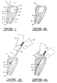
- this shows a tooth 10 having a crown portion 12 and a root portion 14 made up of first and second roots 16,18.
- the tooth is composed of dentine material 20 with the crown 12 being covered by enamel 22.
- FIG. 1 a portion of the enamel and dentine have been broken away from the crown 12 to form an access opening 24 providing access to the interior 26 of the crown.
- Each root canal such as root canal 28 ends in an apical foramen 36 which is a small opening through which the nerve tissue originally entered the tooth.
- the apical foramen 36 of root canal 28 has been closed in a conventional manner by taking a gutta percha point and dipping it in chloroform, then inserting the point into the canal so that the lower end of the point will conform to the shape of the canal adjacent the apical foramen 36.
- the point is then removed and the chloroform is allowed to evaporate.
- the point is then coated with a sealing cement (such as Kerr pulp canal sealer or Grossman root canal cement, which acts as an adhesive to help bond the filling material to the walls of the root canal) and reinserted.
- a heated instrument is then used to cut off the molded end portion, thus leaving an initial gutta percha block or plug 38 as shown.
- This apical filling of gutta percha is subsequently molded into the canal area by compressing its upper surface with a condenser instrument.
- FIG 3 the pre-filled gutta percha placement apparatus 40 of the present invention is shown having been inserted in the tooth 10 to a position adjacent the opening 32 to root canal 28.
- the apparatus 40 includes a hollow disposable carrier 42 containing and storing a plug 44 of filling material and a displacing shaft 46 having a fingertip handle 48 attached to an outer end portion 74 ( Figure 7) thereof and shown being grasped between the thumb 50 and forefinger 52 of a physician as shown in phantom lines.
- Figure 7 shows an elevation sectioned view of the apparatus 40 in a position analogous to that shown in Figure 3 prior to displacement of the filling material 44 from the carrier 42, which is constructed from a straight segment of hollow tubing and has a distal end 54 and a proximal end 56.
- the carrier 42 has a straight cylindrical bore 58 and outer surface 62, of constant diameters 60 and 64 respectively.
- the pre-filled carrier 42 may be provided separate from the displacing shaft 46, so that the carrier 42 and displacing shaft 46 are assembled by the physician shortly prior to use, or the carrier 42 and displacing shaft 46 may come preassembled as shown in Figure 7.
- the plug of filling material indicated by 44A occupies the entire carrier bore 58.
- the plug of filling material designated as 44B occupies only a first portion 64 which may also be referred to as a distal portion 64 of carrier bore 58 adjacent the distal end 54 of carrier 42 thus leaving an unoccupied proximal portion 66 of carrier bore 58.
- the second portion 66 of carrier bore 58 preferably has a length of at least 2 mm to accommodate the overlapping engagement through distance 80 of approximately that same length as shown in Figure 7.
- the plug of filling material 44A or 44B can be said to occupy a distal portion of the carrier bore 58 adjacent the distal end 54.
- that distal portion is the entirety of the carrier bore 58
- that distal portion is less than the entire bore and only includes the portion 64 indicated in Figure 6.
- Figure 7 illustrates the preferred manner of assembly of displacing shaft 46 with either form of pre-filled carrier as shown in either Figures 5 or 6.
- an inner end portion 68 of displacing shaft 46 is first heated, preferably over an open flame such as a Bunsen burner, and is then inserted into the proximal end 56 of carrier bore 58 into engagement with the filler material 44 thus softening a small portion of the filler material 44 which will flow up through the slight annular clearance between displacing shaft 46 and carrier bore 58 thus forming a thin cylindrical portion 70 of filling material between the carrier bore 58 and the outer surface 72 of displacing shaft 46.
- the tackiness of the gutta percha material causes it to adhere to the inner end 68 of displacing shaft 46 so as to hold the displacing shaft 46 and pre-filled carrier 42 together as they are being handled by the physician and placed in operative relationship to the tooth 10 as illustrated in Figures 3 and 4.
- the shaft 46 could be magnetized to aid in holding the carrier 42.
- the displacing shaft 46 is sufficiently closely received within the carrier bore 58 to displace the plug of filling material 44 therefrom after the plug 44 has been heated without any separate sealing ring between the displacing shaft 46 and the carrier bore 58.
- the carrier 42 has a length 76 to 16 mm.
- the shaft 46 has a length 78 extending beyond handle 48 of 18 mm with an overlap 80 of approximately 2 mm.
- the handle 48 has a length 82 of approximately 6 mm. This provides an overall length 84 for the apparatus 40 when in the extended position of Figure 7 of approximately 38 mm. When the apparatus 40 is collapsed to the position shown in Figure 4 approximately 2 mm of shaft 46 will extend outward from the distal end 54 of carrier 42.
- the shaft 46 can be described as having a maximum insertion depth 78 greater than the carrier length 6 so that after the shaft 46 displaces the filling material 44 into the root canal 28, the shaft 46 compacts or condenses the filling material 44 into the root canal 28.
- the apparatus 40 can be constructed so that when in the fully inserted position, the shaft 46 will be flush with distal end 54 of carrier 42. In that design, 2 mm can be removed from shaft 46 so that the overall length 84 in the extended position will be no grater than about 36 mm.
- the apparatus 40 may be entirely placed within a human patient's mouth if necessary to direct the plug 44 of filling material to be displaced from the carrier 42 directly into an endodontically prepared root canal 28.
- the plug 44 of filling material occupying the distal portion of carrier bore 58 should have a length in the range of from about 10 mm to about 16 mm to provide sufficient material to fill one root canal.
- the carrier 42 should have a corresponding length approximately 2 mm longer than the necessary amount of filling material and thus should have a length in the range of from about 12 mm to about 18 mm.
- the carrier bore 58 should have a diameter 60 in the range of from about 1.0 mm to about 1.6 mm.
- the carrier 42 is preferably constructed from commercially available stainless steel hypodermic tubing.
- the displacing shaft 46 is preferably constructed from straight round stainless steel wire of an appropriate size to freely slide within the carrier bore 58 as illustrated.
- regular wall 16 gauge hypodermic tubing has an inner diameter of 1.19 mm. With that tubing a displacing shaft having an outside diameter of 1.14 mm is used.
- 16X gauge tubing having an inner bore of 1.4 mm with which a displacing shaft having an outer diameter of 1.34 mm is used.
- a still larger version may use 14RW gauge tubing having an inner bore of 1.60 mm with which a displacing shaft having an outer diameter of 1.54 mm is used.
- the handle 48 is preferably a molded plastic handle of the type currently being used on endodontic files. It can either be molded in place about the shaft 46 or attached by adhesives.
- the stainless steel carrier 42 and shaft 46 provide an apparatus which can be readily heated over an open flame such as a Bunsen burner.
- the stainless steel carrier 62 is a good thermal conducting material which will rapidly conduct heat to the filling material 44 contained therein to soften the filling material prior to displacing the filling material into the endodontically prepared root canal 28.
- the posterior displacing apparatus 86 includes a straight cylindrical transverse extension 88 having dimensions comparable to the shaft 46.
- the transverse extension 88 is a displacing means 88 which is received in the carrier 42 in an identical fashion to that illustrated in Figure 7 for the straight displacing shaft 46.
- the use of the apparatus 86 eliminates the length of the fingertip handle 48 thus providing for easier placement in the of the back of the patient's mouth.
- the posterior displacing apparatus has an elongated handle 90 which is constructed to be gripped with all fingers and the thumb of the physician's hand 92 in a golf-club-like grip or in a pen-like grip. This also allows for easier application of the necessary displacing pressure in hard-to-reach areas.
- gutta percha refers to a particular type of naturally occurring polymer material
- the commercially available materials referred to as gutta percha are in fact mixtures of purified natural gutta percha with other filler materials.
- the following description of both the natural and commercially available gutta percha materials is taken from Cohen and Burns, Pathways of the Pulp , pages 351-355 (1976).
- Gutta percha is the purified coagulated exudate from mazer wood trees indigenous to the islands of the Malay Archipelago. They state that before the addition of waxes, fillers and opacifiers, gutta percha is a reddish-tinged, gray translucent material, rigid and solid at ordinary temperatures. It becomes pliable at 25°C to 30°C; it is a soft mass at 60°C; and it melts, partially decomposing at 100°C.
- Gutta percha is a high molecular weight naturally occurring polymer structured from the isoprene mer.
- Gutta percha is trans-polyisoprene.
- a given sample of material may contain an admixture of the "alpha" and "beta” crystalline forms and amorphous states.
- gutta percha points used as root canal core filling materials have been reported to contain 17% gutta percha, 79% zinc oxide, and 4% zinc silicate, or 15% gutta percha, 75% zinc oxide, and 10% waxes, colouring agents, anti-oxidation agents, and opacifiers. They state that chemical analysis of five commercially available brands of endodontic points revealed a content of: gutta percha from 18.9% to 21.8%, zinc oxide from 59.1% to 75.3%, heavy metal sulphates from 1.5% to 17.3%, and waxes and resins in amounts of from 1.0% to 4.1%.
- the preferred filling material 44 as used in the present invention includes materials such as those commercially available gutta percha point materials described above which include natural gutta percha and various fillers and other additives in the general percentages described by Cohen and Burns.
- gutta percha materials are softer than others at normal room temperature.
- One preferred material is that manufactured by vernier Dentalwerke of Kunststoff, Germany.
- the root canals 28 and 30 are endodontically prepared, i.e., they are reamed out, to have an opening 32 of approximately 1.4 mm.
- thermoplastic material 38 including gutta percha.
- a red-hot instrument Upon reinsertion of the conventional gutta percha point, a red-hot instrument is inserted into the root canal to cut off the gutta percha point leaving the portion indicated at 38.
- the gutta percha is heated with the red-hot instrument tip, and is then compacted in the area 38 with an unheated condenser.
- the apparatus 40 of the present invention is very quickly brought into use.
- the apparatus 40 is heated over a flame to soften the filler material 44 contained therein.
- apparatus 40 is placed adjacent the opening 32 to root canal 28 and the heated filler material 44 is displaced into the root canal 28 while the sealer on the walls thereof is still very tacky and adhesive.
- the filler material 44 which has just been displaced from the carrier 42 is then compacted or condensed within the root canal 28 either by use of the extended end of the displacing shaft 46 or through use of a conventional, commercially available condenser tool.
- the apparatus of the present invention greatly enhances this operation in that it makes it much easier and quicker to place the thermoplastic material in the root canal as compared to conventional prior art techniques where gutta percha points must be skilfully placed and packed into the root canal using procedures which require a great deal of manual dexterity.
- the carrier 42 will be made commercially available to physicians either preassembled with a straight displacement shaft 46 as illustrated in Figure 7, or in the form of a plurality of separate carriers 42 in association with one or more separate straight displacing shafts 46 and/or one of the posterior shafts 86 as seen in Figure 8.
- the carrier 42 is inserted entirely within the patient's mouth as seen in Figures 3 and 4.
- the entire displacement shaft 46 and carrier 42 may be entirely placed within the patient's mouth when treating teeth toward the front of the mouth.
- the posterior displacement apparatus 86 of Figure 8 may be utilized in which case the carrier 42 will still be entirely placed within the patient's mouth although the entire handle 90 will not.
Description
- The present invention relates to apparatus for filling an endodontically prepared root canal.
- During endodontic procedures commonly referred to as root canal operations, one step of the procedure involves the filling of the root canal after it has been endodontically prepared, i.e., reamed out to remove pulpal tissue.
- Endodontically prepared root canals are filled with a material commonly referred to as gutta percha, which is commercially available in the form of "points" which are elongated, tapered articles having a length of approximately 28 mm and having a diameter of between approximately 0.15 to 1.4 mm. These "points" may be held with tweezers or the like and inserted into the root canal. Once in place, they may be heated with a warmed instrument. A pick-shaped instrument commonly referred to as a condenser is then used gradually to push the softened gutta percha material down into the root canal.
- Unfortunately, the points are difficult to handle, and a great deal of dexterity is required to place softened gutta percha points into the root canal opening and to compact that material so as completely to fill the root canal.
- In order to improve on this, a gutta percha gun has been proposed, this being a device which heats a bulk quantity of gutta percha material and then forces the material through a hollow needle to place it in the root canal - see US-A-4357136 for example.
- US-A-4758156 and 4894011 both show the forming of gutta percha material about an elongated shaft made of plastic or metal. The shaft can be manually placed in the prepared root canal, and then the shaft is broken leaving a portion of the broken shaft along with the surrounding gutta percha material in place filling the root canal.
- However, the gutta percha guns can be very expensive and are bulky to use and the devices having a shaft imbedded in the gutta percha material are undesirable because they leave foreign material, namely the broken shaft, in the root canal. This foreign material can be very difficult to remove in the event that there is a failure of the root canal operation and it is desired to remove the filling material.
- Thus, there is a need for a simple inexpensive means for placing gutta percha material in an endodontically prepared root canal. Further, there is a need for such means that provides a filling that does not include any foreign matter other than the gutta percha material.
- According to the present invention there is provided a pre-filled apparatus for placing thermoplastic filling material in an endodontically prepared root canal comprising, a hollow carrier having a distal end and a proximal end and having a cylindrical carrier bore defined therethrough from said distal end to said proximal end; a plug of thermoplastic filling material occupying at least a distal portion of said carrier bore and terminating adjacent said distal end of said carrier, said distal portion being less than all of said carrier bore thus defining a proximal portion of said carrier bore unoccupied by said plug; and a displacing shaft, received in said proximal portion of said carrier bore, for displacing said plug of thermoplastic filling material from a distal end of said carrier bore into said endodontically prepared root canal.
- In order that the present invention may more readily be understood, the following description is given, merely by way of example, reference being made to the accompanying drawings in which:-
- Figure 1 shows a tooth which has been opened in the crown area and shows both of the root canals of the tooth endodontically prepared;
- Figure 2 shows the closing of the apical foramen of the root canal in the left side of the figure;
- Figure 3 shows the apparatus of the present invention placed adjacent the opening to the left-hand root canal;
- Figure 4 shows the displacing shaft having been pushed down through the carrier to displace the filling material into the root canal;
- Figures 5 and 6 are each an elevation cross-section view of one form of pre-filled disposable carrier in which the carrier bore is completely filled with filling material and only partly filled respectively;
- Figure 7 is an elevation sectioned view of another embodiment of the invention wherein the pre-filled disposable carrier is preassembled with a straight displacing shaft having a fingertip handle; and
- Figure 8 is a side elevation view of another form of displacement shaft which is formed transversely on an elongated handle.
- Referring first to Figure 1, this shows a
tooth 10 having acrown portion 12 and aroot portion 14 made up of first andsecond roots dentine material 20 with thecrown 12 being covered byenamel 22. - In Figure 1, a portion of the enamel and dentine have been broken away from the
crown 12 to form an access opening 24 providing access to theinterior 26 of the crown. The pulpy material originally present within thecrown interior 26 androot canals root canal 28 ends in anapical foramen 36 which is a small opening through which the nerve tissue originally entered the tooth. - Referring to now Figure 2, the
apical foramen 36 ofroot canal 28 has been closed in a conventional manner by taking a gutta percha point and dipping it in chloroform, then inserting the point into the canal so that the lower end of the point will conform to the shape of the canal adjacent theapical foramen 36. The point is then removed and the chloroform is allowed to evaporate. The point is then coated with a sealing cement (such as Kerr pulp canal sealer or Grossman root canal cement, which acts as an adhesive to help bond the filling material to the walls of the root canal) and reinserted. A heated instrument is then used to cut off the molded end portion, thus leaving an initial gutta percha block orplug 38 as shown. This apical filling of gutta percha is subsequently molded into the canal area by compressing its upper surface with a condenser instrument. - It is after the initial blocking of the apical foramen as shown in Figure 2, that the process of the present invention varies from prior art processes.
- In Figure 3, the pre-filled gutta
percha placement apparatus 40 of the present invention is shown having been inserted in thetooth 10 to a position adjacent theopening 32 toroot canal 28. - The
apparatus 40 includes a hollowdisposable carrier 42 containing and storing aplug 44 of filling material and adisplacing shaft 46 having afingertip handle 48 attached to an outer end portion 74 (Figure 7) thereof and shown being grasped between thethumb 50 and forefinger 52 of a physician as shown in phantom lines. - In Figure 4, the
displacing shaft 46 has been pushed downward through thecarrier 42 to displace the fillingmaterial 44 into theroot canal 28 thus filling the same. - Figure 7 shows an elevation sectioned view of the
apparatus 40 in a position analogous to that shown in Figure 3 prior to displacement of thefilling material 44 from thecarrier 42, which is constructed from a straight segment of hollow tubing and has adistal end 54 and aproximal end 56. - The
carrier 42 has a straightcylindrical bore 58 andouter surface 62, ofconstant diameters - The
pre-filled carrier 42 may be provided separate from thedisplacing shaft 46, so that thecarrier 42 and displacingshaft 46 are assembled by the physician shortly prior to use, or thecarrier 42 and displacingshaft 46 may come preassembled as shown in Figure 7. - In the embodiment of Figure 5, the plug of filling material indicated by 44A occupies the entire carrier bore 58. In the embodiment of Figure 6, the plug of filling material designated as 44B occupies only a
first portion 64 which may also be referred to as adistal portion 64 of carrier bore 58 adjacent thedistal end 54 ofcarrier 42 thus leaving an unoccupiedproximal portion 66 ofcarrier bore 58. - The
second portion 66 of carrier bore 58 preferably has a length of at least 2 mm to accommodate the overlapping engagement throughdistance 80 of approximately that same length as shown in Figure 7. - In both Figures 5 and 6, the plug of filling
material 44A or 44B can be said to occupy a distal portion of the carrier bore 58 adjacent thedistal end 54. In Figure 5, that distal portion is the entirety of the carrier bore 58, while in Figure 6 that distal portion is less than the entire bore and only includes theportion 64 indicated in Figure 6. - Figure 7 illustrates the preferred manner of assembly of displacing
shaft 46 with either form of pre-filled carrier as shown in either Figures 5 or 6. To assemble thedisplacing shaft 46 with thepre-filled carrier 42, aninner end portion 68 of displacingshaft 46 is first heated, preferably over an open flame such as a Bunsen burner, and is then inserted into theproximal end 56 of carrier bore 58 into engagement with thefiller material 44 thus softening a small portion of thefiller material 44 which will flow up through the slight annular clearance between displacingshaft 46 andcarrier bore 58 thus forming a thincylindrical portion 70 of filling material between the carrier bore 58 and theouter surface 72 of displacingshaft 46. The tackiness of the gutta percha material causes it to adhere to theinner end 68 of displacingshaft 46 so as to hold thedisplacing shaft 46 andpre-filled carrier 42 together as they are being handled by the physician and placed in operative relationship to thetooth 10 as illustrated in Figures 3 and 4. - Alternatively the
shaft 46 could be magnetized to aid in holding thecarrier 42. - The displacing
shaft 46 is sufficiently closely received within the carrier bore 58 to displace the plug of fillingmaterial 44 therefrom after theplug 44 has been heated without any separate sealing ring between thedisplacing shaft 46 and the carrier bore 58. - In a preferred embodiment of the apparatus shown in Figure 7, the
carrier 42 has alength 76 to 16 mm. Theshaft 46 has alength 78 extending beyondhandle 48 of 18 mm with anoverlap 80 of approximately 2 mm. Thehandle 48 has alength 82 of approximately 6 mm. This provides anoverall length 84 for theapparatus 40 when in the extended position of Figure 7 of approximately 38 mm. When theapparatus 40 is collapsed to the position shown in Figure 4 approximately 2 mm ofshaft 46 will extend outward from thedistal end 54 ofcarrier 42. - With the embodiment as illustrated in Figures 3, 4 and 7 wherein the
shaft 46 has a length greater than the length ofcarrier 42, theshaft 46 can be described as having amaximum insertion depth 78 greater than the carrier length 6 so that after theshaft 46 displaces the fillingmaterial 44 into theroot canal 28, theshaft 46 compacts or condenses thefilling material 44 into theroot canal 28. - Alternatively, the
apparatus 40 can be constructed so that when in the fully inserted position, theshaft 46 will be flush withdistal end 54 ofcarrier 42. In that design, 2 mm can be removed fromshaft 46 so that theoverall length 84 in the extended position will be no grater than about 36 mm. - With the
overall length 84 being no greater than about 38 mm, theapparatus 40 may be entirely placed within a human patient's mouth if necessary to direct theplug 44 of filling material to be displaced from thecarrier 42 directly into an endodontically preparedroot canal 28. - More generally, the
plug 44 of filling material occupying the distal portion ofcarrier bore 58 should have a length in the range of from about 10 mm to about 16 mm to provide sufficient material to fill one root canal. Thecarrier 42 should have a corresponding length approximately 2 mm longer than the necessary amount of filling material and thus should have a length in the range of from about 12 mm to about 18 mm. Thecarrier bore 58 should have adiameter 60 in the range of from about 1.0 mm to about 1.6 mm. - The
carrier 42 is preferably constructed from commercially available stainless steel hypodermic tubing. - The displacing
shaft 46 is preferably constructed from straight round stainless steel wire of an appropriate size to freely slide within thecarrier bore 58 as illustrated. For example,regular wall 16 gauge hypodermic tubing has an inner diameter of 1.19 mm. With that tubing a displacing shaft having an outside diameter of 1.14 mm is used. A larger version may use 16X gauge tubing having an inner bore of 1.4 mm with which a displacing shaft having an outer diameter of 1.34 mm is used. A still larger version may use 14RW gauge tubing having an inner bore of 1.60 mm with which a displacing shaft having an outer diameter of 1.54 mm is used. - The
handle 48 is preferably a molded plastic handle of the type currently being used on endodontic files. It can either be molded in place about theshaft 46 or attached by adhesives. - Thus, the
stainless steel carrier 42 andshaft 46 provide an apparatus which can be readily heated over an open flame such as a Bunsen burner. Thestainless steel carrier 62 is a good thermal conducting material which will rapidly conduct heat to the fillingmaterial 44 contained therein to soften the filling material prior to displacing the filling material into the endodontically preparedroot canal 28. - It is noted that when working on the molars located in the back portions of a patient's mouth, it may be difficult or impossible to properly orient the
straight shaft apparatus 40, and in those situations a posterior displacement apparatus 86 as shown in Figure 8 will be utilized. The posterior displacing apparatus 86 includes a straight cylindricaltransverse extension 88 having dimensions comparable to theshaft 46. Thetransverse extension 88 is a displacing means 88 which is received in thecarrier 42 in an identical fashion to that illustrated in Figure 7 for thestraight displacing shaft 46. - The use of the apparatus 86 eliminates the length of the fingertip handle 48 thus providing for easier placement in the of the back of the patient's mouth. The posterior displacing apparatus has an elongated handle 90 which is constructed to be gripped with all fingers and the thumb of the physician's
hand 92 in a golf-club-like grip or in a pen-like grip. This also allows for easier application of the necessary displacing pressure in hard-to-reach areas. - While the term gutta percha refers to a particular type of naturally occurring polymer material, and the commercially available materials referred to as gutta percha are in fact mixtures of purified natural gutta percha with other filler materials. The following description of both the natural and commercially available gutta percha materials is taken from Cohen and Burns, Pathways of the Pulp, pages 351-355 (1976). According to Cohen and Burns, gutta percha is the purified coagulated exudate from mazer wood trees indigenous to the islands of the Malay Archipelago. They state that before the addition of waxes, fillers and opacifiers, gutta percha is a reddish-tinged, gray translucent material, rigid and solid at ordinary temperatures. It becomes pliable at 25°C to 30°C; it is a soft mass at 60°C; and it melts, partially decomposing at 100°C.
- Cohen and Burns state that gutta percha is a high molecular weight naturally occurring polymer structured from the isoprene mer. Gutta percha is trans-polyisoprene. Two crystalline forms of trans-polyisoprene exist, differing only in single bond configuration and molecular repeat distance. These are referred to as the "alpha" and "beta" forms which are described in detail in the Cohen and Burns reference which is incorporated herein by reference. Depending upon the processing of the gutta percha material, a given sample of material may contain an admixture of the "alpha" and "beta" crystalline forms and amorphous states.
- Cohen and Burns state that gutta percha points used as root canal core filling materials have been reported to contain 17% gutta percha, 79% zinc oxide, and 4% zinc silicate, or 15% gutta percha, 75% zinc oxide, and 10% waxes, colouring agents, anti-oxidation agents, and opacifiers. They state that chemical analysis of five commercially available brands of endodontic points revealed a content of: gutta percha from 18.9% to 21.8%, zinc oxide from 59.1% to 75.3%, heavy metal sulphates from 1.5% to 17.3%, and waxes and resins in amounts of from 1.0% to 4.1%.
- The
preferred filling material 44 as used in the present invention includes materials such as those commercially available gutta percha point materials described above which include natural gutta percha and various fillers and other additives in the general percentages described by Cohen and Burns. - Some commercially available gutta percha materials are softer than others at normal room temperature. One preferred material is that manufactured by Vereinigte Dentalwerke of Munich, Germany.
- As explained above, the
root canals opening 32 of approximately 1.4 mm. - Then, the
apical foramen 36 is plugged in the conventional manner described earlier with athermoplastic material 38 including gutta percha. - Upon reinsertion of the conventional gutta percha point, a red-hot instrument is inserted into the root canal to cut off the gutta percha point leaving the portion indicated at 38. The gutta percha is heated with the red-hot instrument tip, and is then compacted in the
area 38 with an unheated condenser. - While the sealer material which coats the remainder of the
root canal 28 continues to be tacky, theapparatus 40 of the present invention is very quickly brought into use. Theapparatus 40 is heated over a flame to soften thefiller material 44 contained therein. Thenapparatus 40 is placed adjacent theopening 32 toroot canal 28 and theheated filler material 44 is displaced into theroot canal 28 while the sealer on the walls thereof is still very tacky and adhesive. - The
filler material 44 which has just been displaced from thecarrier 42 is then compacted or condensed within theroot canal 28 either by use of the extended end of the displacingshaft 46 or through use of a conventional, commercially available condenser tool. - Subsequently the
other root canal 30 will be treated in a similar manner, and then thespace 26 will be filled and access opening 24 closed by conventional techniques. - It is important that the filling of the
root canal 28 be accomplished very rapidly so that the thermoplastic material can completely fill the root canal and be compacted therein before the sealer material begins setting up and losing its ability to bond the thermoplastic material to the dentine material defining theroot canal 28. The apparatus of the present invention greatly enhances this operation in that it makes it much easier and quicker to place the thermoplastic material in the root canal as compared to conventional prior art techniques where gutta percha points must be skilfully placed and packed into the root canal using procedures which require a great deal of manual dexterity. - It is envisaged that the
carrier 42 will be made commercially available to physicians either preassembled with astraight displacement shaft 46 as illustrated in Figure 7, or in the form of a plurality ofseparate carriers 42 in association with one or more separatestraight displacing shafts 46 and/or one of the posterior shafts 86 as seen in Figure 8. - In these procedures, at least the
carrier 42 is inserted entirely within the patient's mouth as seen in Figures 3 and 4. When using thestraight displacement shaft 46, theentire displacement shaft 46 andcarrier 42 may be entirely placed within the patient's mouth when treating teeth toward the front of the mouth. When treating molars toward the back of the mouth, the posterior displacement apparatus 86 of Figure 8 may be utilized in which case thecarrier 42 will still be entirely placed within the patient's mouth although the entire handle 90 will not.
Claims (10)
- A pre-filled apparatus (40) for placing thermoplastic filling material in an endodontically prepared root canal (28,30) comprising, a hollow carrier (42) having a distal end (54) and a proximal end (56) and having a cylindrical carrier bore (58) defined therethrough from said distal end to said proximal end; a plug (44) of thermoplastic filling material occupying at least a distal portion (64) of said carrier bore and terminating adjacent said distal end of said carrier, said distal portion being less than all of said carrier bore thus defining a proximal portion of said carrier bore unoccupied by said plug; and a displacing shaft (46), received in said proximal portion of said carrier bore, for displacing said plug of thermoplastic filling material from a distal end of said carrier bore into said endodontically prepared root canal.
- Apparatus according to claim 1, characterised in that said carrier (42) is constructed of a thermal conducting material which can be flame heated to soften said plug of thermoplastic filling material prior to displacing said filling material into said endodontically prepared root canal.
- Apparatus according to claim 1 or 2, characterised in that said cylindrical carrier bore has a constant diameter from said distal end to said proximal end of said carrier.
- Apparatus according to claim 1, 2 or 3, characterised in that said displacing shaft (46) is sufficiently closely received within said carrier bore (58) to displace said plug of thermoplastic filling material without any separate sealing ring between said displacing shaft means and said carrier bore.
- Apparatus according to any preceding claim, characterised in that said displacing shaft (46) is a straight shaft having an inner end (68) received in said proximal portion (66) of said carrier bore (58) and having an outer end extending out of said proximal end of said carrier and in that said apparatus further includes a fingertip handle (48) attached to said outer end of said displacing shaft means, said fingertip handle being constructed so that it may be entirely held between a physician's thumb and forefinger.
- Apparatus according to claim 5, characterised in that said apparatus has an overall length from said distal end of said carrier to an outer end of said finger tip handle no greater than 38 mm so that said apparatus may be entirely placed within a human patient's mouth to allow said plug of thermoplastic filling material to be displaced from said carrier directly into said endodontically prepared root canal.
- Apparatus according to any preceding claim, characterised in that said shaft (46) has a constant outside diameter.
- Apparatus according to any preceding claim, characterised in that said displacing shaft (46)is a transverse extension (88) of an elongated handle (86) constructed to be gripped with all fingers and the thumb of a physician's hand.
- Apparatus according to any preceding claim, characterised in that said displacing shaft (46) is held in place within said carrier bore by adhesion with said thermoplastic filling material.
- Apparatus according to any preceding claim, characterised in that said carrier is a length of straight cylindrical tubing having a constant diameter cylindrical outer surface from said distal end to said proximal end.
Applications Claiming Priority (2)
| Application Number | Priority Date | Filing Date | Title |
|---|---|---|---|
| US785043 | 1991-10-30 | ||
| US07/785,043 US5286193A (en) | 1991-10-30 | 1991-10-30 | Endodontic gutta percha placement |
Publications (3)
| Publication Number | Publication Date |
|---|---|
| EP0540211A2 EP0540211A2 (en) | 1993-05-05 |
| EP0540211A3 EP0540211A3 (en) | 1993-06-23 |
| EP0540211B1 true EP0540211B1 (en) | 1996-04-03 |
Family
ID=25134300
Family Applications (1)
| Application Number | Title | Priority Date | Filing Date |
|---|---|---|---|
| EP92309372A Expired - Lifetime EP0540211B1 (en) | 1991-10-30 | 1992-10-14 | Apparatus for filling an endodontically prepared tooth root canal |
Country Status (5)
| Country | Link |
|---|---|
| US (2) | US5286193A (en) |
| EP (1) | EP0540211B1 (en) |
| CA (1) | CA2080704C (en) |
| DE (1) | DE69209616T2 (en) |
| ES (1) | ES2088108T3 (en) |
Families Citing this family (35)
| Publication number | Priority date | Publication date | Assignee | Title |
|---|---|---|---|---|
| US5328367A (en) * | 1993-04-14 | 1994-07-12 | Johnson William B | Method and apparatus for applying gutta percha to a carrier |
| US5503559A (en) * | 1993-09-30 | 1996-04-02 | Cedars-Sinai Medical Center | Fiber-optic endodontic apparatus and method |
| US5803736A (en) * | 1994-04-25 | 1998-09-08 | Merritt, Jr.; Kenneth L. | Dental cast post for direct intraoral patterns |
| US6261099B1 (en) * | 1997-04-07 | 2001-07-17 | Lightspeed Technology, Inc. | Method and apparatus for filling a root canal of a tooth |
| US6395007B1 (en) * | 1999-03-16 | 2002-05-28 | American Osteomedix, Inc. | Apparatus and method for fixation of osteoporotic bone |
| US7086864B2 (en) | 1999-05-12 | 2006-08-08 | Pentron Clinical Technologies, Llc | Endodontic post system |
| US7168952B2 (en) * | 1999-05-12 | 2007-01-30 | Pentron Clinical Technologies, Llc | Endodontic post and obturating system |
| EP1191899B1 (en) | 1999-05-12 | 2005-09-07 | JENERIC/PENTRON Incorporated | Endodontic post system |
| US7163401B2 (en) * | 1999-05-12 | 2007-01-16 | Pentron Clinical Technologies, Llc | Endodontic post and obturating system |
| US20050048435A1 (en) * | 1999-08-04 | 2005-03-03 | Jean-Marie Badoz | Canal filling method and device for providing the filling product |
| US6290503B1 (en) | 2000-03-14 | 2001-09-18 | Board Of Supervisors Of Louisiana State University And Agricultural And Mechanical College | Dental carrier device for dispensing slurry-like filling materials |
| US6227855B1 (en) * | 2000-05-19 | 2001-05-08 | Teresa R. Hickok | Instrument removal system |
| US20030159618A1 (en) * | 2002-01-03 | 2003-08-28 | Primus Carolyn M. | Dental material |
| US7204874B2 (en) * | 2001-10-24 | 2007-04-17 | Pentron Clinical Technologies, Llc | Root canal filling material |
| US7211136B2 (en) * | 2001-10-24 | 2007-05-01 | Pentron Clinical Technologies, Llc | Dental filling material |
| US7303817B2 (en) * | 2001-10-24 | 2007-12-04 | Weitao Jia | Dental filling material |
| US7204875B2 (en) * | 2001-10-24 | 2007-04-17 | Pentron Clinical Technologies, Llc | Dental filling material |
| US7750063B2 (en) | 2001-10-24 | 2010-07-06 | Pentron Clinical Technologies, Llc | Dental filling material |
| US7252508B2 (en) * | 2002-12-13 | 2007-08-07 | Pentron Clinical Technologies, Llc | Endodontic obturator |
| WO2005107627A2 (en) * | 2004-05-05 | 2005-11-17 | Innovadontics, Inc. | Systems and methods for dispensing sealant in medical applications |
| GB0413372D0 (en) * | 2004-06-16 | 2004-07-21 | Soong Gordon | Apparatus for dental root canal treatment |
| NL1027693C2 (en) * | 2004-12-08 | 2006-06-09 | Kist Internat B V | Disposable device for applying a composite filling to teeth |
| US20060228676A1 (en) * | 2005-03-31 | 2006-10-12 | Brown Phillip L | Dental post analogs |
| WO2007035409A1 (en) * | 2005-09-19 | 2007-03-29 | San Diego Swiss Machining, Inc. | Root canal obstruction removal system |
| US20070191788A1 (en) * | 2006-02-16 | 2007-08-16 | Volskay Timothy K | Pre-primed IV tubing |
| GB0706203D0 (en) * | 2007-03-30 | 2007-05-09 | Macdonald Alastair | Method and apparatus for obturating the coronal canal of a root canal |
| JP5384876B2 (en) * | 2008-08-21 | 2014-01-08 | 向笠 雅夫 | Root canal filling device and method of using the same |
| US20100124728A1 (en) * | 2008-11-19 | 2010-05-20 | Harmeet Walia | Device and method for in canal gutta-percha heating and condensation |
| WO2014171968A1 (en) * | 2013-04-15 | 2014-10-23 | Ruiz Melanie | Filler manipulator apparatus |
| EP3178439B1 (en) | 2015-12-03 | 2021-10-13 | Ormco Corporation | Fluted endodontic file |
| US11109944B2 (en) * | 2016-09-11 | 2021-09-07 | Dentsply Sirona Inc. | Device for providing endodontic material having a cartridge including an electrically conductive heating layer |
| USD842474S1 (en) | 2017-10-20 | 2019-03-05 | Ormco Corporation | Endodontic file |
| US20190117336A1 (en) * | 2017-10-25 | 2019-04-25 | William L. Wildey | Root canal fill device |
| FR3083440A1 (en) * | 2018-07-06 | 2020-01-10 | Emmanuel Serfaty | CALIBRATED PREFORM IN BIOCOMPATIBLE MATERIAL, ASSOCIATED SETTING AND SETTING TOOL |
| US11832999B2 (en) * | 2021-08-02 | 2023-12-05 | William L. Wildey | Root canal sealing instrument |
Family Cites Families (25)
| Publication number | Priority date | Publication date | Assignee | Title |
|---|---|---|---|---|
| DE611164C (en) * | 1935-03-22 | Aeg | Overcurrent switch or contactor for large currents | |
| US647557A (en) * | 1899-11-03 | 1900-04-17 | Henry L Cruttenden | Dental combination-tool. |
| US881469A (en) * | 1906-06-21 | 1908-03-10 | Charles Wesley Hale | Attachment for dental syringes. |
| US1189735A (en) * | 1915-08-26 | 1916-07-04 | Kate T Quintin | Dental injector and extractor. |
| US2225900A (en) * | 1939-10-09 | 1940-12-24 | Charles P Bower | Amalgam carrier |
| US2486056A (en) * | 1946-05-09 | 1949-10-25 | Foster Millburn Company | Combined package and applicator |
| US3091860A (en) * | 1961-06-01 | 1963-06-04 | Herbert A Baughan | Amalgam carriers for use by dentists |
| US3534476A (en) * | 1968-07-12 | 1970-10-20 | Stanley J Winters | Method and apparatus for drilling and filling root canals |
| FR1602331A (en) * | 1968-12-30 | 1970-11-09 | ||
| US3863345A (en) * | 1971-12-30 | 1975-02-04 | Oscar Malmin | Endodontic sealing system and apparatus |
| US3949479A (en) * | 1972-11-13 | 1976-04-13 | Oscar Malmin | Endodontic operating and sealing method and apparatus therefor |
| US3855702A (en) * | 1972-11-13 | 1974-12-24 | O Malmin | Endodontic operating and sealing method and apparatus therefor |
| US3968567A (en) * | 1975-04-21 | 1976-07-13 | Nevins Alan J | Endodontic composition and method |
| CH611164A5 (en) * | 1976-10-07 | 1979-05-31 | Johnson & Johnson | Applicator for dispensing a small quantity of a polymerisable liquid onto tooth surfaces |
| US4357136A (en) * | 1977-09-09 | 1982-11-02 | Solar Energy Technology, Inc. | Method for filling a root canal |
| SE430209B (en) * | 1980-03-05 | 1983-10-31 | Inge Ragnar Soderstrom | SET FOR PREPARING A PILLAR FOR A ROOT-FILLED PREPARED TOOTH AND DEVICE FOR IMPLEMENTING THIS SET |
| US4820306A (en) * | 1981-06-22 | 1989-04-11 | Sterling Drug Inc. | Method for augmentation of the alveolar ridge |
| US4492576A (en) * | 1982-06-15 | 1985-01-08 | Dragan William B | Dental syringe and method of packaging and dispensing a dental material |
| DE8528512U1 (en) * | 1985-10-07 | 1985-11-28 | Mühlbauer, Ernst, Dipl.-Kaufm., 2000 Hamburg | Application syringe for a dental filling compound |
| US4952209A (en) * | 1985-10-07 | 1990-08-28 | Muehlbauer Ernst | Applicator syringe for a dental compound |
| US4767326A (en) * | 1986-11-25 | 1988-08-30 | Dentsply Research & Development Corp. | Cartridge container and ejector piston therefor |
| US4758156A (en) * | 1987-04-02 | 1988-07-19 | Johnson William B | Tool for use in applying filler material to an endodontically prepared root canal |
| US4911641A (en) * | 1988-02-23 | 1990-03-27 | Detsch Steven G | Bone growing method and composition |
| US4894011A (en) * | 1988-11-02 | 1990-01-16 | Johnson William B | Appliance for use in applying filler material to an endodontically prepared root canal |
| US5067900A (en) * | 1991-01-08 | 1991-11-26 | Mcspadden John T | Apparatus and method for applying gutta-percha to a carrier |
-
1991
- 1991-10-30 US US07/785,043 patent/US5286193A/en not_active Expired - Lifetime
-
1992
- 1992-10-14 DE DE69209616T patent/DE69209616T2/en not_active Expired - Fee Related
- 1992-10-14 ES ES92309372T patent/ES2088108T3/en not_active Expired - Lifetime
- 1992-10-14 EP EP92309372A patent/EP0540211B1/en not_active Expired - Lifetime
- 1992-10-16 CA CA002080704A patent/CA2080704C/en not_active Expired - Fee Related
-
1993
- 1993-11-22 US US08/155,527 patent/US5382161A/en not_active Expired - Fee Related
Also Published As
| Publication number | Publication date |
|---|---|
| ES2088108T3 (en) | 1996-08-01 |
| US5382161A (en) | 1995-01-17 |
| EP0540211A3 (en) | 1993-06-23 |
| DE69209616T2 (en) | 1996-10-02 |
| CA2080704C (en) | 2003-05-20 |
| EP0540211A2 (en) | 1993-05-05 |
| CA2080704A1 (en) | 1993-05-01 |
| DE69209616D1 (en) | 1996-05-09 |
| US5286193A (en) | 1994-02-15 |
Similar Documents
| Publication | Publication Date | Title |
|---|---|---|
| EP0540211B1 (en) | Apparatus for filling an endodontically prepared tooth root canal | |
| US5215461A (en) | Endodontic appliance and related method | |
| EP0522130B1 (en) | Apparatus and method for applying gutta-percha | |
| USRE39174E1 (en) | Endodontic treatment system | |
| USRE35070E (en) | Root canal filling device including releasably reusable inserter tool | |
| EP1191899B1 (en) | Endodontic post system | |
| US5098298A (en) | Appliance and method of use for filling an endodontically prepared root canal | |
| US6428319B1 (en) | Endodontic obturator system | |
| US20210045841A1 (en) | Self-Heating Electric Plugger/Syringe Needle for Use in Filling a Root Canal | |
| US7163401B2 (en) | Endodontic post and obturating system | |
| US5149268A (en) | Method of filling an endodontically prepared root canal | |
| US7086864B2 (en) | Endodontic post system | |
| Glickman et al. | Contemporary perspectives on canal obturation | |
| Saunders et al. | An assessment of the plastic Thermafil obturation technique: Part 3 The effect of post space preparation on the apical seal | |
| US7008222B2 (en) | Root canal plugging apparatus for dental work | |
| US20080233535A1 (en) | Dental implement and method for inhibiting bleeding during a root canal procedure | |
| WO2001049202A1 (en) | Endodontic apparatus and method for filling of prepared root canals |
Legal Events
| Date | Code | Title | Description |
|---|---|---|---|
| PUAI | Public reference made under article 153(3) epc to a published international application that has entered the european phase |
Free format text: ORIGINAL CODE: 0009012 |
|
| PUAL | Search report despatched |
Free format text: ORIGINAL CODE: 0009013 |
|
| AK | Designated contracting states |
Kind code of ref document: A2 Designated state(s): CH DE ES FR GB IT LI SE |
|
| AK | Designated contracting states |
Kind code of ref document: A3 Designated state(s): CH DE ES FR GB IT LI SE |
|
| 17P | Request for examination filed |
Effective date: 19931209 |
|
| 17Q | First examination report despatched |
Effective date: 19950620 |
|
| GRAA | (expected) grant |
Free format text: ORIGINAL CODE: 0009210 |
|
| AK | Designated contracting states |
Kind code of ref document: B1 Designated state(s): CH DE ES FR GB IT LI SE |
|
| REG | Reference to a national code |
Ref country code: CH Ref legal event code: NV Representative=s name: R. A. EGLI & CO. PATENTANWAELTE |
|
| ET | Fr: translation filed | ||
| REF | Corresponds to: |
Ref document number: 69209616 Country of ref document: DE Date of ref document: 19960509 |
|
| ITF | It: translation for a ep patent filed |
Owner name: PROPRIA PROTEZIONE PROPR. IND. |
|
| REG | Reference to a national code |
Ref country code: ES Ref legal event code: BA2A Ref document number: 2088108 Country of ref document: ES Kind code of ref document: T3 |
|
| REG | Reference to a national code |
Ref country code: ES Ref legal event code: FG2A Ref document number: 2088108 Country of ref document: ES Kind code of ref document: T3 |
|
| PGFP | Annual fee paid to national office [announced via postgrant information from national office to epo] |
Ref country code: GB Payment date: 19961007 Year of fee payment: 5 |
|
| PGFP | Annual fee paid to national office [announced via postgrant information from national office to epo] |
Ref country code: FR Payment date: 19961009 Year of fee payment: 5 |
|
| PGFP | Annual fee paid to national office [announced via postgrant information from national office to epo] |
Ref country code: SE Payment date: 19961016 Year of fee payment: 5 |
|
| PGFP | Annual fee paid to national office [announced via postgrant information from national office to epo] |
Ref country code: DE Payment date: 19961018 Year of fee payment: 5 |
|
| PGFP | Annual fee paid to national office [announced via postgrant information from national office to epo] |
Ref country code: CH Payment date: 19961023 Year of fee payment: 5 |
|
| PGFP | Annual fee paid to national office [announced via postgrant information from national office to epo] |
Ref country code: ES Payment date: 19961030 Year of fee payment: 5 |
|
| PLBE | No opposition filed within time limit |
Free format text: ORIGINAL CODE: 0009261 |
|
| STAA | Information on the status of an ep patent application or granted ep patent |
Free format text: STATUS: NO OPPOSITION FILED WITHIN TIME LIMIT |
|
| 26N | No opposition filed | ||
| PG25 | Lapsed in a contracting state [announced via postgrant information from national office to epo] |
Ref country code: GB Free format text: LAPSE BECAUSE OF NON-PAYMENT OF DUE FEES Effective date: 19971014 |
|
| PG25 | Lapsed in a contracting state [announced via postgrant information from national office to epo] |
Ref country code: SE Free format text: LAPSE BECAUSE OF NON-PAYMENT OF DUE FEES Effective date: 19971015 Ref country code: ES Free format text: LAPSE BECAUSE OF NON-PAYMENT OF DUE FEES Effective date: 19971015 |
|
| PG25 | Lapsed in a contracting state [announced via postgrant information from national office to epo] |
Ref country code: LI Free format text: LAPSE BECAUSE OF NON-PAYMENT OF DUE FEES Effective date: 19971031 Ref country code: FR Free format text: THE PATENT HAS BEEN ANNULLED BY A DECISION OF A NATIONAL AUTHORITY Effective date: 19971031 Ref country code: CH Free format text: LAPSE BECAUSE OF NON-PAYMENT OF DUE FEES Effective date: 19971031 |
|
| GBPC | Gb: european patent ceased through non-payment of renewal fee |
Effective date: 19971014 |
|
| REG | Reference to a national code |
Ref country code: CH Ref legal event code: PL |
|
| PG25 | Lapsed in a contracting state [announced via postgrant information from national office to epo] |
Ref country code: DE Free format text: LAPSE BECAUSE OF NON-PAYMENT OF DUE FEES Effective date: 19980701 |
|
| EUG | Se: european patent has lapsed |
Ref document number: 92309372.8 |
|
| REG | Reference to a national code |
Ref country code: FR Ref legal event code: ST |
|
| REG | Reference to a national code |
Ref country code: ES Ref legal event code: FD2A Effective date: 19981113 |
|
| PG25 | Lapsed in a contracting state [announced via postgrant information from national office to epo] |
Ref country code: IT Free format text: LAPSE BECAUSE OF NON-PAYMENT OF DUE FEES;WARNING: LAPSES OF ITALIAN PATENTS WITH EFFECTIVE DATE BEFORE 2007 MAY HAVE OCCURRED AT ANY TIME BEFORE 2007. THE CORRECT EFFECTIVE DATE MAY BE DIFFERENT FROM THE ONE RECORDED. Effective date: 20051014 |