EP0540134B1 - Leaf paper bundling apparatus - Google Patents
Leaf paper bundling apparatus Download PDFInfo
- Publication number
- EP0540134B1 EP0540134B1 EP92301625A EP92301625A EP0540134B1 EP 0540134 B1 EP0540134 B1 EP 0540134B1 EP 92301625 A EP92301625 A EP 92301625A EP 92301625 A EP92301625 A EP 92301625A EP 0540134 B1 EP0540134 B1 EP 0540134B1
- Authority
- EP
- European Patent Office
- Prior art keywords
- leaf paper
- tape
- leaf
- paper
- arm
- Prior art date
- Legal status (The legal status is an assumption and is not a legal conclusion. Google has not performed a legal analysis and makes no representation as to the accuracy of the status listed.)
- Expired - Lifetime
Links
Images


Classifications
-
- B—PERFORMING OPERATIONS; TRANSPORTING
- B65—CONVEYING; PACKING; STORING; HANDLING THIN OR FILAMENTARY MATERIAL
- B65B—MACHINES, APPARATUS OR DEVICES FOR, OR METHODS OF, PACKAGING ARTICLES OR MATERIALS; UNPACKING
- B65B27/00—Bundling particular articles presenting special problems using string, wire, or narrow tape or band; Baling fibrous material, e.g. peat, not otherwise provided for
- B65B27/08—Bundling paper sheets, envelopes, bags, newspapers, or other thin flat articles
Definitions
- the present invention relates to a leaf paper bundling apparatus that winds tape around the periphery of a stack of leaf paper of the same size and shape, which cuts tape ends by a cutter and adheres them by a thermo-adhesion head to bundle leaf paper.
- Bundling apparatus that stacks a required number of banknotes or other leaf paper of the same size and shape, and bundles them by tape has been disclosed in for example, Japanese Patent Application Laid-Open No. 58312/1985.
- the bundling apparatus disclosed in this publication has a leaf paper insertion opening open on a front surface of a main apparatus unit, and leaf paper is taken in by a rotating wheel of circular shape and that corresponds to a bundling position of leaf paper that is inserted from the opening and positioned.
- the rotating wheel is provided with a winding member (for example, a roller) for winding tape to the leaf paper that is to be bundled, and the rotation of the rotating wheel winds the bundling tape to the periphery of the leaf paper and also applies a tension to the tape which is then cut by a cutting apparatus, and the cut ends are then adhered by an adhesion head.
- a winding member for example, a roller
- a first problem is there is a rotating wheel provided at the bundling position so as to wind the tape to the bundling position of the leaf paper and so it is not possible for the leaf paper to be inserted from the direction of the line of the axis of the rotating wheel that is, from the front of the apparatus, thereby reducing the convenience of use of the apparatus, and deteriorating the operability.
- a second problem is that the leaf paper is not necessarily positioned accurately to the bundling position when the leaf paper is inserted to the bundling position, and the tape is not accurately wound if the leaf paper moves while the tape is being wound, thereby requiring the leaf paper to be positioned at the bundling position during bundling.
- the leaf paper can be held by a special hold mechanism prior to bundling operation but this easily interferes with the operation of the mechanism of the entire apparatus becomes complex and the installation space increases.
- the slit shaped opening of the insertion opening portion is formed contiguously from a forward portion of the main apparatus unit to an upward portion thereof, and guide edges are formed on the entire peripheral corners of the opening portion.
- the leaf paper is positioned by the regulating means irrespective of whether the leaf paper is inserted from the front or the top of the leaf paper insertion opening portion of the main apparatus unit, and at a required time after this, and particularly in a second embodiment, when it is detected that the condition of the leaf paper being positioned at the bundling position is satisfied, the tape winding means at the standby position swivels to wind tape around the periphery of the leaf paper and a holding means holds a leaf paper surface portion at a required timing and enables tape to be tightened by a tape tensioning means.
- a third embodiment there is the operation described above as well as a holding means to hold the leaf paper on the condition of the detection of the leak paper insertion detection means.
- FIG. 1A is an external view of an example of a basic configuration of a leaf paper bundling apparatus to which the present invention has been applied, and in this embodiment, it has a main apparatus unit 1 having a box shape, and is configured so that an upper portion of a front surface is pivoted so as to form a front cover 1A which is openable, a slit-shaped leaf paper insertion opening portion 2 is formed from the front surface 1a to the upper surface 1b of the front cover 1A, and an opening having the sectional shape of an inverted letter L is formed so that a plural number of leaves of leaf paper P (such as banknotes) that have been stacked from the leaf paper insertion opening portion 2 are inserted either uprightly and in the horizontal direction from the front of the main apparatus unit 1 as shown by P 1 , or uprightly and in the vertical direction from the top of the main apparatus unit 1 as shown by P 2 .
- a main apparatus unit 1 having a box shape, and is configured so that an upper portion of a front surface is pivoted so as to form
- Both of the side edges of the leaf paper insertion opening portion 2 have formed guide edges 3, 3 that widen outwards so that the leaf paper P can be smoothly inserted, continuing on from these guide edges 3, 3, are opposing flat guide surfaces 3a, 3a, and the leaf paper P is guided and the lower edges are regulated by a regulating surface 3b which is the lower end of the leaf paper insertion opening portion 2.
- FIG. 1B shows the regulating surface 3b that performs more stable regulation of the lower edges of the leaf paper P that extends forwards from the front surface 1a of the front cover 1A in the main apparatus unit 1, and the leaf paper insertion path of the main apparatus unit 1 is provided with one portion of a regulating means that positions the leaf paper P at the bundling position, and a leaf paper insertion detection means that detects that the leaf paper P has been positioned at the bundling position.
- the display portions L, L and these display portions L,L display the following operating statuses, for example.
- the leaf paper holding means 4 are arranged on both sides of the insertion path for the leaf paper P that is inserted from the leaf paper insertion opening portion 2, and holds from both the left and right sides of the leaf paper P that has been inserted from the leaf paper insertion opening portion 2 and which is at a set position.
- FIGS. 2 through 6 One example of this is shown in FIGS. 2 through 6.
- the configuration has a first hold member 5 that is positioned at one side of the leaf paper P that is inserted to the bundling position, a second hold member 6 and a third holding member 7 positioned on the other side.
- the first hold member 5 has a length that covers the short direction of the leaf paper P that have been inserted into the bundling position, that is, the two holding surfaces 8, 9 that are wider than the width of the leaf paper P are provided with a gap between them through which the tape T can pass and so the base portion 5a is supported so as to be freely movable in the direction of the paper surface of the leaf paper P and along the guide rails 10, 10.
- the second hold member 6 has substantially the same height as the holding surface 8 that corresponds to the holding surface 8 of the front side of the first hold member 5, that is, a hold surface 11 that has a length that is longer than the width of the short direction of the leaf paper P, and a holding surface that has a low height and that corresponds to the downwards portion of the holding surface 9 on the inner side of the first hold member 5, and the third holding member 7 is formed so as to rise to one end of a lever 13 so that leaf paper that is higher than a holding surface 12 of the second hold member 6 is placed at the position of the holding height.
- the operation mechanisms of each of the holding members are shown by the case when a link mechanism is used. More specifically, the first hold member 5 is formed so that the middle portion has a long hole 16 at one end of an arm 15 supported so as to be freely rotatable inside the horizontal plane by the shaft 14 on the side of the main apparatus unit 1, this long hole 16 is linked through engaging with an upright pin 17 in the base portion 5a, a roller 18 pivoted to the base end of the arm 15 comes into contact with a cam surface 20 on the right side of cam member 19 that moves towards the front and back of the main apparatus unit 1 (as shown by the arrow in FIG. 3), and this roller 18 moves in accordance with the cap surface 20 by the guide member 21 that has a similar shape to the cam surface 20.
- the second hold member 6 is linked by the pins 26, 27 to the distal end of the two parallel links 24, 25 that are freely rotatable in the horizontal plan by the shafts 22, 23 on the side of the main apparatus unit 1, and a spring 30 brings a roller 28 at the base end of one of the links 24 into contact with a cam surface 29 on the left side of the cam member 19. Then, the shaft 22 of this link 24 engages with and is supported by a shaft hole 31 in the middle portion of the level 13 that has the third holding member 7, and when the lever 13 turns around this shaft 22, the holding surface 32 of the third holding member 7 supports the leaf paper P along with the upper half of the holding surface 9 on the inside of the first hold member 5.
- the numeral 33 is a spring for the return of the lever 13.
- This relay mechanism 35 has a drive portion 40 that is rocked in the direction shown by the arrow, and has a long hole 36 at one end linked by a pin 37 in the middle of a lower surface of a cam member 19, and other other end having a member 38 that is bent in the shape of a reversed letter C when seen from the side and which is the shape of a letter L when seen in plan, and one end of which has the long hole 39 having the shape of a crank handle, and the other end of which has a drive portion 40a that is rocked in the direction shown by the arrow, by a drive mechanism comprising a cam not shown in the figure.
- the middle portion is configured from a member 40 that is bent in the shape of a reversed letter C when seen from the side, and these members 38,40 having the shape of a reversed letter C, engage and are pivoted and supported to the side of the main apparatus unit 1 by the shared pivot shaft 41, and the roller 34 of the lever 13 engages with the long hole 39 that has the shape of a crank handle.
- the rocker mechanism (not shown) operates the drive portion 40a and when the member 40 rocks about the shaft 41 and in the counterclockwise direction in FIG. 3, the member 38 that is joined to the tension spring 42 also rocks in the same direction, and the cam member 19 that is linked to the member 38 by the pin 37 moves back and forth.
- the lever 13 rotates in the counterclockwise direction in FIG. 3 and about the shaft 22, via the roller 34 of the lever 13, and that third holding member 7 is delayed by the first hold member 5 and the second hold member 6 and advances to the leaf paper hold position.
- the cam surfaces 20, 29 of the left and right side surfaces of the cam member 19 have inclined surfaces that have a wider width on the side of leaf paper insertion, and when the cam member 19 moves towards the back, the roller 18, 28 of the link 24 and the arm 15 are pressed to the left and right directions and the first hold member 5 and the second hold member 6 move to approach each other.
- the tape winding means 50 is shown in FIG. 7, and as shown in FIG. 8 for the opening and closing mechanism of the arm 51, has a moving arm 53 and a fixed arm 52 at holds in the vicinity of the leading end of the tape T, and this arm 51 can go around the periphery of the leaf paper P at a bundling position and so as to describe a circular path shown by the letter A in the figure.
- the fixed arm 52 is fixedly provided in the direction parallel to the axis of the shaft 57, at the distal end of the revolving arm 58 that can freely revolve by the shaft 57 passing through and supported by the machine frame 56 and with one end supported so as to be movable along its axis and so that its central portion is supported by and can slide in the same direction along the guide rods 55,55 of the machine frame 54, and on the shaft 57 of the portion through which the moving frame 56 passes is fixed a gear 59 with short teeth, and this gear 59 always engages with the gear 60 with long teeth and which is axially mounted in the machine frame 54.
- This gear 60 is given a rotation via a belt 61 from a motor (not shown).
- a detection plate 62 is fixed to the end portion of the front side of the shaft 57, as one element of a configuration of a leaf paper insertion detection means that detects the insertion of leaf paper P to a set position, and between the inside end of the shaft 57 and the fixed member 63 of the side of the machine frame 54 there is a compression spring 64 that pushes the shaft 57 to the outer front side.
- a pulley 65 is fixed and the groove of this pulley 65 engages with one end of the rocking lever that rocks around the shaft 66, and the other end of this rocking lever is linked to a sensor 68 so that the rocking lever 67 rocks when pressed to the inside, and leaf paper trailing end detection signals are obtained via a sensor 68.
- the moving mechanism 69 of the moving frame 56 is configured from an L-shaped lever 71 that has the bend portion linked to the moving frame 56 and pivoted by a shaft 70 on the side of the machine frame, and a lever 73 that has a bend linked to one end of lever 71 and which is pivoted by the shaft 72 on the side of the main apparatus unit 1, and cam followers 74, 75 pivotably mounted to the lever 73 rocking the lever 73 so that the lever 71 is pushed and pulled.
- the moving arm 53 is configured so that the base portion opens and closes scissorswise with respect to the fixed arm 52 that is supported so as to be freely rotatably by a shaft 77 to the revolving arm 58, and is urged by a spring 78 between the vicinity of the base end and the revolving arm 58 so that it is always urged in the closed direction.
- a cam follower 79 strikes the cam 82 on the side surface of the moving portion 81 that retreats by the action of the solenoid 80 as shown in FIG.
- the moving arm 53 is separated from the fixed arm 52, and this moving member 81 has a pin 83 fixed in it, inserted into the long guide hole that is angled when seen from the plane of the guide member 84 and the cam 82 is pulled in when the moving member 81 is drawn in by the excitation of the solenoid 80, and when the excitation is cancelled, the cam 82 is pulled by the spring 86 and advances to the position of the cam follower 79.
- a tape supply portion 90 has a tape loading plate 93 on which is placed a tape reel Ta on the draw plate 92 provided so as to be freely drawable from the lower portion of the base plate 91 on which are arranged the leaf paper holding means 4 of the main apparatus unit 1 as shown in FIG. 2, and the tape T is drawn from the tape reel Ta that is mounted so that its center hole engages with a cylindrical portion 94 at the center of the tape loading plate 93, and is led via a drive roller 95, a guide roller 96, a tape lead path 97 and tape guides 98, 99, to a tape supply means 100.
- This tape supply means 100 also functions as the tape tensioning means and so has a flat tape path 101 that guides the tape T, and is provided with top and bottom rollers 102, 103 that feed the tape T to the end portion of the tape path 101.
- One of the rollers 102 is rotatably driven by a pulse motor M1 (shown in FIGS. 2 and 4) that feeds the tape T by the necessary amount, and rotates in reverse at a required time to provide a tension to the tape T and tighten it.
- sensors 104,105 In front of the positions of the rollers 102, 103 of the tape path 101 and to a position in the vicinity of the exit of the tape path 101 are provided sensors 104,105 for detection, and control of the forward and reverse rotation of the rollers is controlled by a pulse motor M1.
- a tape straightening plate 106 is provided in the vicinity of the arm 51 that is at the standby position (the position B in FIG. 15) where the arm 51 of the tape winding means 50.
- This tape straightening plate 106 has its end portions substantially in the shape of a letter L, and the corner portion is pivoted to a shaft 107, and this shaft 107 is supported by a shaft received 108 on the side of the main apparatus unit 1 so that it can rotate, and a return spring 109 mounted between the shaft receiver 108 and the tape straightening plate 106 causes the tape straightening plate 106 to be positioned at a set position.
- This set position of the tape straightening plate 106 is a position that is slightly separate from the insertion path of the leaf paper P so that the straightening arm 110 on one side of the tape straightening plate 106 does not interfere with the leaf paper P that is positioned at the bundling position (See FIG. 2) and the distal end of the tape T that is held by the arm 51 is straightened by the straightening arm 110 so that it does not protrude to the insertion path of the leaf paper P. Then, when the arm 51 revolves, the straightening arm 110 strikes the arm 51 and presses it, and the tape straightening plate 106 resists the force of the spring 109 to rotate to allow the passage of the arm 51, and after it has passed, the action of the return spring returns it to the set position.
- a leaf paper pressing mechanism 111 Slightly to the inside side from the position where the tape straightening plate 106 is provided, is provided a leaf paper pressing mechanism 111 according to the present invention, and so as to prevent slippage of the leaf paper on the side of the inner insertion end of the leaf paper P. As shown in FIG.
- this leaf paper pressing mechanism 111 has a distal end portion 112a enter the revolving path A of the arm 51 of the tape winding means 50 and the middle portion is operated by the operating lever 112 supported to the side of the main apparatus unit 1 by the shaft 113, and has a leaf paper pressing lever 116 that is axially supported to the side of the main apparatus unit 1 by a shaft 115 while a pressing portion 114 at the distal end can contact an upper side portion in the vicinity of the inner end of the leaf paper P placed at the bundling position.
- the engaging portion 117 of the rear end side portion of the operating lever 112 engages with the protruding portion 118 that protrudes to the side portion of the pressing lever 116, and is pulled by a spring 119 that is stretched between the pressing lever 116 and the main apparatus unit 1 so that the protruding portion 118 is always in contact with the engaging portion, and when its distal end portion 112a is raised by the arm 51, the pressing portion 114 of the pressing lever 116 rotates in the direction so as to separate it from the paper surface of the leaf paper P.
- the tape guide 98 that leads the tape T that is fed from the tape supply portion 90, to the tape supply means 100 is provided with a tape path member 120 that has a sectional shape of a reversed letter C as shown in FIG. 10, and a lid member 123 that is pivoted by a shaft 122 between the side wall portions 121, 121 of the lower portion of the tape path member 120 and which is provided so as to be freely openable and closable so as to close the open surface of the tape path member 120, and to the free end of this lid member 123 are provided upright shaft supports 124, 124 on the outer surface side on both sides of the lid member 123.
- a pin 126 is freely inserted into and supported by holes 125, 125 in the shaft support portion 124, 124 so that it can move in the long direction of the lid member 123, and this pin 126 is urged in the direction of the distal end of the lid member 123 by springs 127, 127.
- To the side of the tape path member 120 are provided hook-shaped engaging portions that engage the distal end of the pin 126, and the engagement of the pin 126 to the engagement portions 128, 128 holes the lid member 123 in the closed status.
- Screws 131, 131 and the like fix a base portion of a cutter member 130 comprising a flexible material to a fixed member 129 at a position so that it does not obstruct the advancing of the tap T from the tape advancing end of the tape path member 120, and the free end of this cutter portion 130 enters into the tape path member 120 so that there is always gap between the cutter 130 and the path surface 131 of the tape path member 120 and so that there is no obstruction to the passage of the tape T.
- a cap portion 132 that comes into contact with the side of the back surface of the cutter member 130.
- This cam portion 132 has a cam surface 134 of large diameter and a cam surface 133 of small diameter with respect to the pivot shaft 122 of the lid member 123 shown in FIGS. 11 and 12, and the small-diameter cam surface 133 is placed along the cutter member 130 when the lid member 123 is closed, and when the lid member 123 is open, the large-diameter cam surface 134 comes into contact with the cutter member 130 and gradually presses the cutter member 130 to the side of the path surface 131, and finally, the blade portion 130a at the distal end of the cutter member 130 is pressed into contact with the tape T on the path surface 131.
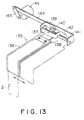
- this shutter mechanism 135 that opens and closes when there is bundling operation.
- this shutter mechanism 135 has a shutter plate 136 has a slightly wider width than the opening width of the opening portion 2 and is formed in the shape of a letter L when seen from the side surface, and a shaft support 137 of the base portion of this shutter plate 136 is inserted into the shaft 138 provided to one side from the leaf paper insertion opening portion 2 of the main apparatus unit 1 and freely slides, and a roller 140 on a shaft 139 that protrudes to the rear from this shaft portion 137 engages with a guide hole 142 that is formed in the horizontal direction in the frame 141 that supports the shaft 138, and the shutter plate 136 is supported so as to be freely movable in the horizontal direction, by the two supports formed by this roller 140 and the shaft 138.
- the end portion of the shaft 139 of the roller 140 is linked to one end of the lever 143, and the other end of this lever 143 is linked to the arm 145 of the rotary solenoid 144, so that the rotation of this rotary solenoid moves the shutter plate 136 via the lever 143 to between the closed position shown by the solid line in FIG. 13, and the open position shown by the dotted line in FIG. 13.
- a positioning plate 153 that is one regulating means for regulating the end opposite the front surface 1a of the main apparatus unit 1, that is, the position of the lower corner that becomes the inner side in the direction of insertion whether the leaf paper is inserted from the top or from the front.
- This positioning plate 153 has the shape of a letter L when seen from the side surface, and regulated the two sides of the lower corner portion of the leaf paper P, with the upright portion 153a being upright so that the leaf paper P contacts it when the detection plate 62 is pressed by the leaf paper P to operate the sensor 68.
- one leaf paper insertion detection means which has sensors 143a, 154a comprising an optical element that detects the upper edge of the leaf paper. That is, sensor comprising the optical element is interrupted by the leaf paper, and when there is no obstruction of the sensor comprising the optical element by the leaf paper, the sensors 154a, 154a detect the upper edge of the leaf paper.
- the head 161 represents an adhesion head, and the head 161 is supported via an arm 160 to a distal end of a freely movable moving platform 159 that engages with roller 158, 158 in the long holes 157 formed so as to rise in an arc from the horizontal direction, in opposing guide rail portions 156 fixed to the main apparatus unit 1, and this head 155 rises along with the tape T that is wound to the leaf paper P and the cut end of the tape T is rubbed from the bottom to the top and is thermally adhered.
- the head 155 has a built-in heater of a known type.
- the cutter 161 is mounted in a direction perpendicular to the distal end of the arm 162, and this arm 162 rotates around the center of a shaft 163 so that the tape T is cut at a required position.
- This is a description of the operation of this embodiment, with reference to FIGS. 14 through 21, and FIG. 24.
- the draw plate 92 of the tape supply portion 90 shown in FIG. 2 is drawn out and the tape reel Tb is placed on the tape loading plate 93, and the tape T that is drawn from the tape reel Tb is taken between the drive roller 95 and the guide roller 96 and presses the draw plate 92.
- this pressing is detected by a sensor (not shown), and the roller 102 is driven, the tape T is taken in and fed.
- the sensor 105 detects the tape T, it feeds tape for a required number of pulses so that it protrudes from the distal end of the tape path.
- the fixed arm 52 and the moving arm 53 of the tape winding means 50 open scissorswise by the action of the cam 82 of the moving member 81 at the position at the distal end of the tape path 101 and tape trails from between both arms (FIG. 14).
- the solenoid 80 of the tape winding means 50 is excited and the moving member 81 is pulled, and the cam 82 escapes so that the moving arm 53 is urged by the spring 78 and closes, to hold the tape T by the fixed arm 52 and the moving arm 53, and then the gear 60 is driven and the engaging gear 59 rotates, the revolving arm 58 is revolved and the arm 51 goes to the standby position shown by B in FIG. 15 while holding the tape T. At this time, the feed of the tape T by the roller 102 places the tape T in the status where the leaf paper is inserted.
- the end portion Tb of the tape T at the standby time is straightened by the straightening arm 110 of the tape straightening plate 106 so that it faces downwards, and is at a position where the insertion of the leaf paper P is not blocked.
- the relay mechanism 35 and the cam member 19 are at the positions shown in FIG. 4, the rollers 18, 28 of the link 24 and the arm 15 are at the lower positions of the cam surfaces 20, 29 and the first hold member 5, second hold member 6 and third holding member 7 are all in the retreated positions.
- the shutter plate 136 of the shutter mechanism 135 of the leaf paper insertion opening portion 2 is in the closed status during the preparation stage until the positioning plate 153 comes to the standby position, and opens at the time when the leaf paper has been received and positioned at the standby position and the receiving preparations are completed.
- the arm 51 presses the distal end portion 112a of the operating lever 112 upwards and the operating lever 122 and the protrusion portion 118 of the leaf paper pressing lever 116 engage so that the leaf paper pressing lever 116 is rocked in the clockwise direction of FIG. 15, and is at a position where it is retreated from the leaf paper insertion opening portion 2.
- the leaf paper that has been stacked of a required number of sheets is inserted from either the front direction (the P 1 direction) or the top direction (the P 2 direction) to the leaf paper insertion opening portion 2 of the main apparatus unit 1 and its distal end is pressed by the leaf paper detection plate 62 so that the shaft 57 retreats to rock the rocker lever 67 and operate the sensor 68.
- the lower edge of the leaf paper P rocks the operating arm 150 and operates that results sensor 152.
- the upper edge of the leaf paper P is detected by the sensors 154a, 154b (with the sensor 154a being in the light receiving status, and the sensor 154b being in the light blocked status).
- the switching status of these sensors 68, 152, 154a, 154b detects that the leaf paper P has been inserted to the bundling position and those detection signals automatically start the bundling operation.
- the automatic start command for bundling operation closes the shutter plate 136 of the shutter mechanism 135 and then when the rocker mechanism (not shown) rocks the relay mechanism 35 in the counterclockwise direction, the cam member 19 moves to the inside and the rollers 18, 28 of the link 24 and the arm 15 are moved in the direction of the outer side by the left and right cam surfaces 20, 29.
- the arm 51 of the tape winding means 50 again revolves and when it does, presses the straightening arm 110 of the tape straightening plate 106 out of the way, and as shown in FIG. 17, passes under the operation lever 112 of the leaf paper pressing mechanism 111 to the side opposite the leaf paper P, and the arm 51 is in contact with the leaf paper surface along the leaf paper P, and the hold of the operation lever 112 is cancelled along with the passage of the arm 51 so that as shown in the figure, the leaf paper pressing lever 116 is rotated counterclockwise by the action of the spring 119, and the pressing portion 114 presses the upper side portion of the leaf paper P so that differences at the top of the leaf paper P are remove (FIG. 18).
- the roller 102 of the tape supply means 100 rotates in reverse to apply a tension to the tape T (FIG. 20) and the head 155 presses the portion that covers the tape T, and at the same time as adhesion start, the cutter 161 lowers to cut the tape T, and the head 155 advances further so that the cut end of the tape T is rubbed upwards and thermally adhered (FIG. 21).
- the cutter 161 and the head 155 return to their original positions, and the moving frame 56 retreats due to the moving mechanism 69 and the arm 51 is removed from the tape adhesion position and along the surface of the leaf paper P in the backwards direction to complete the leaf paper bundling.
- the arm 51 stops at the position shown in FIG.
- the shutter plate 136 again closes and the arm 51 rotates through a required angle from the position shown in FIG. 21 and returns to the tape receive position shown in FIG. 14.
- the arm 51 returns from the forward direction retreat position to the forward direction when there is operation for return to the tape receiving position.
- the roller 102 of the tape supply means 100 rotates forward after it has rotated once in reverse and feeds the tape T, so that as has already been described, is held by the arm 51 and comes to the standby position to enter the standby status shown in FIG. 15.
- the switching switch 165 shown in FIG. 24 switches between an automatic start mode that detects the insertion of the leaf paper P by the sensors 68, 152, 154a, 154b, and a start button mode that starts by the operation of a start button 166 once there is the detection condition by the sensors 68, 152, 154a, 154b.
- the leaf paper pressing lever 116, the arm 51, the bundling mechanism drive portion 167 includes a motor, a solenoid 80 for opening and closing the arm 51, the motor for driving the head 115 and the cutter 161, and a movement solenoid and the like.
- the bundling operation timing detection portion 168 detects the operation timing of the entire bundling apparatus and performs one bundling operation cycle upon the detection conditions and, for example, includes the rotation angle position detection sensor (i.e. a sensor for the detecting the tape receiving position and the standby position B) of the arm 51.
- the control means 169 controls input signal receive of each of the sensors 68, 152, 154a, 154b, 104, 105, the detection portion 168, the start button 166, and the switching switch 165, and the drive of the solenoid 144, the display portion (L, L), the motor M 1 , and the bundling mechanism drive portion 167.
- the following is a description of that bundling operation control.
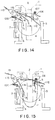
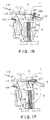
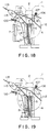
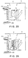
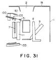
- FIG. 25 through FIG. 31 show another embodiment of the present invention, and those portions that correspond to the embodiment described above are indicated with corresponding numerals and the corresponding descriptions of them are omitted.
- the hold surface 9 moves together with the hold surface 8 and are inclined and rock so that they do not interfere with the rotational motion of the fixed arm 52 and the moving arm 53, and in the previous embodiment there is no hold surface 12, and the leaf paper P is first held when there is the status where the arms 52 and 53 wind the tape T to the leaf paper P and third holding member 7' is in contact with the leaf paper surface (FIG. 27).
- FIG. 25 corresponds to FIG. 15, FIG. 26 to FIG. 18, FIG. 27 to FIG. 19, FIG. 28 to FIG. 20, and FIGS. 29 and 30 correspond to FIG. 21, and FIG. 31 corresponds to FIG. 14.
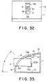
- FIGS. 32 and 33 respectively show an external view of the main apparatus unit 1 and another embodiment relating to the shape of the leaf paper insertion opening portion 2.
- FIG. 32 shows a front view of the main apparatus unit 1
- FIG. 33 is a longitudinal section view of the center position of the leaf paper insertion opening portion 2 shown in FIG. 32.
- those portions that correspond to the embodiment described above with respect to FIG. 1 (B) are indicated with corresponding numerals and the corresponding descriptions of them are omitted.
- the shape of the front cover 1A that configures the main apparatus unit 1 has an inclined surface portion that inclines in the direction towards the rear as a continuation of the curved surface of the front cover 1A.
- the reason for this is that as in the case shown in FIG. 1B, there are instances where there is no clear division of the front surface 1a and the top surface 1b of the main apparatus unit 1.
- the front region of the main apparatus unit of the present invention can have a portion that is higher than the upper region of the main apparatus unit, at an angle of ⁇ which is approximately 45° when expressed with the center point O of the arc in FIG. 33.
- the leaf paper insertion opening portion 2 is formed to open in a arc shape in this embodiment.
- the leaf paper bundling apparatus described in the embodiments is an apparatus that bundles Japanese banknotes (for example ⁇ 10,000, ⁇ 5,000, ⁇ 1,000 notes) for each denomination, and since these banknotes each have the same banknote width (the dimension in the short direction with respect to the long direction of the banknote), the sensors 154a, 154b need only be provided at the top and bottom position but if banknotes of other countries and that have different banknotes widths are to be bundled, it is necessary to provide top and bottom position adjusters for the sensors (154a, 154b) so that the detection of the widths of different denominations can be performed.
- Japanese banknotes for example ⁇ 10,000, ⁇ 5,000, ⁇ 1,000 notes
- a plural number of sensors can be provided for the plural number of banknote denominations.
- the present invention is not limited in application to banknotes, as for example, promissory notes, checks, dockets and other types of leaf paper can also be bundled.
- the apparatus of the present invention is configured from a main unit frame which includes a main unit cover and a front cover that can be opened and closed, and a leaf paper insertion opening portion is formed in the front cover but the configuration need not have the front cover, and the leaf paper insertion opening portion can be formed as a portion of the main unit frame.
- the leaf paper regulating means and the leaf paper insertion detection means are also not limited to the embodiments.
- the bundling position in cases where it is necessary to change the bundling position in accordance with the length dimension (i.e. the long dimension of the leaf paper) and the width dimension (i.e. the short dimension of the leaf paper), it is desirable to have position adjustment of the leaf paper regulating means and the leaf paper insertion detection means in accordance with the type of leaf paper.
- the leaf paper detection plate 62 and the positioning plate 153 can be adjustably moved to the left and right, the sensors 154a, 154b can be adjustably moved up and down and tape supply amount adjustment by the roller 102, 103 can be performed.
- the bundling position is not necessarily limited to a fixed position.
- the first hold surface group of the present invention is equivalent to the hold surface 11 that opposes the hold surface 8, and the lower half portion of the hold surface 9 that opposes the hold surface 12, and the second hold surface group is equivalent to the upper half portion of the hold means 9 that opposes the hold surface 32.
- a separate member can be configured in the region to the top and bottom of the hold means 8,11, so at to have the function of the second hold surface group.
- the intention of "the condition of detection of leaf paper insertion detection means", and “on the basis of detection of leaf paper by said leaf paper insertion detection means” is to include both cases when there is operation by detection output of a leaf paper insertion detection means and operation by both this detection output and the output of a start button.
- a leaf paper bundling apparatus which winds a tape around many leaves of leaf paper which have been stacked, uses a cutter to said wound tape and an thermo-adhesion head to thermally adhere said cut ends and bundles leaf paper
- the insertion of leak paper to the leaf paper bundling apparatus to be performed either in the horizontal direction from the front, or in the vertical direction from the top so that the convenience of use is enhanced, and so that the same position is detected by a regulating means in the case of both directions of insertion and so that no obstruction to bundling operation is presented.
- bundling operation is performed on the conditions that the inserted leaf paper is positioned at a set position and so there is no scattering of the tape winding position with respect to the winding set position, and it is possible to have leaf paper bundles that are uniform and which have been definitely bundled. Furthermore, after the leaf paper has been inserted, the hold means that hold the leaf paper can be hold means provided to perform tape tightening so that the entire mechanism does not become complex, so that space is saved and the apparatus made more compact.
Landscapes
- Engineering & Computer Science (AREA)
- Mechanical Engineering (AREA)
- Basic Packing Technique (AREA)
- Packaging Of Special Articles (AREA)
Description
- The present invention relates to a leaf paper bundling apparatus that winds tape around the periphery of a stack of leaf paper of the same size and shape, which cuts tape ends by a cutter and adheres them by a thermo-adhesion head to bundle leaf paper.
- Bundling apparatus that stacks a required number of banknotes or other leaf paper of the same size and shape, and bundles them by tape has been disclosed in for example, Japanese Patent Application Laid-Open No. 58312/1985. The bundling apparatus disclosed in this publication has a leaf paper insertion opening open on a front surface of a main apparatus unit, and leaf paper is taken in by a rotating wheel of circular shape and that corresponds to a bundling position of leaf paper that is inserted from the opening and positioned. The rotating wheel is provided with a winding member (for example, a roller) for winding tape to the leaf paper that is to be bundled, and the rotation of the rotating wheel winds the bundling tape to the periphery of the leaf paper and also applies a tension to the tape which is then cut by a cutting apparatus, and the cut ends are then adhered by an adhesion head.
- However, with this conventional apparatus, a first problem is there is a rotating wheel provided at the bundling position so as to wind the tape to the bundling position of the leaf paper and so it is not possible for the leaf paper to be inserted from the direction of the line of the axis of the rotating wheel that is, from the front of the apparatus, thereby reducing the convenience of use of the apparatus, and deteriorating the operability.
- A second problem is that the leaf paper is not necessarily positioned accurately to the bundling position when the leaf paper is inserted to the bundling position, and the tape is not accurately wound if the leaf paper moves while the tape is being wound, thereby requiring the leaf paper to be positioned at the bundling position during bundling. The leaf paper can be held by a special hold mechanism prior to bundling operation but this easily interferes with the operation of the mechanism of the entire apparatus becomes complex and the installation space increases.
- Our EP-
A-0 420 560 discloses a leaf paper bundling apparatus forming the pre-characterising portion ofclaim 1. - In a leaf bundling apparatus according to the pre-characterising portion of
claim 1, the slit shaped opening of the insertion opening portion is formed contiguously from a forward portion of the main apparatus unit to an upward portion thereof, and guide edges are formed on the entire peripheral corners of the opening portion. - Providing an opening of this particular configuration enables leaf paper for bundling to be inserted into the apparatus from either the front or the top of the apparatus.
- Under a first embodiment of the present invention, the leaf paper is positioned by the regulating means irrespective of whether the leaf paper is inserted from the front or the top of the leaf paper insertion opening portion of the main apparatus unit, and at a required time after this, and particularly in a second embodiment, when it is detected that the condition of the leaf paper being positioned at the bundling position is satisfied, the tape winding means at the standby position swivels to wind tape around the periphery of the leaf paper and a holding means holds a leaf paper surface portion at a required timing and enables tape to be tightened by a tape tensioning means. In addition, a third embodiment, there is the operation described above as well as a holding means to hold the leaf paper on the condition of the detection of the leak paper insertion detection means.
-
- FIG. 1A is an external view of an embodiment of a basic configuration of a leaf paper bundling apparatus to which the present invention has been applied;
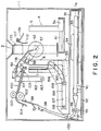
- FIG. 1B is a perspective view of the same embodiment;
- FIG. 2 is a front view of FIG. 1, with the cover removed;
- FIG. 3 is an exploded view showing the leaf paper hold means;
- FIG. 4 is a plan view showing the status prior to operation;
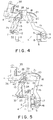
- FIG. 5 is a plan view of the status where the leaf paper is held by the first and second hold members;
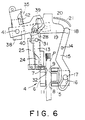
- FIG. 6 is a plan view showing the status where the leaf paper is held by the first, second and third hold members;
- FIG. 7 is a perspective view of the tape winding means;
- FIG. 8 is a perspective view of the arm opening and closing mechanism of FIG. 7;
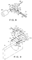
- FIG. 9 is a detailed perspective view of the leaf paper pressing mechanism;
- FIG. 10 is a perspective view of the status where the lid of the tape guide is open;
- FIG. 11 is a partial sectional view showing the status where the tape passes;
- FIG. 12 is a sectional view showing the status where the tape is cut;
- FIG. 13 is a perspective view showing the shutter mechanism of the leaf paper insertion opening portion of the main apparatus unit;
- FIG. 14 is a view describing the operation, and is an outline frontal elevation showing the relationship between each part prior to start of bundling operation;
- FIG. 15 is a view describing the operation, and is an outline frontal elevation showing the status where the arm of the tape winding means is positioned at the standby position;
- FIG. 16 is a view describing the operation, and is an outline frontal elevation showing the status where the leaf paper is inserted and is held by the first and second hold members;
- FIG. 17 is a view describing the operation, and is an outline frontal elevation showing the status where the arm has started to revolve;
- FIG. 18 is a view describing the operation, and is an outline frontal elevation showing the status where the status where the arm has reached a required position with respect to the leaf paper;
- FIG. 19 is a view describing the operation, and is an outline frontal elevation showing the status where the leaf paper is held by the third hold means;
- FIG. 20 is a view describing the operation, and is an outline frontal elevation showing the status where the tape is tensioned;
- FIG. 21 is an outline frontal elevation showing the status where there is the start of thermal adhesion and the tape is cut;
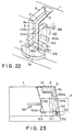
- FIG. 22 is a view describing the leaf paper detection means and the regulating means;
- FIG. 23 is a side elevation describing the leaf paper detection means and the regulating means;
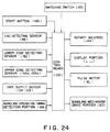
- FIG. 24 is a control block diagram;
- FIG. 25 is a view equivalent to FIG. 15, for another embodiment;
- FIG. 26 is a view equivalent to FIG. 18;
- FIG. 27 is a view equivalent to FIG. 19;
- FIG. 28 is a view equivalent to FIG. 20;
- FIG. 29 is a view equivalent to FIG. 21;
- FIG. 30 is a view equivalent to FIG. 21;
- FIG. 31 is a view equivalent to FIG. 14;
- FIG. 32 is a frontal elevational view of another embodient of the present invention; and
- FIG. 33 is a longitudinal sectional view of FIG. 32.
- The following is a description of preferred embodiments of the present invention, with reference to the accompanying drawings.
- FIG. 1A is an external view of an example of a basic configuration of a leaf paper bundling apparatus to which the present invention has been applied, and in this embodiment, it has a
main apparatus unit 1 having a box shape, and is configured so that an upper portion of a front surface is pivoted so as to form a front cover 1A which is openable, a slit-shaped leaf paperinsertion opening portion 2 is formed from the front surface 1a to the upper surface 1b of the front cover 1A, and an opening having the sectional shape of an inverted letter L is formed so that a plural number of leaves of leaf paper P (such as banknotes) that have been stacked from the leaf paper insertion openingportion 2 are inserted either uprightly and in the horizontal direction from the front of themain apparatus unit 1 as shown by P1, or uprightly and in the vertical direction from the top of themain apparatus unit 1 as shown by P2. - Both of the side edges of the leaf paper insertion opening
portion 2 have formedguide edges guide edges flat guide surfaces surface 3b which is the lower end of the leaf paper insertion openingportion 2. - FIG. 1B shows the
regulating surface 3b that performs more stable regulation of the lower edges of the leaf paper P that extends forwards from the front surface 1a of the front cover 1A in themain apparatus unit 1, and the leaf paper insertion path of themain apparatus unit 1 is provided with one portion of a regulating means that positions the leaf paper P at the bundling position, and a leaf paper insertion detection means that detects that the leaf paper P has been positioned at the bundling position. - To positions on both sides and upwards from both sides of the leaf paper insertion opening
portion 2 are provided the display portions L, L and these display portions L,L display the following operating statuses, for example. - Steady green lamp: Indicates standby, leaf paper insertion possible and bundling possible status.
- Slowly blinking green lamp: Indicates operation of bundling mechanism.
- Quickly blinking green lamp: Indicates completion of bundling and presence of leaf paper inside. When bundled leaf paper is removed, blinking speed of lamp changes from fast to slow, the bundling mechanism returns to a set position and lamp changes to steady green after return of the bundling mechanism to this set position.
- Steady red lamp: Indicates an error or an operation failure.
- Alternating red and green blinking lamps: Indicates that little paper tape remains.
- The leaf paper holding means 4 are arranged on both sides of the insertion path for the leaf paper P that is inserted from the leaf paper
insertion opening portion 2, and holds from both the left and right sides of the leaf paper P that has been inserted from the leaf paperinsertion opening portion 2 and which is at a set position. One example of this is shown in FIGS. 2 through 6. - More specifically, as shown by the exploded drawing of FIG. 3 and the plan views of FIGS 4. through 6 that show the operating status, the configuration has a
first hold member 5 that is positioned at one side of the leaf paper P that is inserted to the bundling position, asecond hold member 6 and athird holding member 7 positioned on the other side. - The
first hold member 5 has a length that covers the short direction of the leaf paper P that have been inserted into the bundling position, that is, the two holdingsurfaces base portion 5a is supported so as to be freely movable in the direction of the paper surface of the leaf paper P and along the guide rails 10, 10. - The
second hold member 6 has substantially the same height as the holdingsurface 8 that corresponds to the holdingsurface 8 of the front side of thefirst hold member 5, that is, ahold surface 11 that has a length that is longer than the width of the short direction of the leaf paper P, and a holding surface that has a low height and that corresponds to the downwards portion of the holdingsurface 9 on the inner side of thefirst hold member 5, and the third holdingmember 7 is formed so as to rise to one end of alever 13 so that leaf paper that is higher than a holdingsurface 12 of thesecond hold member 6 is placed at the position of the holding height. - When the leaf paper P is held by the
first hold member 5 and thesecond hold member 6, it is held across its full width and so it is not possible for the ends of the leaf paper to be bent when the tape is tightened in the course of tape winding. - In FIG. 3, the operation mechanisms of each of the holding members are shown by the case when a link mechanism is used. More specifically, the
first hold member 5 is formed so that the middle portion has along hole 16 at one end of anarm 15 supported so as to be freely rotatable inside the horizontal plane by theshaft 14 on the side of themain apparatus unit 1, thislong hole 16 is linked through engaging with anupright pin 17 in thebase portion 5a, aroller 18 pivoted to the base end of thearm 15 comes into contact with acam surface 20 on the right side ofcam member 19 that moves towards the front and back of the main apparatus unit 1 (as shown by the arrow in FIG. 3), and thisroller 18 moves in accordance with thecap surface 20 by theguide member 21 that has a similar shape to thecam surface 20. - The
second hold member 6 is linked by thepins parallel links shafts main apparatus unit 1, and aspring 30 brings aroller 28 at the base end of one of thelinks 24 into contact with acam surface 29 on the left side of thecam member 19. Then, theshaft 22 of thislink 24 engages with and is supported by ashaft hole 31 in the middle portion of thelevel 13 that has the third holdingmember 7, and when thelever 13 turns around thisshaft 22, the holdingsurface 32 of the third holdingmember 7 supports the leaf paper P along with the upper half of the holdingsurface 9 on the inside of thefirst hold member 5. The numeral 33 is a spring for the return of thelever 13. - To the base end of the
lever 13 is pivoted aroller 34 and thisroller 34 engages with along hole 39 of arelay mechanism 35 to be described later. Thisrelay mechanism 35 has adrive portion 40 that is rocked in the direction shown by the arrow, and has along hole 36 at one end linked by apin 37 in the middle of a lower surface of acam member 19, and other other end having amember 38 that is bent in the shape of a reversed letter C when seen from the side and which is the shape of a letter L when seen in plan, and one end of which has thelong hole 39 having the shape of a crank handle, and the other end of which has adrive portion 40a that is rocked in the direction shown by the arrow, by a drive mechanism comprising a cam not shown in the figure. The middle portion is configured from amember 40 that is bent in the shape of a reversed letter C when seen from the side, and thesemembers main apparatus unit 1 by the sharedpivot shaft 41, and theroller 34 of thelever 13 engages with thelong hole 39 that has the shape of a crank handle. - Accordingly, the rocker mechanism (not shown) operates the
drive portion 40a and when themember 40 rocks about theshaft 41 and in the counterclockwise direction in FIG. 3, themember 38 that is joined to thetension spring 42 also rocks in the same direction, and thecam member 19 that is linked to themember 38 by thepin 37 moves back and forth. Along with this, because of the long hole that has the shape of a crankhandle, thelever 13 rotates in the counterclockwise direction in FIG. 3 and about theshaft 22, via theroller 34 of thelever 13, and that third holdingmember 7 is delayed by thefirst hold member 5 and thesecond hold member 6 and advances to the leaf paper hold position. At this time, even if thefirst hold member 5 and thesecond hold member 6 hold leaf paper that has thick leaves and the retreat of thecam member 19 stops midway, thetension spring 42 that links themember 38 and thedrive portion 40 elongates and only thedrive portion 40 continues to rotate, and as described before, the third holdingmember 7 advances to the leaf paper bundling position via thelever 13. (See FIG. 6.) - The cam surfaces 20, 29 of the left and right side surfaces of the
cam member 19 have inclined surfaces that have a wider width on the side of leaf paper insertion, and when thecam member 19 moves towards the back, theroller link 24 and thearm 15 are pressed to the left and right directions and thefirst hold member 5 and thesecond hold member 6 move to approach each other. - Then, the
tape winding means 50 is shown in FIG. 7, and as shown in FIG. 8 for the opening and closing mechanism of thearm 51, has a movingarm 53 and a fixedarm 52 at holds in the vicinity of the leading end of the tape T, and thisarm 51 can go around the periphery of the leaf paper P at a bundling position and so as to describe a circular path shown by the letter A in the figure. - The fixed
arm 52 is fixedly provided in the direction parallel to the axis of theshaft 57, at the distal end of the revolvingarm 58 that can freely revolve by theshaft 57 passing through and supported by themachine frame 56 and with one end supported so as to be movable along its axis and so that its central portion is supported by and can slide in the same direction along theguide rods machine frame 54, and on theshaft 57 of the portion through which the movingframe 56 passes is fixed agear 59 with short teeth, and thisgear 59 always engages with thegear 60 with long teeth and which is axially mounted in themachine frame 54. Thisgear 60 is given a rotation via abelt 61 from a motor (not shown). - A
detection plate 62 is fixed to the end portion of the front side of theshaft 57, as one element of a configuration of a leaf paper insertion detection means that detects the insertion of leaf paper P to a set position, and between the inside end of theshaft 57 and the fixedmember 63 of the side of themachine frame 54 there is acompression spring 64 that pushes theshaft 57 to the outer front side. In the vicinity of the inside end of thisshaft 57, apulley 65 is fixed and the groove of thispulley 65 engages with one end of the rocking lever that rocks around theshaft 66, and the other end of this rocking lever is linked to asensor 68 so that the rockinglever 67 rocks when pressed to the inside, and leaf paper trailing end detection signals are obtained via asensor 68. - The moving
mechanism 69 of the movingframe 56 is configured from an L-shapedlever 71 that has the bend portion linked to the movingframe 56 and pivoted by ashaft 70 on the side of the machine frame, and a lever 73 that has a bend linked to one end oflever 71 and which is pivoted by theshaft 72 on the side of themain apparatus unit 1, andcam followers lever 71 is pushed and pulled. - The moving
arm 53 is configured so that the base portion opens and closes scissorswise with respect to the fixedarm 52 that is supported so as to be freely rotatably by ashaft 77 to the revolvingarm 58, and is urged by aspring 78 between the vicinity of the base end and the revolvingarm 58 so that it is always urged in the closed direction. In addition, when acam follower 79 strikes thecam 82 on the side surface of the movingportion 81 that retreats by the action of thesolenoid 80 as shown in FIG. 8, the movingarm 53 is separated from the fixedarm 52, and this movingmember 81 has apin 83 fixed in it, inserted into the long guide hole that is angled when seen from the plane of theguide member 84 and thecam 82 is pulled in when the movingmember 81 is drawn in by the excitation of thesolenoid 80, and when the excitation is cancelled, thecam 82 is pulled by thespring 86 and advances to the position of thecam follower 79. - A
tape supply portion 90 has atape loading plate 93 on which is placed a tape reel Ta on thedraw plate 92 provided so as to be freely drawable from the lower portion of thebase plate 91 on which are arranged the leaf paper holding means 4 of themain apparatus unit 1 as shown in FIG. 2, and the tape T is drawn from the tape reel Ta that is mounted so that its center hole engages with acylindrical portion 94 at the center of thetape loading plate 93, and is led via adrive roller 95, aguide roller 96, atape lead path 97 and tape guides 98, 99, to a tape supply means 100. This tape supply means 100 also functions as the tape tensioning means and so has a flat tape path 101 that guides the tape T, and is provided with top andbottom rollers rollers 102 is rotatably driven by a pulse motor M1 (shown in FIGS. 2 and 4) that feeds the tape T by the necessary amount, and rotates in reverse at a required time to provide a tension to the tape T and tighten it. In front of the positions of therollers - A
tape straightening plate 106 is provided in the vicinity of thearm 51 that is at the standby position (the position B in FIG. 15) where thearm 51 of thetape winding means 50. Thistape straightening plate 106 has its end portions substantially in the shape of a letter L, and the corner portion is pivoted to ashaft 107, and thisshaft 107 is supported by a shaft received 108 on the side of themain apparatus unit 1 so that it can rotate, and areturn spring 109 mounted between theshaft receiver 108 and thetape straightening plate 106 causes thetape straightening plate 106 to be positioned at a set position. This set position of thetape straightening plate 106 is a position that is slightly separate from the insertion path of the leaf paper P so that the straighteningarm 110 on one side of thetape straightening plate 106 does not interfere with the leaf paper P that is positioned at the bundling position (See FIG. 2) and the distal end of the tape T that is held by thearm 51 is straightened by the straighteningarm 110 so that it does not protrude to the insertion path of the leaf paper P. Then, when thearm 51 revolves, the straighteningarm 110 strikes thearm 51 and presses it, and thetape straightening plate 106 resists the force of thespring 109 to rotate to allow the passage of thearm 51, and after it has passed, the action of the return spring returns it to the set position. - Slightly to the inside side from the position where the
tape straightening plate 106 is provided, is provided a leaf paper pressing mechanism 111 according to the present invention, and so as to prevent slippage of the leaf paper on the side of the inner insertion end of the leaf paper P. As shown in FIG. 9, this leaf paper pressing mechanism 111 has adistal end portion 112a enter the revolving path A of thearm 51 of thetape winding means 50 and the middle portion is operated by the operatinglever 112 supported to the side of themain apparatus unit 1 by theshaft 113, and has a leafpaper pressing lever 116 that is axially supported to the side of themain apparatus unit 1 by ashaft 115 while apressing portion 114 at the distal end can contact an upper side portion in the vicinity of the inner end of the leaf paper P placed at the bundling position. The engagingportion 117 of the rear end side portion of the operatinglever 112 engages with the protrudingportion 118 that protrudes to the side portion of thepressing lever 116, and is pulled by aspring 119 that is stretched between thepressing lever 116 and themain apparatus unit 1 so that the protrudingportion 118 is always in contact with the engaging portion, and when itsdistal end portion 112a is raised by thearm 51, thepressing portion 114 of thepressing lever 116 rotates in the direction so as to separate it from the paper surface of the leaf paper P. - The
tape guide 98 that leads the tape T that is fed from thetape supply portion 90, to the tape supply means 100 is provided with a tape path member 120 that has a sectional shape of a reversed letter C as shown in FIG. 10, and alid member 123 that is pivoted by ashaft 122 between theside wall portions lid member 123 are provided upright shaft supports 124, 124 on the outer surface side on both sides of thelid member 123. Apin 126 is freely inserted into and supported byholes shaft support portion lid member 123, and thispin 126 is urged in the direction of the distal end of thelid member 123 bysprings pin 126, and the engagement of thepin 126 to theengagement portions lid member 123 in the closed status. -
Screws cutter member 130 comprising a flexible material to a fixedmember 129 at a position so that it does not obstruct the advancing of the tap T from the tape advancing end of the tape path member 120, and the free end of thiscutter portion 130 enters into the tape path member 120 so that there is always gap between thecutter 130 and the path surface 131 of the tape path member 120 and so that there is no obstruction to the passage of the tape T. - To the base end of the
lid member 123 is provided acap portion 132 that comes into contact with the side of the back surface of thecutter member 130. Thiscam portion 132 has acam surface 134 of large diameter and acam surface 133 of small diameter with respect to thepivot shaft 122 of thelid member 123 shown in FIGS. 11 and 12, and the small-diameter cam surface 133 is placed along thecutter member 130 when thelid member 123 is closed, and when thelid member 123 is open, the large-diameter cam surface 134 comes into contact with thecutter member 130 and gradually presses thecutter member 130 to the side of thepath surface 131, and finally, the blade portion 130a at the distal end of thecutter member 130 is pressed into contact with the tape T on thepath surface 131. Accordingly, when thelid member 123 is opened and the pulling and tensioning of the tape T from above the tape path member 120 cuts the tape T by the blade portion 130a at the distal end of thecutter member 130, cuts the end of the tape and jamming of the tap is promptly eliminated. - That portion of the leaf paper
insertion opening portion 2 of themain apparatus unit 1 that opens to the upper surface 1b is provided ashutter mechanism 135 that opens and closes when there is bundling operation. As seen in FIG 13, on the inner side of the leaf paper insertion opening portion, thisshutter mechanism 135 has ashutter plate 136 has a slightly wider width than the opening width of theopening portion 2 and is formed in the shape of a letter L when seen from the side surface, and ashaft support 137 of the base portion of thisshutter plate 136 is inserted into theshaft 138 provided to one side from the leaf paperinsertion opening portion 2 of themain apparatus unit 1 and freely slides, and aroller 140 on ashaft 139 that protrudes to the rear from thisshaft portion 137 engages with aguide hole 142 that is formed in the horizontal direction in theframe 141 that supports theshaft 138, and theshutter plate 136 is supported so as to be freely movable in the horizontal direction, by the two supports formed by thisroller 140 and theshaft 138. The end portion of theshaft 139 of theroller 140 is linked to one end of thelever 143, and the other end of thislever 143 is linked to thearm 145 of therotary solenoid 144, so that the rotation of this rotary solenoid moves theshutter plate 136 via thelever 143 to between the closed position shown by the solid line in FIG. 13, and the open position shown by the dotted line in FIG. 13. - As shown in FIG. 22 and FIG. 23, to the inside of the regulating
surface 3b of the leaf paperinsertion opening portion 2 of themain apparatus unit 1, there is anoperating arm 150 supported by ashaft 151 and that is pressed by the lower edge of the leaf paper P irrespective of whether it was inserted from the front direction or the top direction into the leaf paperinsertion opening portion 2, and normally, a spring (not shown) positions the distal end above the regulatingsurface 3b so that when it is pressed by the lower edge of the leaf paper P, it becomes the horizontal status in substantially the same plane as the regulatingsurface 3b so as to cause thesensor 152 to operate. This is the configuration of the leaf paper insertion detection means that functions as a leaf paper lower edge detection sensor. - In addition, there is provided a
positioning plate 153 that is one regulating means for regulating the end opposite the front surface 1a of themain apparatus unit 1, that is, the position of the lower corner that becomes the inner side in the direction of insertion whether the leaf paper is inserted from the top or from the front. Thispositioning plate 153 has the shape of a letter L when seen from the side surface, and regulated the two sides of the lower corner portion of the leaf paper P, with theupright portion 153a being upright so that the leaf paper P contacts it when thedetection plate 62 is pressed by the leaf paper P to operate thesensor 68. - To the guide surfaces 3a, 3a of the side of the front side 1a of the leaf paper
insertion opening portion 2 is configured one leaf paper insertion detection means, which hassensors 143a, 154a comprising an optical element that detects the upper edge of the leaf paper. That is, sensor comprising the optical element is interrupted by the leaf paper, and when there is no obstruction of the sensor comprising the optical element by the leaf paper, thesensors head 161 is supported via anarm 160 to a distal end of a freely movable movingplatform 159 that engages withroller long holes 157 formed so as to rise in an arc from the horizontal direction, in opposingguide rail portions 156 fixed to themain apparatus unit 1, and thishead 155 rises along with the tape T that is wound to the leaf paper P and the cut end of the tape T is rubbed from the bottom to the top and is thermally adhered. Thehead 155 has a built-in heater of a known type. - Details of the
cutter 161 are not shown in the figure but it is mounted in a direction perpendicular to the distal end of thearm 162, and thisarm 162 rotates around the center of ashaft 163 so that the tape T is cut at a required position.
The following is a description of the operation of this embodiment, with reference to FIGS. 14 through 21, and FIG. 24. - The
draw plate 92 of thetape supply portion 90 shown in FIG. 2 is drawn out and the tape reel Tb is placed on thetape loading plate 93, and the tape T that is drawn from the tape reel Tb is taken between thedrive roller 95 and theguide roller 96 and presses thedraw plate 92. When this pressing is detected by a sensor (not shown), and theroller 102 is driven, the tape T is taken in and fed. Then, after thesensor 105 detects the tape T, it feeds tape for a required number of pulses so that it protrudes from the distal end of the tape path. At this time, the fixedarm 52 and the movingarm 53 of the tape winding means 50 open scissorswise by the action of thecam 82 of the movingmember 81 at the position at the distal end of the tape path 101 and tape trails from between both arms (FIG. 14). - After this, the
solenoid 80 of thetape winding means 50 is excited and the movingmember 81 is pulled, and thecam 82 escapes so that the movingarm 53 is urged by thespring 78 and closes, to hold the tape T by the fixedarm 52 and the movingarm 53, and then thegear 60 is driven and theengaging gear 59 rotates, the revolvingarm 58 is revolved and thearm 51 goes to the standby position shown by B in FIG. 15 while holding the tape T. At this time, the feed of the tape T by theroller 102 places the tape T in the status where the leaf paper is inserted. - The end portion Tb of the tape T at the standby time is straightened by the straightening
arm 110 of thetape straightening plate 106 so that it faces downwards, and is at a position where the insertion of the leaf paper P is not blocked. - At this time, the
relay mechanism 35 and thecam member 19 are at the positions shown in FIG. 4, therollers link 24 and thearm 15 are at the lower positions of the cam surfaces 20, 29 and thefirst hold member 5,second hold member 6 and third holdingmember 7 are all in the retreated positions. In addition, theshutter plate 136 of theshutter mechanism 135 of the leaf paperinsertion opening portion 2 is in the closed status during the preparation stage until thepositioning plate 153 comes to the standby position, and opens at the time when the leaf paper has been received and positioned at the standby position and the receiving preparations are completed. - In addition, when the
arm 51 is positioned at the standby position, thearm 51 presses thedistal end portion 112a of the operatinglever 112 upwards and the operatinglever 122 and theprotrusion portion 118 of the leafpaper pressing lever 116 engage so that the leafpaper pressing lever 116 is rocked in the clockwise direction of FIG. 15, and is at a position where it is retreated from the leaf paperinsertion opening portion 2. Here, the leaf paper that has been stacked of a required number of sheets is inserted from either the front direction (the P1 direction) or the top direction (the P2 direction) to the leaf paperinsertion opening portion 2 of themain apparatus unit 1 and its distal end is pressed by the leafpaper detection plate 62 so that theshaft 57 retreats to rock therocker lever 67 and operate thesensor 68. In addition, the lower edge of the leaf paper P rocks theoperating arm 150 and operates thatresults sensor 152. Then, the upper edge of the leaf paper P is detected by thesensors sensor 154a being in the light receiving status, and thesensor 154b being in the light blocked status). The switching status of thesesensors - The automatic start command for bundling operation closes the
shutter plate 136 of theshutter mechanism 135 and then when the rocker mechanism (not shown) rocks therelay mechanism 35 in the counterclockwise direction, thecam member 19 moves to the inside and therollers link 24 and thearm 15 are moved in the direction of the outer side by the left and right cam surfaces 20, 29. - The movement of the
cam member 19 to the inside moves both thefirst hold member 5 and thesecond hold member 6 in the directions whereby they contact, and this movement causes the hold surfaces 8, 9, 11, 12 to hold both sides of the leaf paper P (FIGS. 5 and 16). - After this, the
arm 51 of the tape winding means 50 again revolves and when it does, presses the straighteningarm 110 of thetape straightening plate 106 out of the way, and as shown in FIG. 17, passes under theoperation lever 112 of the leaf paper pressing mechanism 111 to the side opposite the leaf paper P, and thearm 51 is in contact with the leaf paper surface along the leaf paper P, and the hold of theoperation lever 112 is cancelled along with the passage of thearm 51 so that as shown in the figure, the leafpaper pressing lever 116 is rotated counterclockwise by the action of thespring 119, and thepressing portion 114 presses the upper side portion of the leaf paper P so that differences at the top of the leaf paper P are remove (FIG. 18). - Then, the
roller 34 of thelever 13 rotates thelever 13 by the long crankhandle-shapedhole 39 of thedrive portion 40 of therelay mechanism 35 and the third holdingmember 7 is brought into contact with the leaf paper P (See FIG. 6). By this, each of the hold surfaces 8, 9, 11, 12, 32 of thefirst hold member 5,second hold member 6 and third holdingmember 7 hold both side surfaces of the leaf paper P (FIG. 19). - Then, the
roller 102 of the tape supply means 100 rotates in reverse to apply a tension to the tape T (FIG. 20) and thehead 155 presses the portion that covers the tape T, and at the same time as adhesion start, thecutter 161 lowers to cut the tape T, and thehead 155 advances further so that the cut end of the tape T is rubbed upwards and thermally adhered (FIG. 21).
After this, when thecutter 161 and thehead 155 return to their original positions, and the movingframe 56 retreats due to the movingmechanism 69 and thearm 51 is removed from the tape adhesion position and along the surface of the leaf paper P in the backwards direction to complete the leaf paper bundling. Moreover, thearm 51 stops at the position shown in FIG. 21 in the status where it is removed to the rear. Then, thecam member 19 also returns to its initial position and each of thefirst hold member 5,second hold member 6 and third holdingmember 7 open to their initial positions and the hold of the leaf paper P is cancelled, theshutter plate 136 opens and it is possible for the bundled leaf paper to be removed. - When the bundled leaf paper P is removed, the
shutter plate 136 again closes and thearm 51 rotates through a required angle from the position shown in FIG. 21 and returns to the tape receive position shown in FIG. 14. Thearm 51 returns from the forward direction retreat position to the forward direction when there is operation for return to the tape receiving position. Then, theroller 102 of the tape supply means 100 rotates forward after it has rotated once in reverse and feeds the tape T, so that as has already been described, is held by thearm 51 and comes to the standby position to enter the standby status shown in FIG. 15. - The switching
switch 165 shown in FIG. 24 switches between an automatic start mode that detects the insertion of the leaf paper P by thesensors start button 166 once there is the detection condition by thesensors - In addition, in FIG. 24, as well as the holding
members paper pressing lever 116, thearm 51, the bundlingmechanism drive portion 167 includes a motor, asolenoid 80 for opening and closing thearm 51, the motor for driving thehead 115 and thecutter 161, and a movement solenoid and the like. - In addition, the bundling operation
timing detection portion 168 detects the operation timing of the entire bundling apparatus and performs one bundling operation cycle upon the detection conditions and, for example, includes the rotation angle position detection sensor (i.e. a sensor for the detecting the tape receiving position and the standby position B) of thearm 51. The control means 169 controls input signal receive of each of thesensors detection portion 168, thestart button 166, and the switchingswitch 165, and the drive of thesolenoid 144, the display portion (L, L), the motor M1, and the bundlingmechanism drive portion 167. The following is a description of that bundling operation control. - FIG. 25 through FIG. 31 show another embodiment of the present invention, and those portions that correspond to the embodiment described above are indicated with corresponding numerals and the corresponding descriptions of them are omitted. The structural differences are that in the previous embodiment, the
hold surface 9 moves together with thehold surface 8 and are inclined and rock so that they do not interfere with the rotational motion of the fixedarm 52 and the movingarm 53, and in the previous embodiment there is nohold surface 12, and the leaf paper P is first held when there is the status where thearms - FIGS. 32 and 33 respectively show an external view of the
main apparatus unit 1 and another embodiment relating to the shape of the leaf paperinsertion opening portion 2. In particular, FIG. 32 shows a front view of themain apparatus unit 1 and FIG. 33 is a longitudinal section view of the center position of the leaf paperinsertion opening portion 2 shown in FIG. 32. In this embodiment, those portions that correspond to the embodiment described above with respect to FIG. 1 (B) are indicated with corresponding numerals and the corresponding descriptions of them are omitted. - In this embodiment, the shape of the front cover 1A that configures the
main apparatus unit 1 has an inclined surface portion that inclines in the direction towards the rear as a continuation of the curved surface of the front cover 1A. The reason for this is that as in the case shown in FIG. 1B, there are instances where there is no clear division of the front surface 1a and the top surface 1b of themain apparatus unit 1. In this example, the front region of the main apparatus unit of the present invention can have a portion that is higher than the upper region of the main apparatus unit, at an angle of θ which is approximately 45° when expressed with the center point O of the arc in FIG. 33. In addition, the leaf paperinsertion opening portion 2 is formed to open in a arc shape in this embodiment. - The present invention is however not limited to the embodiments described above, and in particular, the leaf paper bundling apparatus described in the embodiments is an apparatus that bundles Japanese banknotes (for example ¥10,000, ¥5,000, ¥1,000 notes) for each denomination, and since these banknotes each have the same banknote width (the dimension in the short direction with respect to the long direction of the banknote), the
sensors - In the embodiments, the apparatus of the present invention is configured from a main unit frame which includes a main unit cover and a front cover that can be opened and closed, and a leaf paper insertion opening portion is formed in the front cover but the configuration need not have the front cover, and the leaf paper insertion opening portion can be formed as a portion of the main unit frame. Furthermore, the leaf paper regulating means and the leaf paper insertion detection means are also not limited to the embodiments.
- Also, in cases where it is necessary to change the bundling position in accordance with the length dimension (i.e. the long dimension of the leaf paper) and the width dimension (i.e. the short dimension of the leaf paper), it is desirable to have position adjustment of the leaf paper regulating means and the leaf paper insertion detection means in accordance with the type of leaf paper. For example, in FIG. 23, the leaf
paper detection plate 62 and thepositioning plate 153 can be adjustably moved to the left and right, thesensors roller - Also, with respect to the hold means, the first hold surface group of the present invention is equivalent to the
hold surface 11 that opposes thehold surface 8, and the lower half portion of thehold surface 9 that opposes thehold surface 12, and the second hold surface group is equivalent to the upper half portion of the hold means 9 that opposes thehold surface 32. However, without being limited to the embodiments, a separate member can be configured in the region to the top and bottom of the hold means 8,11, so at to have the function of the second hold surface group. - In addition, the intention of "the condition of detection of leaf paper insertion detection means", and "on the basis of detection of leaf paper by said leaf paper insertion detection means" is to include both cases when there is operation by detection output of a leaf paper insertion detection means and operation by both this detection output and the output of a start button.
- According to the present invention, in a leaf paper bundling apparatus which winds a tape around many leaves of leaf paper which have been stacked, uses a cutter to said wound tape and an thermo-adhesion head to thermally adhere said cut ends and bundles leaf paper, it is possible for the insertion of leak paper to the leaf paper bundling apparatus to be performed either in the horizontal direction from the front, or in the vertical direction from the top so that the convenience of use is enhanced, and so that the same position is detected by a regulating means in the case of both directions of insertion and so that no obstruction to bundling operation is presented. According to the present invention, bundling operation is performed on the conditions that the inserted leaf paper is positioned at a set position and so there is no scattering of the tape winding position with respect to the winding set position, and it is possible to have leaf paper bundles that are uniform and which have been definitely bundled. Furthermore, after the leaf paper has been inserted, the hold means that hold the leaf paper can be hold means provided to perform tape tightening so that the entire mechanism does not become complex, so that space is saved and the apparatus made more compact.
Claims (4)
- Leaf paper bundling apparatus which winds a tape around many leaves of leaf paper which have been stacked, uses a cutter to cut the wound tape and a thermo-adhesion head to thermally adhere the cut ends and bundles the leaf paper, said leaf paper bundling apparatus comprising:a leaf paper insertion opening portion (2) having a slit shaped opening and into which leaf papers (P) to be bundled are inserted uprightly from a front surface (1a) or an upper surface (1b) of said main apparatus unit (1);a leaf paper regulation device (3a,3b,153) which guides the leaf papers (P) which are inserted uprightly into said insertion opening (2) from an upward or forward direction of said insertion opening (2) and positions the leaf papers (P) to be inserted at a bundling position by providing positioning members (3a,3b,153) on a bottom surface and on a closed end surface of said insertion opening (2), respectively;a tape supply device (100) which supplies the tape (T) to be wound around a periphery of the leaf paper (P), applies a tension to wound tape (T) and tighten said tape (T) wound around the periphery of leaf paper (P);a tape winding device (50) which has an arm (51) which can hold an end of the tape (T) fed from said tape supply device (100) and which can swivel to wind the tape around from a standby position and around leaf paper (P); anda leaf paper holding device (4) provided so as to tighten the tape (T) wound around the periphery of the leaf paper (P) and which holds a paper surface of the leaf paper in the vicinity of portions on both sides in the direction of the width of the tape wound around a periphery of the leaf paper,characterised in that the slit shaped opening of the insertion opening portion is formed contiguously from the forward portion of the main apparatus unit (1) to an upward portion thereof, and guide edges (3) are formed on entire peripheral corners of the opening portion (2).
- The leaf paper bundling apparatus according to claim 1, wherein the arm (51) when in an upwards position opposite a mounting position of the tape supply device (100) in a standby position, is adapted to swivel from said standby position upon the condition of detection of leaf paper insertion detection device and is adapted to wind the tape (T) around the leaf paper (P).
- The leaf paper bundling apparatus according to claim 1, or claim 2, wherein said leaf paper holding device (4) has a plural number of holding members (6,7) which holds in the vicinity of portions on both sides in the direction of the width of the tape wound (T) whereby at least a portion of the holding members (6,7) holds the leaf paper (P) on the basis of detection of the leaf paper by said leaf paper insertion detection device (62).
- The leaf paper bundling apparatus according to any preceding claim, wherein said leaf paper holding device (4) has a first holding surface group which holds the leaf paper on the basis of detection of the leaf paper by said leaf paper insertion detection device (62), and a second holding surface group which holds the leaf paper after contact operation to the leaf paper surface when the tape is wound by said tape winding device (50).
Applications Claiming Priority (4)
| Application Number | Priority Date | Filing Date | Title |
|---|---|---|---|
| JP88377/91U | 1991-10-28 | ||
| JP1991088377U JP2568065Y2 (en) | 1991-10-28 | 1991-10-28 | Paper binding device |
| JP107556/91U | 1991-12-26 | ||
| JP10755691U JP2550417Y2 (en) | 1991-12-26 | 1991-12-26 | Paper binding device |
Publications (3)
| Publication Number | Publication Date |
|---|---|
| EP0540134A2 EP0540134A2 (en) | 1993-05-05 |
| EP0540134A3 EP0540134A3 (en) | 1993-10-27 |
| EP0540134B1 true EP0540134B1 (en) | 1996-11-27 |
Family
ID=26429768
Family Applications (1)
| Application Number | Title | Priority Date | Filing Date |
|---|---|---|---|
| EP92301625A Expired - Lifetime EP0540134B1 (en) | 1991-10-28 | 1992-02-26 | Leaf paper bundling apparatus |
Country Status (6)
| Country | Link |
|---|---|
| US (1) | US5233816A (en) |
| EP (1) | EP0540134B1 (en) |
| KR (1) | KR960000105B1 (en) |
| CA (1) | CA2062020C (en) |
| DE (1) | DE69215488T2 (en) |
| ES (1) | ES2096713T3 (en) |
Families Citing this family (9)
| Publication number | Priority date | Publication date | Assignee | Title |
|---|---|---|---|---|
| GB9907736D0 (en) | 1999-04-01 | 1999-05-26 | Rue De Int Ltd | Banding apparatus and method |
| JP4939759B2 (en) * | 2004-03-19 | 2012-05-30 | 株式会社東芝 | Paper sheet processing equipment |
| US8567156B2 (en) * | 2009-06-15 | 2013-10-29 | Kabushiki Kaisha Toshiba | Paper sheet processing system |
| US9375074B2 (en) * | 2010-12-01 | 2016-06-28 | Darrell A. Moreau | Clip for attaching articles together |
| CN103274071B (en) * | 2013-05-28 | 2015-05-13 | 广州广电运通金融电子股份有限公司 | Bundling medium clamping mechanism and paper money bundling machine with same |
| JP6162524B2 (en) * | 2013-07-31 | 2017-07-12 | グローリー株式会社 | Paper sheet bundling device |
| WO2015164849A1 (en) | 2014-04-26 | 2015-10-29 | Arthropod Biosciences, Llc | Insect trap device and method of using |
| CN106494661B (en) * | 2016-12-09 | 2023-03-03 | 重庆锦沙沣包装有限公司 | Wrapping bag finishing device |
| CN110033691A (en) * | 2019-04-23 | 2019-07-19 | 长沙宁湖机械设备有限公司 | For showing the teaching aid of cam channel combination |
Family Cites Families (8)
| Publication number | Priority date | Publication date | Assignee | Title |
|---|---|---|---|---|
| US3729886A (en) * | 1971-05-17 | 1973-05-01 | Leroy E Olsen And Sy Patrickus | Method and apparatus for banding articles |
| JPS526298A (en) * | 1975-07-03 | 1977-01-18 | Toshiba Seiki Kk | Automatic string hanger for twofold rolled and one-fold rolled binding |
| JPS5644991A (en) * | 1979-09-21 | 1981-04-24 | Tokyo Shibaura Electric Co | Document handling machine |
| JPS5813407B2 (en) * | 1980-06-18 | 1983-03-14 | 武蔵株式会社 | Paper sheet alignment and banding device |
| JPS58171315A (en) * | 1982-03-31 | 1983-10-08 | 株式会社東芝 | Bundling device |
| JPS58203809A (en) * | 1982-05-13 | 1983-11-28 | 株式会社東芝 | Bundling device |
| NL8500050A (en) * | 1985-01-09 | 1986-08-01 | Nicolaas Van Rosendal | DEVICE FOR APPLYING A CLOSING STRIP AND A CASSETTE FOR THAT. |
| US5126002A (en) * | 1989-09-29 | 1992-06-30 | Glory Kogyo Kabushiki Kaisha | Leaf paper bundling apparatus |
-
1992
- 1992-02-25 US US07/839,895 patent/US5233816A/en not_active Expired - Lifetime
- 1992-02-26 ES ES92301625T patent/ES2096713T3/en not_active Expired - Lifetime
- 1992-02-26 EP EP92301625A patent/EP0540134B1/en not_active Expired - Lifetime
- 1992-02-26 DE DE69215488T patent/DE69215488T2/en not_active Expired - Fee Related
- 1992-02-27 CA CA002062020A patent/CA2062020C/en not_active Expired - Fee Related
- 1992-02-29 KR KR1019920003341A patent/KR960000105B1/en not_active Expired - Fee Related
Also Published As
| Publication number | Publication date |
|---|---|
| ES2096713T3 (en) | 1997-03-16 |
| CA2062020A1 (en) | 1993-04-29 |
| DE69215488D1 (en) | 1997-01-09 |
| KR960000105B1 (en) | 1996-01-03 |
| CA2062020C (en) | 1998-04-28 |
| DE69215488T2 (en) | 1997-04-30 |
| EP0540134A3 (en) | 1993-10-27 |
| EP0540134A2 (en) | 1993-05-05 |
| US5233816A (en) | 1993-08-10 |
Similar Documents
| Publication | Publication Date | Title |
|---|---|---|
| EP0748756B1 (en) | Sheet bundle folding apparatus | |
| EP0540134B1 (en) | Leaf paper bundling apparatus | |
| US5520603A (en) | Buckle chute folder with single selector knob for multimode folding operation | |
| EP1642738B1 (en) | Recording material guiding device and recording apparatus | |
| JPH0134846B2 (en) | ||
| US4221103A (en) | Packaging paper cutting mechanism for coin packaging machine | |
| JP2597751Y2 (en) | Tape guide mechanism in paper binding device | |
| JPH06156844A (en) | Paper money receptacle device | |
| JP2550417Y2 (en) | Paper binding device | |
| JP2568066Y2 (en) | Paper binding device | |
| JP2682724B2 (en) | Photographic printing paper carrier | |
| JPH0540105U (en) | Tape guide device in paper binding device | |
| JP2545067Y2 (en) | Paper binding device | |
| JP3103996B2 (en) | Sorter | |
| JP2992704B2 (en) | Sorter with stapler device | |
| JP2545068Y2 (en) | Paper binding device | |
| JP2568065Y2 (en) | Paper binding device | |
| JP2553270Y2 (en) | Paper binding device | |
| JPS63282036A (en) | Original conveying device | |
| JP2916710B2 (en) | Sorter with stapler device | |
| JPH0310499Y2 (en) | ||
| JPH02106731A (en) | Film winding and rewinding device particularly for printer | |
| JPH0346317B2 (en) | ||
| JPH10157914A (en) | Sheet bundle binding device and sheet processing device | |
| JP2001039407A (en) | Band feeding device and paper sheet processing device |
Legal Events
| Date | Code | Title | Description |
|---|---|---|---|
| PUAI | Public reference made under article 153(3) epc to a published international application that has entered the european phase |
Free format text: ORIGINAL CODE: 0009012 |
|
| AK | Designated contracting states |
Kind code of ref document: A2 Designated state(s): DE ES FR GB IT SE |
|
| PUAL | Search report despatched |
Free format text: ORIGINAL CODE: 0009013 |
|
| AK | Designated contracting states |
Kind code of ref document: A3 Designated state(s): DE ES FR GB IT SE |
|
| 17P | Request for examination filed |
Effective date: 19940420 |
|
| 17Q | First examination report despatched |
Effective date: 19950509 |
|
| GRAG | Despatch of communication of intention to grant |
Free format text: ORIGINAL CODE: EPIDOS AGRA |
|
| GRAH | Despatch of communication of intention to grant a patent |
Free format text: ORIGINAL CODE: EPIDOS IGRA |
|
| GRAH | Despatch of communication of intention to grant a patent |
Free format text: ORIGINAL CODE: EPIDOS IGRA |
|
| GRAA | (expected) grant |
Free format text: ORIGINAL CODE: 0009210 |
|
| AK | Designated contracting states |
Kind code of ref document: B1 Designated state(s): DE ES FR GB IT SE |
|
| REF | Corresponds to: |
Ref document number: 69215488 Country of ref document: DE Date of ref document: 19970109 |
|
| ET | Fr: translation filed | ||
| ITF | It: translation for a ep patent filed | ||
| REG | Reference to a national code |
Ref country code: ES Ref legal event code: FG2A Ref document number: 2096713 Country of ref document: ES Kind code of ref document: T3 |
|
| PLBE | No opposition filed within time limit |
Free format text: ORIGINAL CODE: 0009261 |
|
| 26N | No opposition filed | ||
| PGFP | Annual fee paid to national office [announced via postgrant information from national office to epo] |
Ref country code: GB Payment date: 20000216 Year of fee payment: 9 |
|
| PGFP | Annual fee paid to national office [announced via postgrant information from national office to epo] |
Ref country code: SE Payment date: 20000218 Year of fee payment: 9 |
|
| PG25 | Lapsed in a contracting state [announced via postgrant information from national office to epo] |
Ref country code: GB Free format text: LAPSE BECAUSE OF NON-PAYMENT OF DUE FEES Effective date: 20010226 |
|
| PG25 | Lapsed in a contracting state [announced via postgrant information from national office to epo] |
Ref country code: SE Free format text: LAPSE BECAUSE OF NON-PAYMENT OF DUE FEES Effective date: 20010227 |
|
| EUG | Se: european patent has lapsed |
Ref document number: 92301625.7 |
|
| GBPC | Gb: european patent ceased through non-payment of renewal fee |
Effective date: 20010226 |
|
| PGFP | Annual fee paid to national office [announced via postgrant information from national office to epo] |
Ref country code: ES Payment date: 20060111 Year of fee payment: 15 |
|
| PGFP | Annual fee paid to national office [announced via postgrant information from national office to epo] |
Ref country code: FR Payment date: 20060216 Year of fee payment: 15 |
|
| PGFP | Annual fee paid to national office [announced via postgrant information from national office to epo] |
Ref country code: DE Payment date: 20060224 Year of fee payment: 15 |
|
| PGFP | Annual fee paid to national office [announced via postgrant information from national office to epo] |
Ref country code: IT Payment date: 20060228 Year of fee payment: 15 |
|
| REG | Reference to a national code |
Ref country code: FR Ref legal event code: ST Effective date: 20071030 |
|
| PG25 | Lapsed in a contracting state [announced via postgrant information from national office to epo] |
Ref country code: DE Free format text: LAPSE BECAUSE OF NON-PAYMENT OF DUE FEES Effective date: 20070901 |
|
| PG25 | Lapsed in a contracting state [announced via postgrant information from national office to epo] |
Ref country code: FR Free format text: LAPSE BECAUSE OF NON-PAYMENT OF DUE FEES Effective date: 20070228 |
|
| REG | Reference to a national code |
Ref country code: ES Ref legal event code: FD2A Effective date: 20070227 |
|
| PG25 | Lapsed in a contracting state [announced via postgrant information from national office to epo] |
Ref country code: ES Free format text: LAPSE BECAUSE OF NON-PAYMENT OF DUE FEES Effective date: 20070227 |
|
| PG25 | Lapsed in a contracting state [announced via postgrant information from national office to epo] |
Ref country code: IT Free format text: LAPSE BECAUSE OF NON-PAYMENT OF DUE FEES Effective date: 20070226 |