EP0539930B1 - Multiaxis isolation system - Google Patents
Multiaxis isolation system Download PDFInfo
- Publication number
- EP0539930B1 EP0539930B1 EP92118397A EP92118397A EP0539930B1 EP 0539930 B1 EP0539930 B1 EP 0539930B1 EP 92118397 A EP92118397 A EP 92118397A EP 92118397 A EP92118397 A EP 92118397A EP 0539930 B1 EP0539930 B1 EP 0539930B1
- Authority
- EP
- European Patent Office
- Prior art keywords
- bellows
- cylindrical housing
- isolator
- cradle
- fluid
- Prior art date
- Legal status (The legal status is an assumption and is not a legal conclusion. Google has not performed a legal analysis and makes no representation as to the accuracy of the status listed.)
- Expired - Lifetime
Links
- 238000002955 isolation Methods 0.000 title description 9
- 239000012530 fluid Substances 0.000 claims description 62
- 230000033001 locomotion Effects 0.000 claims description 28
- 238000013016 damping Methods 0.000 claims description 27
- 230000005540 biological transmission Effects 0.000 claims description 8
- 230000008878 coupling Effects 0.000 claims description 3
- 238000010168 coupling process Methods 0.000 claims description 3
- 238000005859 coupling reaction Methods 0.000 claims description 3
- 238000004891 communication Methods 0.000 claims description 2
- 230000000452 restraining effect Effects 0.000 claims description 2
- 230000008602 contraction Effects 0.000 claims 2
- 230000001154 acute effect Effects 0.000 claims 1
- 238000006243 chemical reaction Methods 0.000 description 9
- 238000013461 design Methods 0.000 description 7
- 238000013519 translation Methods 0.000 description 7
- 230000004044 response Effects 0.000 description 4
- 241000238631 Hexapoda Species 0.000 description 3
- 239000000725 suspension Substances 0.000 description 3
- 239000006096 absorbing agent Substances 0.000 description 2
- 230000000712 assembly Effects 0.000 description 2
- 238000000429 assembly Methods 0.000 description 2
- 238000005452 bending Methods 0.000 description 2
- 230000001419 dependent effect Effects 0.000 description 2
- 238000000034 method Methods 0.000 description 2
- 230000003287 optical effect Effects 0.000 description 2
- 230000001133 acceleration Effects 0.000 description 1
- 230000008859 change Effects 0.000 description 1
- 244000145845 chattering Species 0.000 description 1
- 230000006835 compression Effects 0.000 description 1
- 238000007906 compression Methods 0.000 description 1
- 238000010276 construction Methods 0.000 description 1
- 238000006073 displacement reaction Methods 0.000 description 1
- 230000005484 gravity Effects 0.000 description 1
- 230000003993 interaction Effects 0.000 description 1
- 239000002184 metal Substances 0.000 description 1
- 229920000642 polymer Polymers 0.000 description 1
- 229920001296 polysiloxane Polymers 0.000 description 1
- 230000036316 preload Effects 0.000 description 1
- 230000035939 shock Effects 0.000 description 1
- 239000007787 solid Substances 0.000 description 1
- 229920003051 synthetic elastomer Polymers 0.000 description 1
- 239000005061 synthetic rubber Substances 0.000 description 1
- 238000012546 transfer Methods 0.000 description 1
- 238000003466 welding Methods 0.000 description 1
Images

Classifications
-
- F—MECHANICAL ENGINEERING; LIGHTING; HEATING; WEAPONS; BLASTING
- F16—ENGINEERING ELEMENTS AND UNITS; GENERAL MEASURES FOR PRODUCING AND MAINTAINING EFFECTIVE FUNCTIONING OF MACHINES OR INSTALLATIONS; THERMAL INSULATION IN GENERAL
- F16F—SPRINGS; SHOCK-ABSORBERS; MEANS FOR DAMPING VIBRATION
- F16F15/00—Suppression of vibrations in systems; Means or arrangements for avoiding or reducing out-of-balance forces, e.g. due to motion
- F16F15/02—Suppression of vibrations of non-rotating, e.g. reciprocating systems; Suppression of vibrations of rotating systems by use of members not moving with the rotating systems
-
- B—PERFORMING OPERATIONS; TRANSPORTING
- B64—AIRCRAFT; AVIATION; COSMONAUTICS
- B64G—COSMONAUTICS; VEHICLES OR EQUIPMENT THEREFOR
- B64G1/00—Cosmonautic vehicles
- B64G1/22—Parts of, or equipment specially adapted for fitting in or to, cosmonautic vehicles
- B64G1/24—Guiding or controlling apparatus, e.g. for attitude control
- B64G1/28—Guiding or controlling apparatus, e.g. for attitude control using inertia or gyro effect
- B64G1/283—Guiding or controlling apparatus, e.g. for attitude control using inertia or gyro effect using reaction wheels
-
- F—MECHANICAL ENGINEERING; LIGHTING; HEATING; WEAPONS; BLASTING
- F16—ENGINEERING ELEMENTS AND UNITS; GENERAL MEASURES FOR PRODUCING AND MAINTAINING EFFECTIVE FUNCTIONING OF MACHINES OR INSTALLATIONS; THERMAL INSULATION IN GENERAL
- F16F—SPRINGS; SHOCK-ABSORBERS; MEANS FOR DAMPING VIBRATION
- F16F1/00—Springs
- F16F1/02—Springs made of steel or other material having low internal friction; Wound, torsion, leaf, cup, ring or the like springs, the material of the spring not being relevant
- F16F1/14—Torsion springs consisting of bars or tubes
-
- F—MECHANICAL ENGINEERING; LIGHTING; HEATING; WEAPONS; BLASTING
- F16—ENGINEERING ELEMENTS AND UNITS; GENERAL MEASURES FOR PRODUCING AND MAINTAINING EFFECTIVE FUNCTIONING OF MACHINES OR INSTALLATIONS; THERMAL INSULATION IN GENERAL
- F16F—SPRINGS; SHOCK-ABSORBERS; MEANS FOR DAMPING VIBRATION
- F16F9/00—Springs, vibration-dampers, shock-absorbers, or similarly-constructed movement-dampers using a fluid or the equivalent as damping medium
- F16F9/10—Springs, vibration-dampers, shock-absorbers, or similarly-constructed movement-dampers using a fluid or the equivalent as damping medium using liquid only; using a fluid of which the nature is immaterial
- F16F9/14—Devices with one or more members, e.g. pistons, vanes, moving to and fro in chambers and using throttling effect
- F16F9/16—Devices with one or more members, e.g. pistons, vanes, moving to and fro in chambers and using throttling effect involving only straight-line movement of the effective parts
-
- F—MECHANICAL ENGINEERING; LIGHTING; HEATING; WEAPONS; BLASTING
- F16—ENGINEERING ELEMENTS AND UNITS; GENERAL MEASURES FOR PRODUCING AND MAINTAINING EFFECTIVE FUNCTIONING OF MACHINES OR INSTALLATIONS; THERMAL INSULATION IN GENERAL
- F16F—SPRINGS; SHOCK-ABSORBERS; MEANS FOR DAMPING VIBRATION
- F16F9/00—Springs, vibration-dampers, shock-absorbers, or similarly-constructed movement-dampers using a fluid or the equivalent as damping medium
- F16F9/32—Details
- F16F9/50—Special means providing automatic damping adjustment, i.e. self-adjustment of damping by particular sliding movements of a valve element, other than flexions or displacement of valve discs; Special means providing self-adjustment of spring characteristics
- F16F9/52—Special means providing automatic damping adjustment, i.e. self-adjustment of damping by particular sliding movements of a valve element, other than flexions or displacement of valve discs; Special means providing self-adjustment of spring characteristics in case of change of temperature
-
- F—MECHANICAL ENGINEERING; LIGHTING; HEATING; WEAPONS; BLASTING
- F16—ENGINEERING ELEMENTS AND UNITS; GENERAL MEASURES FOR PRODUCING AND MAINTAINING EFFECTIVE FUNCTIONING OF MACHINES OR INSTALLATIONS; THERMAL INSULATION IN GENERAL
- F16F—SPRINGS; SHOCK-ABSORBERS; MEANS FOR DAMPING VIBRATION
- F16F9/00—Springs, vibration-dampers, shock-absorbers, or similarly-constructed movement-dampers using a fluid or the equivalent as damping medium
- F16F9/32—Details
- F16F9/54—Arrangements for attachment
Definitions
- the present invention relates to a vibration isolating and damping apparatus according to one of the independent claims which serves for isolating a reaction wheel assembly on a supporting structure while permitting a mounting base to be moved relative to the supporting structure along multiple axes of freedom.
- Spacecraft reaction wheel assemblies used for pointing control systems, as on a telescope can emit vibrations into the spacecraft structure that result in blurred images in optical sensors carried by the spacecraft.
- a reaction wheel assembly produces vibration disturbances when it rotates due to imperfections in the electromagnetics and their drive electronics, unbalance of the rotor, and imperfections in the spin bearings. Since the reaction wheel assemblies provide a desired control torque for positioning the optical elements in the absence of a chemical reaction propulsion system, the isolation system provide attenuation above specific natural frequencies and must have peaking factors in one or more degrees of freedom without impairing transmission of the desired control torques. To maintain accuracy, vibrations must be isolated between the supported structure and the supporting system during both ground loading (one G) and in orbit (zero G).
- US-A-4,848,525 discloses an active 6 degree-of-freedom pointing and isolation system having a magnetically suspended positioning system mounted above a hexapod of linear actuators.
- the isolator element Critical to the above isolation systems is the design of the isolator element.
- the prior art isolator elements have been designed for relatively high frequencies, of the order of 15 Hz or greater; therefore, deflections due to one G ground loading and launch vibrations were relatively small and not a limiting factor.
- the vibration isolator is required to provide specific natural frequencies and peaking factors in one or more degrees of freedom.
- the radial translation motion was required to be isolated at a relatively low frequency (4.0 Hz), and very tightly controlled frequencies and peaking factors were specified for all six degrees of freedom to avoid interaction with the magnetic suspension control system.
- the isolator was required to operate in both ground and orbit environments. With the prior art isolator the radial translational frequency at 4 Hz could not be accurately controlled.
- viscous damped isolators are designed to produce damping in their axial direction by fluid shear through a controlled annulus. Damping in the radial direction is typically very low as compared to axial damping and not accurately controlled. Therefore, the peaking factor of the radial translational isolator frequency could not be accurately controlled. Further, radial deflection was limited to the radial clearance of the annulus which must be relatively small to achieve good axial and radial damping. A low frequency radial translational isolator requires a larger value of radial motion than can be provided by the prior art isolators.
- the small radial gap coupled with the low radial stiffness precludes operation in the radial direction at one G, and results in the isolator chattering between its stops during launch vibration with the resultant transmittal of impact loads to the reaction wheel assembly.
- the present invention avoids the foregoing limitations by providing a hexapod of isolation elements pivoted at each end to carry only axial loads. Travel limiting stops are build into the structure so as to avoid transmitting the loads caused by impact during launch to the isolator elements.
- a tunable viscous damper is provided which may be peaked at a desired resonant frequency.
- the present invention overcomes the problems of the prior art by providing a vibration isolating and damping apparatus that passively isolates vibrations between a supporting structure and a supported structure while permitting movement of the supported structure over six degrees of freedom with respect to the supporting structure.
- three sets of isolators are grouped into bipods or pairs which are attached to the supported structure in the plane of the payload mass center.
- Each of the isolator elements is pivoted at each end so that only axial loads are carried by the elements during rotation and translation of the payload. Travel limiting stops may be build into the apparatus so as to maximize the allowable deflection of the supported structure and avoid transmitting impact loads through the isolator angular pivots.
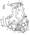
- FIG. 1 is a perspective view of the multiaxis isolation system of the present invention as used in an earth-orbiting spacecraft.
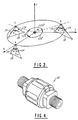
- FIG. 2 is a schematic drawing showing the hexapod geometry of the present invention.
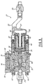
- FIG. 3 is a cross-sectional view of a vibration isolator element constructed in accordance with this invention.
- FIG. 4 is a prospective view of the multiaxis pivot as shown in FIG. 3.
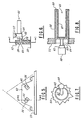
- FIG. 5 is a conceptual side elevation view of one embodiment of the motion limiter elements used to predetermine the allowed deflection of the cradle.
- FIG. 6 is a side elevation view of the motion limiter stops of FIG. 5.
- FIG. 7 is an enlarged end view of the stop assembly of FIG. 6.
- FIG. 8 is a cross-sectional view corresponding with the stop limiter of FIG. 6.
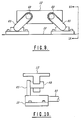
- FIG. 9 is a plan view of a further embodiment of the stop structure of the present invention.
- FIG. 10 is an end view of the structure of FIG .9.
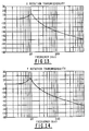
- FIG. 11 is a graph showing transmission loss as a function of frequency for translation along the X-axis.
- FIG. 12 is a graph showing transmission loss as a function of frequency for translation along the Y-axis.
- FIG. 13 is a graph showing transmission loss as a function of frequency for rotation about the X-axis of the preferred embodiment of the invention.
- FIG. 14 is a graph showing transmission loss as a function of frequency for rotation about the Y-axis.
- a preferred embodiment of an isolating system constructed in accordance with the present invention comprises a base or supporting structure 10 and a frame or cradle 12 which is suspended from the supporting structure by a plurality of viscous isolators 14.
- Cradle 12 is provided with a plurality of angularly spaced apart members 16 in the shape of a "Y", with each arm 16 being spaced from another arm 16 substantially by 120 degrees.
- a plurality of mounting surfaces 13 are distributed laterally and equilaterally upon the cradle 12 for mounting the reaction wheel assembly.
- a member 18 extends distally and at right angles to each arm of the cradle for supporting the stem ends of the isolators.
- Each isolator is provided with a flexible joint 20 which permits free translation of an associated isolator through at least two dimensions.
- Such joints may be formed from either spherical bearings or two-axis flexures. In this manner, the plane of the flexible joints supporting the stems is arranged to contain the center of mass of the reaction wheel assembly.
- One isolator stem 22 is provided with a lateral offset so as to clear the stem 24 of the associated isolator.
- the cradle 12 also carries an associated cable and connector 28 for providing electrical connections to the supported structure.
- a stop assembly 26 for limiting the maximum movement of the cradle 12 relative to the supporting structure 10 so that the allowable relative displacement of the cradle is less than that provided for by the design of the isolators.
- the stops to limit isolator motion are shown located at each isolator pair between the supporting structure 10 and cradle 12. This arrangement places the stops in parallel with the isolator elements and as a result the stop contact forces will not be applied through the isolator element and the pivot flexures.
- the stop location can be chosen to accommodate the expected translational motion due to acceleration in the azimuthal direction with allowance for tolerances. Particulars of the stop design are described below.
- the invention is comprised of a system of six identical single degree of freedom isolation elements 14 arranged in a symmetrical pattern of three isolator pairs, in which each pair of elements is connected with a point A, B, or C, 120 degrees apart.
- the elements are grouped in three sets of pairs or bipods, which are attached to the cradle at a radius R in the plane of the reaction wheels' mass center.
- the elements in each isolator pair are skewed by angle from the Z or azimuth axis extending longitudinally and at right angles to the XY plane, with the angle measured about the line connecting the attachment point A, B, or C to the center of mass M.
- the base 30 of each pair of isolator elements is formed by the supporting structure 10.
- each isolator member of each isolator pair is inclined substantially at 38.3 degrees relative to the Z axis.
- the viscous isolator of the present invention will now be described with respect to FIG. 3.
- the isolator 14 includes a base member 32 having outer and inner faces and in which the outer face is coupled to a supporting structure (not shown) by a lower pivot member 20.
- a lower bellows 33 is joined at the first end to the inner face 34 of base 32 and bonded to provide a fluid seal and structural integrity.
- At its upper end lower bellows 33 is bonded to a piston 35, also to provide a fluid seal and structural integrity.
- the bellows 33 is expansible and contractible in an axial direction, and in combination with the base member 32 and piston 35 defines a first fluid chamber which is to be filled with a suitable damping fluid, such as silicone.
- An upper cylindrical housing 36 has a closed end 37 which is structurally affixed to the offset stem 22.
- Cylindrical housing 36 is axially aligned with piston 35 and joined structurally to piston 35 at the open end 38 of housing 36.
- a second bellows 40 is axially aligned with bellows 33 and disposed within upper cylindrical housing 36.
- Bellows 40 is joined at a first end in common with piston 35 and with the open end of cylindrical housing 36.
- a second end of bellows 40 distal to piston 35 is joined to a second cylindrical housing 42 which is coaxially disposed within the upper cylindrical housing 36.
- Bellows 40 is also expansible and contractible in an axial direction of the upper cylindrical housing 36 and is provided with an outer diameter somewhat less than the inner diameter of cylindrical housing 36 and has an inner diameter greater than the cylindrical housing 42 so as to define a second fluid chamber between the exterior of the second cylindrical housing 42 and bellows 40 and joined with piston 35 so as to define a second fluid chamber also filled with damping fluid.
- Piston 35 is provided with an axial bore.
- the cylindrical housing 42 is closed at lower end with the upper end having an end cap provided with an annular bore and having an exterior located flange to form a fluid seal with the second bellows.
- An axial shaft 43 is positioned within the bore of piston 35 to form a radial gap therebetween, the radial gap providing fluid coupling between the first and second fluid chambers.
- Shaft 43 is joined at its lower end to the inner face 34 of base member 32 and its upper end to cylindrical housing 42 and it is provided with an annular bore for fluid coupling to a third fluid chamber, whose function is to be described below.
- a plurality of tuning springs 44 are disposed between the inner face of base 32 and piston 35 and approximately equiangularly disposed about the circumference of the first bellows 33.
- Coil springs are placed in parallel with the main bellows and adjusted to obtain the required stiffness, approximately one-third of which being allocated to the multiple bellows and two-thirds to the springs.
- One isolator in each pair further includes a stem 22 which may be offset as shown and which is affixed to housing 36 so as to move piston 35 axially when the force is applied to upper pivot 20, while the offset allows the stem of an adjacent isolator to move freely while minimizing the space requirements of the supports.
- a stem 22 which may be offset as shown and which is affixed to housing 36 so as to move piston 35 axially when the force is applied to upper pivot 20, while the offset allows the stem of an adjacent isolator to move freely while minimizing the space requirements of the supports.
- a third bellows 45 is used to provide a redundant seal over first bellows 33 and provides a fluid seal between the base 32 and piston 35.
- Piston 35 and base 32 are provided with a fluid passage to allow pressure communication between bellows 45 and the enclosure defined by the cylindrical housing 36 and cylindrical housing 42. Its purpose is to allow atmospheric pressure equalization and to allow evacuation, thus simulating space conditions.
- a vent port 46 is used for this purpose.
- Fluid port 47 is used to fill the fluid chambers with a damping fluid.
- Fluid volume variation with temperature change is compensated for by a spring-loaded piston acting to pressurize the damping fluid.
- a small fluid passage in the axial shaft joins the compensator volume to the main fluid volume at the midpoint of the annular passage where the fluid pressure is maintained substantially constant with temperature.
- This temperature compensation is provided by a thermal compensator bellows 48 disposed within cylindrical housing 42 and sealed by lower end cap 50 and enclosed by the upper end cap of cylindrical housing 42.
- Temperature compensator spring 52 is arranged to apply a predetermined pressure on lower end cap 50 so as to pressurize the damping fluid effectively to one half the peak pressure obtained in operation.
- Fluid expansion due to temperature increase causes temperature compensator bellows 48 to contract thereby allowing additional space for the expanded fluid while maintaining the predetermined pressure by temperature compensator spring 52, thereby relieving an over- pressure condition in the first and second fluid chambers and damping gap of the isolator to maintain a substantially constant system pressure.
- the axial force maintained on thermal compensator bellows 48 by preload spring 52 establishes a positive pressure on the damping fluid over a wide range of temperature conditions.
- FIG. 4 is a perspective view of a preferred embodiment of the flexure pivot.
- the pivots at each end of the isolator have two angular degrees of freedom. Since they consist of two right angle bending elements, machined into a solid cylinder, they introduce no friction into the system. Having relatively low stiffness, the flexures preclude significant bending loads on the isolator.
- bellows 33 and bellows 45 contract, thereby reducing the capacity of fluid chamber 54, so that the force exerted by the fluid therein increases. If lower pivot 20 moves in a direction such that it extends out from main cylinder housing 36, on the other hand, some of the fluid in fluid chamber 53 flows into fluid chamber 54 between the base 32 and piston 35. Also, in this case, bellows 40 extends and the fluid flows past the restrictive radial gap in piston 35 so that motion of stem 22 is damped.
- FIG. 5 is a conceptual plan view showing schematically the supporting structure 10, motion limiting aperture 26, and motion stops 60 and 61.
- the stops 60 and 61 are supported from the cradle; however, in an alternate embodiment stops 60 and 61 may be joined to supporting structure 10 and operatively limiting apertures provided in the cradle 12. This alternate structure is shown in FIG. 9 and FIG. 10.
- member 62 is affixed to base structure 10 and provided with motion limiter apertures 26 which are configured to allow free motion of stops 60 and 61, respectively, within predetermined limits.
- Stop assembly 60 is shown in side view.
- Member 62 has defined within an aperture therein motion limiter 26.
- Stop member 60 is comprised of a coaxial tube assembly 63 which in this view is supported from the cradle 12, including a bearing assembly 64, within which a portion of tube assembly 63 is allowed to rotate, and a crank 65 to which is affixed stop member 60.
- An end view taken through 7-7 of FIG. 6 is shown in FIG. 7.
- Tube assembly 63 supports crank or stop arm 65 which is affixed to stop member 60.
- Tube assembly 63 is seen to be supported by bearing assembly.
- Tube assembly 63 is comprised of first and second coaxial tubes 66, 67 disposed in parallel to the plane of the cradle 12 and are joined at end 68 by welding, braising, or other similar means.
- Outer tube 66 is secured to the cradle 12 at one end.
- the free end of inner tube 67 is provided with a shaft 69 which extends through support bearing 64 to crank arm 65.
- Crank arm 65 is in turn provided with stop member 60 at right angles to shaft 69.
- stop member 60 In response to deflection of cradle 12 induced by motion of the supported structure, stop member 60 will be caused to engage aperture 26 after a predetermined deflection of the cradle.
- FIGS. 9 and 10 show an alternate embodiment of the motion limiting structure.
- Cradle 12 is provided with slots to receive a stop 60 which again engages crank arm 65 to produce a limiting force from the coaxial tube assembly 63, here secured to base 10.
- the deterministic design of the isolators allows calculation to establish the required amount of damping and the required stiffness of the elastic members when given the force, direction of force, frequency range, amplitudes and directions of vibrations to be expected.
- the kinematic structure is adaptable to deformation of the supporting structure as well as mounting errors of the flexure joints connecting the isolator elements to the structures without applying undesired constraints.
- Element design requirements can be derived from the system frequency and peaking (Q) requirements.
- the element stiffness (K), damping constant (C), and skew angle ( ⁇ ) can, for example, be selected to match the X/Y translational frequency (fx), the X/Y rotational frequency (fx) and the X/Y translational peaking frequency (Qx).
- the system may be provided with significantly increased stiffness with respect to the movement of the cradle along the Z axis. More specifically, the axial restraint attributable to the stiffness of the suspension elements about their axes varies with the cosine squared of the angle. Consequently, the axial stiffness of the system will decrease as the angle is increased.
- FIG. 11 shows that the translation transmissibility along the X axis reaches a peak at 4 Hz and attenuates rapidly thereafter.
- Y axis translation follows a similar characteristic as shown in FIG. 12.
- FIGS. 13 and 14 show the corresponding rotation transmissibility characteristics along the X rotation axis and the Y rotation axis, reaching a peak at approximately 9 to 10 Hz.
- a resonant frequency of 9 to 10 Hz is required for X and Y axis rotation in order to provide rigidity for the magnetic suspension contol torques to be effectively applied.
- substantial isolation is obtained over a large frequency range in the X and Y coordinates, while allowing transmission of the desired control torque frequencies about the X, Y, and Z axes.
- Stop stiffness is set to provide a compromise between the peak deflections under the launch conditions and the peak impact loads.
- the isolator element design also permits the use of a nonlinear damping technique to provide a higher damping constant during launch than in operation. Higher damping would reduce the impact loads without the necessity of increasing the stroke.
- tuning springs provides a low cost, convenient technique to tune the stiffness of the isolator element to provide a very tightly controlled frequency response.
- the tuning springs are positioned in a way that does not increase the interface dimensions.
- the upper and lower bellows are designed to provide approximately one third of the needed element stiffness, the tuning springs and the redundant seal bellows providing the remainder.
- a metal bellows is preferred over synthetic rubber or other polymers because of the better dimensional and stiffness controls offered.
- the damping coefficient can be changed significantly by using a different viscosity damping fluid. Thus, the design offers significant flexibility in optimizing performance.
- the isolator structure is also applicable for providing vibration isolation and damping in the absence of such control torques.
- the isolator elements have been skewed at a predetermined angle with respect to the Z axis, with the base of the isolator pairs and the upper joints of the isolators at a common radius R from the Z axis, other attitudes of the isolators may be desirable where the base and upper joints are constructed at differing radii to favor a desired translational or rotational axis transmissibility characteristic.
Landscapes
- Engineering & Computer Science (AREA)
- General Engineering & Computer Science (AREA)
- Mechanical Engineering (AREA)
- Remote Sensing (AREA)
- Aviation & Aerospace Engineering (AREA)
- Chemical & Material Sciences (AREA)
- Combustion & Propulsion (AREA)
- Radar, Positioning & Navigation (AREA)
- Physics & Mathematics (AREA)
- Acoustics & Sound (AREA)
- Vibration Prevention Devices (AREA)
Description
- The present invention relates to a vibration isolating and damping apparatus according to one of the independent claims which serves for isolating a reaction wheel assembly on a supporting structure while permitting a mounting base to be moved relative to the supporting structure along multiple axes of freedom.
- Spacecraft reaction wheel assemblies used for pointing control systems, as on a telescope, can emit vibrations into the spacecraft structure that result in blurred images in optical sensors carried by the spacecraft. A reaction wheel assembly produces vibration disturbances when it rotates due to imperfections in the electromagnetics and their drive electronics, unbalance of the rotor, and imperfections in the spin bearings. Since the reaction wheel assemblies provide a desired control torque for positioning the optical elements in the absence of a chemical reaction propulsion system, the isolation system provide attenuation above specific natural frequencies and must have peaking factors in one or more degrees of freedom without impairing transmission of the desired control torques. To maintain accuracy, vibrations must be isolated between the supported structure and the supporting system during both ground loading (one G) and in orbit (zero G).
- An apparatus according to the preamble of claim 1 is disclosed in US-A-3,540,688, wherein a supporting system employs pivoted single-axis isolators arranged into a bipod and a tetrahedron in which the isolators are supported by means of universally rotatable joints to provide a kinematic mount system.
- US-A-4,848,525 discloses an active 6 degree-of-freedom pointing and isolation system having a magnetically suspended positioning system mounted above a hexapod of linear actuators.
- Critical to the above isolation systems is the design of the isolator element. Typically, the prior art isolator elements have been designed for relatively high frequencies, of the order of 15 Hz or greater; therefore, deflections due to one G ground loading and launch vibrations were relatively small and not a limiting factor. However, in some applications the vibration isolator is required to provide specific natural frequencies and peaking factors in one or more degrees of freedom. Thus, for an application with a magnetically suspended wheel the radial translation motion was required to be isolated at a relatively low frequency (4.0 Hz), and very tightly controlled frequencies and peaking factors were specified for all six degrees of freedom to avoid interaction with the magnetic suspension control system. Moreover, the isolator was required to operate in both ground and orbit environments. With the prior art isolator the radial translational frequency at 4 Hz could not be accurately controlled.
- Moreover, viscous damped isolators are designed to produce damping in their axial direction by fluid shear through a controlled annulus. Damping in the radial direction is typically very low as compared to axial damping and not accurately controlled. Therefore, the peaking factor of the radial translational isolator frequency could not be accurately controlled. Further, radial deflection was limited to the radial clearance of the annulus which must be relatively small to achieve good axial and radial damping. A low frequency radial translational isolator requires a larger value of radial motion than can be provided by the prior art isolators. Still further, the small radial gap coupled with the low radial stiffness precludes operation in the radial direction at one G, and results in the isolator chattering between its stops during launch vibration with the resultant transmittal of impact loads to the reaction wheel assembly.
It is therefore the object of the present invention to devise a vibration isolating and damping apparatus which does not have the above mentioned limitations. This object is achieved by the features of independent claim 1. Further advantageous embodiments of the inventive apparatus may be taken from the dependent claims. - The present invention avoids the foregoing limitations by providing a hexapod of isolation elements pivoted at each end to carry only axial loads. Travel limiting stops are build into the structure so as to avoid transmitting the loads caused by impact during launch to the isolator elements. A tunable viscous damper is provided which may be peaked at a desired resonant frequency.
- The present invention overcomes the problems of the prior art by providing a vibration isolating and damping apparatus that passively isolates vibrations between a supporting structure and a supported structure while permitting movement of the supported structure over six degrees of freedom with respect to the supporting structure.
- Preferably, three sets of isolators, skewed at a predetermined angle, are grouped into bipods or pairs which are attached to the supported structure in the plane of the payload mass center. Each of the isolator elements is pivoted at each end so that only axial loads are carried by the elements during rotation and translation of the payload. Travel limiting stops may be build into the apparatus so as to maximize the allowable deflection of the supported structure and avoid transmitting impact loads through the isolator angular pivots.
- Prefered embodiments of the invention are defined by the dependent claims,
- FIG. 1 is a perspective view of the multiaxis isolation system of the present invention as used in an earth-orbiting spacecraft.
- FIG. 2 is a schematic drawing showing the hexapod geometry of the present invention.
- FIG. 3 is a cross-sectional view of a vibration isolator element constructed in accordance with this invention.
- FIG. 4 is a prospective view of the multiaxis pivot as shown in FIG. 3.
- FIG. 5 is a conceptual side elevation view of one embodiment of the motion limiter elements used to predetermine the allowed deflection of the cradle.
- FIG. 6 is a side elevation view of the motion limiter stops of FIG. 5.
- FIG. 7 is an enlarged end view of the stop assembly of FIG. 6.
- FIG. 8 is a cross-sectional view corresponding with the stop limiter of FIG. 6.
- FIG. 9 is a plan view of a further embodiment of the stop structure of the present invention.
- FIG. 10 is an end view of the structure of FIG .9.
- FIG. 11 is a graph showing transmission loss as a function of frequency for translation along the X-axis.
- FIG. 12 is a graph showing transmission loss as a function of frequency for translation along the Y-axis.
- FIG. 13 is a graph showing transmission loss as a function of frequency for rotation about the X-axis of the preferred embodiment of the invention.
- FIG. 14 is a graph showing transmission loss as a function of frequency for rotation about the Y-axis.
- With reference to the drawings and particularly to Figs. 1 and 2, a preferred embodiment of an isolating system constructed in accordance with the present invention comprises a base or supporting
structure 10 and a frame orcradle 12 which is suspended from the supporting structure by a plurality ofviscous isolators 14.Cradle 12 is provided with a plurality of angularly spaced apartmembers 16 in the shape of a "Y", with eacharm 16 being spaced from anotherarm 16 substantially by 120 degrees. A plurality ofmounting surfaces 13 are distributed laterally and equilaterally upon thecradle 12 for mounting the reaction wheel assembly. Amember 18 extends distally and at right angles to each arm of the cradle for supporting the stem ends of the isolators. Each isolator is provided with aflexible joint 20 which permits free translation of an associated isolator through at least two dimensions. Such joints may be formed from either spherical bearings or two-axis flexures. In this manner, the plane of the flexible joints supporting the stems is arranged to contain the center of mass of the reaction wheel assembly. Oneisolator stem 22 is provided with a lateral offset so as to clear thestem 24 of the associated isolator. Thecradle 12 also carries an associated cable andconnector 28 for providing electrical connections to the supported structure. - Provision is made by a
stop assembly 26 for limiting the maximum movement of thecradle 12 relative to the supportingstructure 10 so that the allowable relative displacement of the cradle is less than that provided for by the design of the isolators. In one embodiment, shown in FIGS. 5-8 the stops to limit isolator motion are shown located at each isolator pair between the supportingstructure 10 andcradle 12. This arrangement places the stops in parallel with the isolator elements and as a result the stop contact forces will not be applied through the isolator element and the pivot flexures. The stop location can be chosen to accommodate the expected translational motion due to acceleration in the azimuthal direction with allowance for tolerances. Particulars of the stop design are described below. - Referring now to FIG. 2, the invention is comprised of a system of six identical single degree of
freedom isolation elements 14 arranged in a symmetrical pattern of three isolator pairs, in which each pair of elements is connected with a point A, B, or C, 120 degrees apart. The elements are grouped in three sets of pairs or bipods, which are attached to the cradle at a radius R in the plane of the reaction wheels' mass center. The elements in each isolator pair are skewed by angle from the Z or azimuth axis extending longitudinally and at right angles to the XY plane, with the angle measured about the line connecting the attachment point A, B, or C to the center of mass M. In the preferred embodiment, thebase 30 of each pair of isolator elements is formed by the supportingstructure 10. In the preferred embodiment, each isolator member of each isolator pair is inclined substantially at 38.3 degrees relative to the Z axis. - The viscous isolator of the present invention will now be described with respect to FIG. 3. The
isolator 14 includes abase member 32 having outer and inner faces and in which the outer face is coupled to a supporting structure (not shown) by alower pivot member 20. A lower bellows 33 is joined at the first end to the inner face 34 ofbase 32 and bonded to provide a fluid seal and structural integrity. At its upper end lower bellows 33 is bonded to apiston 35, also to provide a fluid seal and structural integrity. The bellows 33 is expansible and contractible in an axial direction, and in combination with thebase member 32 andpiston 35 defines a first fluid chamber which is to be filled with a suitable damping fluid, such as silicone. An uppercylindrical housing 36 has aclosed end 37 which is structurally affixed to the offsetstem 22.Cylindrical housing 36 is axially aligned withpiston 35 and joined structurally topiston 35 at theopen end 38 ofhousing 36. A second bellows 40 is axially aligned withbellows 33 and disposed within uppercylindrical housing 36.Bellows 40 is joined at a first end in common withpiston 35 and with the open end ofcylindrical housing 36. A second end ofbellows 40 distal topiston 35 is joined to a secondcylindrical housing 42 which is coaxially disposed within the uppercylindrical housing 36.Bellows 40 is also expansible and contractible in an axial direction of the uppercylindrical housing 36 and is provided with an outer diameter somewhat less than the inner diameter ofcylindrical housing 36 and has an inner diameter greater than thecylindrical housing 42 so as to define a second fluid chamber between the exterior of the secondcylindrical housing 42 and bellows 40 and joined withpiston 35 so as to define a second fluid chamber also filled with damping fluid. -
Piston 35 is provided with an axial bore. Thecylindrical housing 42 is closed at lower end with the upper end having an end cap provided with an annular bore and having an exterior located flange to form a fluid seal with the second bellows. Anaxial shaft 43 is positioned within the bore ofpiston 35 to form a radial gap therebetween, the radial gap providing fluid coupling between the first and second fluid chambers.Shaft 43 is joined at its lower end to the inner face 34 ofbase member 32 and its upper end tocylindrical housing 42 and it is provided with an annular bore for fluid coupling to a third fluid chamber, whose function is to be described below. - Since the bellows are designed with low stiffness, a plurality of tuning springs 44 are disposed between the inner face of
base 32 andpiston 35 and approximately equiangularly disposed about the circumference of the first bellows 33. Coil springs are placed in parallel with the main bellows and adjusted to obtain the required stiffness, approximately one-third of which being allocated to the multiple bellows and two-thirds to the springs. - One isolator in each pair further includes a
stem 22 which may be offset as shown and which is affixed tohousing 36 so as to movepiston 35 axially when the force is applied toupper pivot 20, while the offset allows the stem of an adjacent isolator to move freely while minimizing the space requirements of the supports. - A third bellows 45 is used to provide a redundant seal over
first bellows 33 and provides a fluid seal between the base 32 andpiston 35.Piston 35 andbase 32 are provided with a fluid passage to allow pressure communication betweenbellows 45 and the enclosure defined by thecylindrical housing 36 andcylindrical housing 42. Its purpose is to allow atmospheric pressure equalization and to allow evacuation, thus simulating space conditions. Avent port 46 is used for this purpose. Fluid port 47 is used to fill the fluid chambers with a damping fluid. - Fluid volume variation with temperature change is compensated for by a spring-loaded piston acting to pressurize the damping fluid. A small fluid passage in the axial shaft joins the compensator volume to the main fluid volume at the midpoint of the annular passage where the fluid pressure is maintained substantially constant with temperature. This temperature compensation is provided by a thermal compensator bellows 48 disposed within
cylindrical housing 42 and sealed bylower end cap 50 and enclosed by the upper end cap ofcylindrical housing 42.Temperature compensator spring 52 is arranged to apply a predetermined pressure onlower end cap 50 so as to pressurize the damping fluid effectively to one half the peak pressure obtained in operation. Fluid expansion due to temperature increase causes temperature compensator bellows 48 to contract thereby allowing additional space for the expanded fluid while maintaining the predetermined pressure bytemperature compensator spring 52, thereby relieving an over- pressure condition in the first and second fluid chambers and damping gap of the isolator to maintain a substantially constant system pressure. The axial force maintained on thermal compensator bellows 48 bypreload spring 52 establishes a positive pressure on the damping fluid over a wide range of temperature conditions. - Affixed to the
base 32 ofisolator 14 is alower pivot 20 and affixed to thestem 22 is anupper pivot 20 of identical construction. By providing these freely moving joints at both ends of the isolator element, an impact or vibratory load in any direction applied tocradle 12 is translated into only axial load in its movement of the isolator elements. The springs and dampers therefore can be optimized for performance along one degree of freedom. FIG. 4 is a perspective view of a preferred embodiment of the flexure pivot. The pivots at each end of the isolator have two angular degrees of freedom. Since they consist of two right angle bending elements, machined into a solid cylinder, they introduce no friction into the system. Having relatively low stiffness, the flexures preclude significant bending loads on the isolator. - The operation of
isolator 14, constructed in this manner, will now to be described. Whenlower pivot 20 moves in an axial direction such thatbase 32 is pushed toward fluid chamber 54, some of the damping fluid in fluid chamber 54 flows intofluid chamber 53 via the radial gap formed in the annular bore ofpiston 35. As the damping fluid flows throughpiston 35 in this manner, a damping force is produced by the viscous resistance of the fluid withaxial shaft 43. As a result,piston 35 is subjected to this resistance and compresses bellows 40. At the same time, the fluid influid chamber 53 is compressed in accordance with the depth of compression oflower pivot 20. Accordingly, bellows 33 and bellows 45 contract, thereby reducing the capacity of fluid chamber 54, so that the force exerted by the fluid therein increases. Iflower pivot 20 moves in a direction such that it extends out frommain cylinder housing 36, on the other hand, some of the fluid influid chamber 53 flows into fluid chamber 54 between the base 32 andpiston 35. Also, in this case, bellows 40 extends and the fluid flows past the restrictive radial gap inpiston 35 so that motion ofstem 22 is damped. - In response to the movement of
lower pivot 20 in the extending direction fluid chamber 54 increases in capacity, so that bellows 33 and 45 extend. Thus, aslower pivot 20 repeatedly extends and contracts relative to stem 22, or stem 22 extends and contracts relative tolower pivot 20, the isolator serves as both shock absorber, vibration absorber, and damper. - Referring now to FIGS. 5-8, there are shown the structures limiting the device which protects the isolator elements from excessive excursions imposed during launch and in zero gravity space. FIG. 5 is a conceptual plan view showing schematically the supporting
structure 10,motion limiting aperture 26, and motion stops 60 and 61. In the structure illustrated, thestops structure 10 and operatively limiting apertures provided in thecradle 12. This alternate structure is shown in FIG. 9 and FIG. 10. With continued reference to FIG. 5,member 62 is affixed tobase structure 10 and provided withmotion limiter apertures 26 which are configured to allow free motion ofstops Member 62 has defined within an aperture thereinmotion limiter 26.Stop member 60 is comprised of acoaxial tube assembly 63 which in this view is supported from thecradle 12, including a bearingassembly 64, within which a portion oftube assembly 63 is allowed to rotate, and a crank 65 to which is affixedstop member 60. An end view taken through 7-7 of FIG. 6 is shown in FIG. 7.Tube assembly 63 supports crank or stoparm 65 which is affixed to stopmember 60.Tube assembly 63 is seen to be supported by bearing assembly. - Referring now to FIG. 8, a detailed view of the tube assembly is shown.
Tube assembly 63 is comprised of first and secondcoaxial tubes cradle 12 and are joined atend 68 by welding, braising, or other similar means.Outer tube 66 is secured to thecradle 12 at one end. The free end ofinner tube 67 is provided with ashaft 69 which extends through support bearing 64 to crankarm 65.Crank arm 65 is in turn provided withstop member 60 at right angles toshaft 69. In response to deflection ofcradle 12 induced by motion of the supported structure,stop member 60 will be caused to engageaperture 26 after a predetermined deflection of the cradle. This will causefree arm 65 to apply a torque toinner tube 67 and resiliently apply a predetermined counterforce to cradle 12 thereby restraining the isolator elements from deflection greater than a predetermined value which is established from the spring constant of thetube assembly 63, and using the dimensions ofstop member 60 andmotion limiter aperture 26. - FIGS. 9 and 10 show an alternate embodiment of the motion limiting structure.
Cradle 12 is provided with slots to receive astop 60 which again engages crankarm 65 to produce a limiting force from thecoaxial tube assembly 63, here secured tobase 10. - It may be seen from the foregoing that the deterministic design of the isolators allows calculation to establish the required amount of damping and the required stiffness of the elastic members when given the force, direction of force, frequency range, amplitudes and directions of vibrations to be expected. The kinematic structure is adaptable to deformation of the supporting structure as well as mounting errors of the flexure joints connecting the isolator elements to the structures without applying undesired constraints.
- Element design requirements can be derived from the system frequency and peaking (Q) requirements. The element stiffness (K), damping constant (C), and skew angle (α) can, for example, be selected to match the X/Y translational frequency (fx), the X/Y rotational frequency (fx) and the X/Y translational peaking frequency (Qx). The steady state frequency response can be computed from the known constants and transfer functions as shown in FIGS. 11-14. It is also possible to select the skew angle (α) for isoelastic stiffness where Kx = Ky = Kz. By arranging the isolator elements inclined relative to the azimuth axis, the system may be provided with significantly increased stiffness with respect to the movement of the cradle along the Z axis. More specifically, the axial restraint attributable to the stiffness of the suspension elements about their axes varies with the cosine squared of the angle. Consequently, the axial stiffness of the system will decrease as the angle is increased.
- FIG. 11 shows that the translation transmissibility along the X axis reaches a peak at 4 Hz and attenuates rapidly thereafter. Y axis translation follows a similar characteristic as shown in FIG. 12. FIGS. 13 and 14 show the corresponding rotation transmissibility characteristics along the X rotation axis and the Y rotation axis, reaching a peak at approximately 9 to 10 Hz. A resonant frequency of 9 to 10 Hz is required for X and Y axis rotation in order to provide rigidity for the magnetic suspension contol torques to be effectively applied. Thus, substantial isolation is obtained over a large frequency range in the X and Y coordinates, while allowing transmission of the desired control torque frequencies about the X, Y, and Z axes.
- Stop stiffness is set to provide a compromise between the peak deflections under the launch conditions and the peak impact loads. The isolator element design also permits the use of a nonlinear damping technique to provide a higher damping constant during launch than in operation. Higher damping would reduce the impact loads without the necessity of increasing the stroke.
- The novel use of tuning springs provides a low cost, convenient technique to tune the stiffness of the isolator element to provide a very tightly controlled frequency response. The tuning springs are positioned in a way that does not increase the interface dimensions. The upper and lower bellows are designed to provide approximately one third of the needed element stiffness, the tuning springs and the redundant seal bellows providing the remainder. A metal bellows is preferred over synthetic rubber or other polymers because of the better dimensional and stiffness controls offered. The damping coefficient can be changed significantly by using a different viscosity damping fluid. Thus, the design offers significant flexibility in optimizing performance.
- While the present invention has been adapted to provide a complex mechanical impedance as a function of frequency which allows transmission of control torque producing frequencies while suppressing undesired vibration frequencies, it is clear that the isolator structure is also applicable for providing vibration isolation and damping in the absence of such control torques. Moreover, while the isolator elements have been skewed at a predetermined angle with respect to the Z axis, with the base of the isolator pairs and the upper joints of the isolators at a common radius R from the Z axis, other attitudes of the isolators may be desirable where the base and upper joints are constructed at differing radii to favor a desired translational or rotational axis transmissibility characteristic.
Claims (10)
- Vibration isolating and damping apparatus for passively isolating vibrations between a supporting structure (10) and a supported structure while permitting movement of the supported structure over six degrees of freedom with respect to the supporting structure, said apparatus comprising:
a plurality of isolators (14), each isolator having a body, a first end flexibly secured to said supporting structure, and a second end,
a flexible joint (20) at each of said first and second ends of said isolators adapted to provide at least two degrees of freedom of motion so that opposite ends of each said isolator are relatively moveable in a direction perpendicular to the axis of the respective isolator, said ends of each of said isolators being movable relative to each other along their respective longitudinal axis while maintaining said supported structure in kinematic relation with said supporting structure, and
said isolators (14) providing a predetermined complex impedance as a function of vibration frequency and adapted for transmission of externally applied control torques over a given vibration frequency range across said vibration isolating and damping apparatus,
characterized by:
a cradle (12) supporting said supported structure with said second end of each isolator (14) being flexibly secured to said cradle (12) so that said isolators support said cradle with respect to said supporting structure with pairs of said isolators having a common base (30) on said supporting structure and having intersecting longitudinal axes disposed to define a substantially isosceles triangle at a predetermined acute angle with respect to said base with the plane formed by each pair of said isolators being substantially parallel to an azimuthal axis (Z) passing through said supporting structure and said cradle, said isolators being arranged in substantially equiangularly disposed pairs about said azimuthal axis. - Apparatus according to claim 1, characterized in that said isolators (14) are arranged in three pairs substantially 120 degrees apart, each body of each isolator pair being inclined substantially at 38.3 degrees relative to the plane of said supported structure.
- Apparatus according to claim 2, characterized in that said cradle (12) further comprising a plurality of mounting surfaces (13) for said supported structure distributed laterally and equiangularly thereupon and further comprising a member (18) associated with each said pair of isolators extending at right angles to said cradle for supporting said second ends of said isolators so that the plane of said flexible joints (20) thereat contains the center of mass of said supported structure.
- Apparatus according to claim 3, characterized in that said isolator (14) comprises a viscous isolator.
- Apparatus according to claim 4, characterized in that said isolator (14) is comprised of a stem (22) extending from said second end of said body in a direction opposite to the supporting structure (10), at least one said stem in each isolator pair having a portion laterally offset, for providing a clearance between stems of associate isolators.
- Apparatus according to claim 5, further characterized by means (26; 60-68) limiting the maximum movement of said cradle (12) relative to said supporting structure (10), which movement is less than the maximum movement of said cradle relative to said supporting structure provided for by said isolators.
- Apparatus according to claim 6, characterized in that said means limiting the maximum movement of said cradle is comprised of first and second coaxial metallic tubes (66, 67), said tubes disposed in parallel to the plane of said cradle (12) and radial to said azimuthal axis passing through said cradle, being joined at a first end (68) proximate to said azimuthal axis, said first tube (66) being affixed to said cradle (12) proximate to said isolator pairs, said supporting structure (10) having affixed thereto a member (62) being provided with an aperture (26) having a predetermined clearance for a stop member (60) extending radially and outwardly, said stop member affixed to a second end of said second tube (67) via a stop arm (65) and a shaft (69) and disposed for constraining motion of said cradle relative to said supporting structure, whereat a predetermined deflection of said cradle induced by motion of said supported structure will cause said stop arm resiliently to apply a predetermined counterforce to said cradle, thereby restraining said isolator from deflection greater than a predetermined value.
- Apparatus according to one of claims 1 to 7, characterized by said isolator (14) comprising:a) a base member (32) having outer and inner faces and means (20) for attaching said outer face of said base member to said supporting structure (10);b) a first bellows (33) having a first end joined to said inner face of said base member (32) for forming a fluid seal and having a second end joined to a first face of an axially aligned piston (35), said bellows being expansible and contractible in an axial direction thereof, said base member, said first bellows, and said piston defining a first fluid chamber (54) filled with fluid;c) a first main cylindrical housing (36) having a closed first end and an open second end, axially aligned with said piston (35) and circumferentially joined with said second face of said piston at said open end;d) a second bellows (40) axially aligned with said first bellows (33), received within said first main cylindrical housing (36) and having a first end joined to said second face of said piston and a second end joined to a second hollow cylindrical housing (42) coaxially disposed within said first main cylindrical housing (36), said second bellows (40) being expansible and contractible in an axial direction of said first main cylindrical housing (36), said second bellows having an outer diameter less than an inner diameter of said first main cylindrical housing and an inner diameter greater than said second hollow cylindrical housing (42), an exterior of said second hollow cylindrical housing and said second bellows and said piston defining a second fluid chamber (53) filled with fluid communicating with said first fluid chamber (54) through an axial bore in said piston;e) said second hollow cylindrical housing (42) having first and second closed ends and an annular bore and having an exterior centrally located flange forming a fluid seal with said second bellows (40);f) an axial shaft (43) slideably disposed within an axial bore of said piston (35), said axial shaft distally joined to said interior face of said base member (32) and proximally joined to that end of the said second cylindrical housing which is directed to said piston, said axial bore forming a radial gap with said axial shaft, said radial gap providing fluid coupling between said first and second fluid chambers;g) tuning spring means (44) disposed between said interior face of said base (32) and said first face of said piston (35) and circumferentially disposed about said first bellows (33) for providing a predetermined axial stiffness; andh) stem means (22) connected to said first main cylindrical housing (36) at said closed first end, adapted to move said piston (35) axially when a force is applied to said stem means and to damp reciprocation of said stem means by utilizing viscous resistance of the fluid when said stem means moves in the axial direction of said first main cylindrical housing.
- Apparatus according to claim 8, further characterized by thermal compensator means, said thermal compensator means comprising:a) a thermal compensator bellows (48) disposed within said second cylindrical housing (42) and having a first end forming a fluid seal with an end cap defined by said second closed end of said second cylindrical housing, said thermal compensator bellows and said second cylindrical housing defining a third fluid chamber filled with fluid and fluidly coupled through a fluid passage in said axial shaft to said radial gap and to said first and second fluid chambers; andb) a compensator spring (52) disposed within said annular bore of said second cylindrical housing and disposed within and coupled to said thermal compensator bellows for establishing positive pressure on said fluid with variations in temperature while allowing expansion or contraction of fluid volume by cooperating with corresponding contraction or expansion of said thermal compensation bellows.
- Apparatus according to claim 9, further characterized by a third extensible and contractible bellows (45) enclosing said first bellows (33) and having an outer diameter disposed within said circumferentially disposed timing springs and providing a fluid seal between said inner face of said base (32) and said first face of said piston, said piston (35) having a further passage allowing pressure communication between said third bellows and said enclosure defined by said first main cylindrical housing and said second cylindrical housing.
Applications Claiming Priority (2)
| Application Number | Priority Date | Filing Date | Title |
|---|---|---|---|
| US785726 | 1991-10-31 | ||
| US07/785,726 US5305981A (en) | 1991-10-31 | 1991-10-31 | Multiaxis vibration isolation system |
Publications (2)
| Publication Number | Publication Date |
|---|---|
| EP0539930A1 EP0539930A1 (en) | 1993-05-05 |
| EP0539930B1 true EP0539930B1 (en) | 1995-09-06 |
Family
ID=25136449
Family Applications (1)
| Application Number | Title | Priority Date | Filing Date |
|---|---|---|---|
| EP92118397A Expired - Lifetime EP0539930B1 (en) | 1991-10-31 | 1992-10-28 | Multiaxis isolation system |
Country Status (4)
| Country | Link |
|---|---|
| US (1) | US5305981A (en) |
| EP (1) | EP0539930B1 (en) |
| JP (1) | JP3375996B2 (en) |
| DE (1) | DE69204619T2 (en) |
Families Citing this family (80)
| Publication number | Priority date | Publication date | Assignee | Title |
|---|---|---|---|---|
| US5435531A (en) * | 1993-08-18 | 1995-07-25 | Bell Helicopter Textron Inc. | Vibration isolation system |
| US5820079A (en) * | 1994-04-05 | 1998-10-13 | Hughes Electronics | Mechanism for mounting and actuating a momentum wheel with high vibration isolation |
| US5505422A (en) * | 1994-06-02 | 1996-04-09 | Bio-Rad Laboratories | Top adjustable kinematic mount |
| US5492312A (en) * | 1995-04-17 | 1996-02-20 | Lord Corporation | Multi-degree of freedom magnetorheological devices and system for using same |
| DE69515989T2 (en) * | 1995-05-11 | 2000-12-21 | Raytheon Co., El Segundo | Device for mounting and operating a flywheel with high vibration isolation |
| US5750897A (en) * | 1995-06-14 | 1998-05-12 | Canon Kabushiki Kaisha | Active anti-vibration apparatus and method of manufacturing the same |
| US6059253A (en) * | 1996-05-14 | 2000-05-09 | Sears Manufacturing Company | Active suspension system for vehicle seats |
| US6022005A (en) * | 1996-09-27 | 2000-02-08 | Trw Inc. | Semi-active vibration isolator and fine positioning mount |
| US5971375A (en) * | 1996-11-26 | 1999-10-26 | Trw Inc. | Isolator apparatus for multi-dimensional vibrational disturbances |
| US5918865A (en) * | 1997-01-29 | 1999-07-06 | Honeywell Inc. | Load isolator apparatus |
| US5803213A (en) * | 1997-02-03 | 1998-09-08 | Honeywell Inc. | Heavy load vibration isolation apparatus |
| US5947240A (en) * | 1997-02-03 | 1999-09-07 | Honeywell, Inc. | Load vibration isolation apparatus |
| US6003849A (en) * | 1997-03-04 | 1999-12-21 | Honeywell Inc. | Hybrid isolator and structural control actuator strut |
| US6082508A (en) * | 1997-04-23 | 2000-07-04 | Honeywell International Inc. | Pneumatic damping strut |
| US6012680A (en) * | 1997-06-27 | 2000-01-11 | Mcdonnell Douglas Corporation | Passive lateral vibration isolation system for a spacecraft launch vehicle |
| US6390254B1 (en) * | 1997-07-10 | 2002-05-21 | Honeywell International Inc. | Constant volume damper |
| US5979882A (en) * | 1997-11-22 | 1999-11-09 | Honeywell Inc. | Direct fluid shear damper |
| US6129185A (en) * | 1997-12-30 | 2000-10-10 | Honeywell International Inc. | Magnetically destiffened viscous fluid damper |
| JP3978861B2 (en) * | 1998-04-22 | 2007-09-19 | 株式会社Ihi | Payload buffer support mechanism |
| US6340137B1 (en) * | 1998-08-26 | 2002-01-22 | Honeywell International Inc. | Moment control unit for spacecraft attitude control |
| AU5679900A (en) * | 1999-06-15 | 2001-01-02 | Haweka Auswuchttechnik Horst Warkotsch Gmbh | Clamping mechanism for clamping a wheel of a motorcycle onto the shaft of a balancing machine |
| US6325351B1 (en) * | 2000-01-05 | 2001-12-04 | The Regents Of The University Of California | Highly damped kinematic coupling for precision instruments |
| US6805337B1 (en) * | 2000-03-02 | 2004-10-19 | Omnitek Research & Development, Inc. | Apparatus for isolation of payloads with low transmissibility |
| US6202961B1 (en) | 2000-03-21 | 2001-03-20 | Csa Engineering | Passive, multi-axis, highly damped, shock isolation mounts for spacecraft |
| JP2003534846A (en) | 2000-05-12 | 2003-11-25 | アルバータ リサーチ カウンシル インコーポレイテッド | Mobile platform and its use |
| US6340153B1 (en) * | 2000-11-02 | 2002-01-22 | General Dynamics Advanced Technology Systems, Inc. | Shock and acoustic mount |
| US6454215B1 (en) | 2001-01-29 | 2002-09-24 | Lockheed Martin Corporation | Spacecraft architecture for disturbance-free payload |
| US6547205B2 (en) * | 2001-04-27 | 2003-04-15 | Engineered Support Systems, Inc. | Isolation platform assembly for supporting an instrumentation payload |
| US6715591B2 (en) * | 2002-01-08 | 2004-04-06 | Honeywell International Inc. | Spacecraft isolator launch restraint |
| WO2003060345A1 (en) | 2002-01-15 | 2003-07-24 | Honeywell International Inc. | Tuned mass damper using a hexapod |
| US6871561B2 (en) * | 2002-03-07 | 2005-03-29 | Northrop Grumman Corporation | Isolator and assembly configuration |
| EP1420179B1 (en) * | 2002-11-13 | 2007-01-10 | Contraves Space AG | Flexure-type suspension system providing for three degrees of freedom and flexure-type positioning assembly based thereon |
| US7090171B2 (en) * | 2003-01-14 | 2006-08-15 | Honeywell International, Inc. | Momentum stabilized launch vehicle upper stage |
| US7568565B2 (en) * | 2004-08-17 | 2009-08-04 | Nes Technologies, Inc | Device, a system and a method for transferring vibrational energy |
| US7182188B2 (en) * | 2005-02-16 | 2007-02-27 | Honeywell International, Inc. | Isolator using externally pressurized sealing bellows |
| US20060243549A1 (en) * | 2005-04-28 | 2006-11-02 | Honeywell International, Inc. | Magnetic bearings for damping and/or isolation systems |
| US7270022B2 (en) * | 2005-08-19 | 2007-09-18 | Raytheon Company | Temperature-compensated structure with force multiplier for the temperature compensator |
| US7513516B2 (en) * | 2005-08-23 | 2009-04-07 | Jri Development Group, Llc | Shock isolation cradle |
| US20070113702A1 (en) * | 2005-11-18 | 2007-05-24 | Honeywell International Inc. | Isolation system for an inertial measurement unit |
| FR2895052B1 (en) * | 2005-12-21 | 2012-06-15 | Eads Astrium Sas | MODULAR DEVICE FOR MULTI-AXIS ISOLATION OF VIBRATION AND SHOCK, BASED ON ELASOMER. |
| US7953523B2 (en) * | 2007-03-16 | 2011-05-31 | Honeywell International Inc. | Active control of soft hybrid isolation systems |
| US8196856B2 (en) * | 2007-04-11 | 2012-06-12 | Textron Innovations Inc. | Method for suppressing vibration in a tiltrotor aircraft |
| FR2924191B1 (en) * | 2007-11-22 | 2009-12-11 | Astrium Sas | MODULAR DEVICE FOR MULTI-AXIS ISOLATION OF VIBRATION AND SHOCK, BASED ON ELASTOMER. |
| US8444121B2 (en) * | 2008-03-31 | 2013-05-21 | Honeywell International Inc. | Systems for damping vibrations from a payload |
| US7883071B2 (en) * | 2008-05-21 | 2011-02-08 | Raytheon Company | Methods and apparatus for isolation system |
| US7950633B2 (en) * | 2008-08-07 | 2011-05-31 | Drs Rsta, Inc. | Vibration isolator system |
| CN101476611B (en) * | 2008-10-24 | 2010-06-16 | 北京航空航天大学 | Active Isolation Platform for Large Amplitude Vibration with Six Degrees of Freedom |
| US8272786B2 (en) | 2009-02-18 | 2012-09-25 | Honeywell International Inc. | Vibration isolation mounting assembly |
| US8256750B2 (en) * | 2009-02-18 | 2012-09-04 | Honeywell International Inc. | Vibration isolation mounting assembly |
| US20100275705A1 (en) * | 2009-04-30 | 2010-11-04 | Honeywell International Inc. | Rotor assembly having integral damping member for deployment within momentum control device |
| US8327985B2 (en) * | 2009-06-22 | 2012-12-11 | Honeywell International Inc. | Two stage vibration isolator |
| CN101839302B (en) * | 2010-05-21 | 2011-12-07 | 北京工业大学 | Elastic support and dry friction tuned mass damper for controlling cutting chatter |
| US8702377B2 (en) | 2010-06-23 | 2014-04-22 | Honeywell International Inc. | Gas turbine engine rotor tip clearance and shaft dynamics system and method |
| US8498055B2 (en) | 2010-08-13 | 2013-07-30 | Honeywell International Inc. | Space telescope system |
| FR2967742B1 (en) * | 2010-11-23 | 2013-11-22 | Astrium Sas | VIBRATION INSULATION DEVICE |
| US8899389B2 (en) * | 2011-05-19 | 2014-12-02 | Honeywell International Inc. | Thermally-conductive vibration isolators and spacecraft isolation systems employing the same |
| US8794588B1 (en) | 2011-08-04 | 2014-08-05 | Metrex Valve Corp. | High pressure actuator regulating valve |
| US8992161B2 (en) | 2011-08-26 | 2015-03-31 | Honeywell International Inc. | Gas turbine engines including broadband damping systems and methods for producing the same |
| US9046001B2 (en) | 2011-08-29 | 2015-06-02 | Honeywell International Inc. | Annular bearing support dampers, gas turbine engines including the same, and methods for the manufacture thereof |
| US20130067931A1 (en) * | 2011-09-21 | 2013-03-21 | Honeywell International Inc. | Gas turbine engine assemblies including strut-based vibration isolation mounts and methods for producing the same |
| DE102011087909B3 (en) * | 2011-12-07 | 2013-05-29 | Schaeffler Technologies AG & Co. KG | Arrangement for component test stand, particularly centrifugal test stand for testing test sample, comprises damping system with multiple damping units, which are arranged in hexapod arrangement corresponding to component side bearing |
| US9297438B2 (en) | 2012-01-25 | 2016-03-29 | Honeywell International Inc. | Three parameter damper anisotropic vibration isolation mounting assembly |
| PL2628682T3 (en) * | 2012-02-20 | 2019-10-31 | Airbus Defence & Space Sa | Space shuttle damping and isolating device |
| JP5889119B2 (en) * | 2012-06-14 | 2016-03-22 | 三菱電機株式会社 | Parallel link type multi-degree-of-freedom vibration isolator |
| US11353084B2 (en) * | 2013-03-15 | 2022-06-07 | Clearmotion Acquisition I Llc | Rotary actuator driven vibration isolation |
| US9416842B2 (en) * | 2013-03-27 | 2016-08-16 | Honeywell International Inc. | Isolators having damper-external thermal compensators and spacecraft isolation systems employing the same |
| CN103587724B (en) * | 2013-09-24 | 2016-04-13 | 南京航空航天大学 | A kind of six-degree-of-freedom vibration isolation platform based on Stewart parallel institution |
| US9897162B2 (en) * | 2014-01-09 | 2018-02-20 | Honeywell International Inc. | Two-dimensional vibration isolator |
| US9587702B2 (en) * | 2014-02-18 | 2017-03-07 | Honeywell International Inc. | Vibration isolator using externally pressurized sealing bellows and an external shaft |
| FR3041327B1 (en) * | 2015-09-18 | 2019-05-31 | Thales | GYROSCOPIC ACTUATOR WITH DOUBLE CARDAN GUIDANCE, SUSPENSION ELEMENT AND STOPPER ELEMENT |
| US9702404B2 (en) | 2015-10-28 | 2017-07-11 | United Technologies Corporation | Integral centering spring and bearing support and method of supporting multiple damped bearings |
| CN105819003A (en) * | 2016-03-31 | 2016-08-03 | 西北工业大学 | Ultra-static flywheel with active disturbance rejection function and application method for ultra-static flywheel |
| CN109204795B (en) * | 2017-07-05 | 2022-01-11 | 上海交通大学 | Eight-brace rod type multi-degree-of-freedom dynamic antiresonance vibration isolation device |
| KR102022571B1 (en) * | 2019-05-29 | 2019-09-18 | 한화시스템(주) | Dual coil-supported spacebone cooler vibration isolator |
| CN112997024A (en) * | 2019-12-31 | 2021-06-18 | 深圳市大疆创新科技有限公司 | Motion sensor module and movable platform |
| EP3892885A1 (en) * | 2020-04-09 | 2021-10-13 | Nederlandse Organisatie voor toegepast- natuurwetenschappelijk Onderzoek TNO | Device for mounting a load to a carrier, assembly, vehicle and methods |
| CN117208232B (en) * | 2023-08-16 | 2026-05-08 | 上海卫星工程研究所 | Integrated bracket and mounting structure for vibration isolation and buffering of satellite momentum wheels |
| CN118008996B (en) * | 2023-12-28 | 2024-08-16 | 东莞理工学院 | Spacecraft control moment gyro variable damping and stiffness, wide-band parallel vibration isolation system |
| CN118654089B (en) * | 2024-08-16 | 2024-11-08 | 北京理工大学 | A zero expansion vibration reduction and isolation on-track load bracket and its design method |
| CN119774006B (en) * | 2024-11-20 | 2025-12-12 | 北京控制工程研究所 | Active and passive integrated magnetic suspension five-overload platform based on parallel mechanism |
Family Cites Families (13)
| Publication number | Priority date | Publication date | Assignee | Title |
|---|---|---|---|---|
| GB696881A (en) * | 1947-02-21 | 1953-09-09 | Mb Mfg Company Inc | Improvements relating to the suspension of vibratory bodies |
| US3066905A (en) * | 1960-02-26 | 1962-12-04 | Allied Res Associates Inc | Vibration isolator |
| US3151833A (en) * | 1960-09-28 | 1964-10-06 | Litton Systems Inc | Irrotational mount |
| NL149891B (en) * | 1967-08-16 | 1976-06-15 | Hollandse Signaalapparaten Bv | DEVICE FOR SUPPORTING AN OBJECT. |
| US3565386A (en) * | 1969-02-19 | 1971-02-23 | Gen Motors Corp | Mount for a body and coupling unit therefor |
| US3952979A (en) * | 1975-02-19 | 1976-04-27 | Hughes Aircraft Company | Isolator |
| US4270393A (en) * | 1979-03-12 | 1981-06-02 | Martin Marietta Corporation | Isolation system |
| US4760996A (en) * | 1986-06-12 | 1988-08-02 | Honeywell Inc. | Damper and isolator |
| US4848525A (en) * | 1987-11-02 | 1989-07-18 | The Boeing Company | Dual mode vibration isolator |
| DE3885269T2 (en) * | 1988-04-28 | 1994-03-03 | Honeywell Inc | Vibration damper and isolator. |
| US4988244A (en) * | 1989-09-01 | 1991-01-29 | Kearney & Trecker | Six-axis machine tool |
| US5112012A (en) * | 1989-10-26 | 1992-05-12 | Yuan Mark S | Tilting momentum wheel for spacecraft |
| US5131611A (en) * | 1991-04-26 | 1992-07-21 | The Perkin-Elmer Corporation | Method and apparatus for reactionless rotation |
-
1991
- 1991-10-31 US US07/785,726 patent/US5305981A/en not_active Expired - Lifetime
-
1992
- 1992-10-28 DE DE69204619T patent/DE69204619T2/en not_active Expired - Lifetime
- 1992-10-28 EP EP92118397A patent/EP0539930B1/en not_active Expired - Lifetime
- 1992-11-02 JP JP31557492A patent/JP3375996B2/en not_active Expired - Lifetime
Also Published As
| Publication number | Publication date |
|---|---|
| JP3375996B2 (en) | 2003-02-10 |
| JPH05238496A (en) | 1993-09-17 |
| EP0539930A1 (en) | 1993-05-05 |
| US5305981A (en) | 1994-04-26 |
| DE69204619T2 (en) | 1996-05-02 |
| DE69204619D1 (en) | 1995-10-12 |
Similar Documents
| Publication | Publication Date | Title |
|---|---|---|
| US5305981A (en) | Multiaxis vibration isolation system | |
| EP0538811B1 (en) | Viscous damper | |
| Davis et al. | Advanced 1.5 Hz passive viscous isolation system | |
| US6029959A (en) | Semi-active vibration isolator and fine positioning mount | |
| US9234561B2 (en) | Vibration isolating device | |
| US4033541A (en) | Torque rejection soft mounted platform | |
| JP4297978B2 (en) | Heavy load vibration isolator | |
| JP4714226B2 (en) | Improved isolator using externally pressurized seal bellows | |
| US5918865A (en) | Load isolator apparatus | |
| US6679455B2 (en) | Pointing device and an onboard pointing system | |
| Davis et al. | Second-generation hybrid D-strut | |
| US8240614B2 (en) | Elastomer-based modular multi-axis vibration/shock isolation device | |
| EP2921741B1 (en) | Vibration isolator using externally pressurized sealing bellows and an external shaft | |
| US7270304B2 (en) | Isolating positioning boom for instrument platform | |
| US5820079A (en) | Mechanism for mounting and actuating a momentum wheel with high vibration isolation | |
| US20200217619A1 (en) | Method For Shock Attenuation Device Using A Pivot Mechanism | |
| EP3121480B1 (en) | Isolators including main spring linear guide systems | |
| JP7457026B2 (en) | Instrument mounts, movable platforms equipped with the instrument mounts, and their uses. | |
| JP4236752B2 (en) | Support mount | |
| Baister et al. | Small optical-terminal designs with a softmount interface | |
| EP0742146B1 (en) | Mechanism for mounting and actuating a momentum wheel with high vibration isolation | |
| JP2770229B2 (en) | Vibration isolation and damping device | |
| Horodinca et al. | A soft six degrees of freedom active vibration isolator based on a Steward platform | |
| Sevilla | Nutation Damper System |
Legal Events
| Date | Code | Title | Description |
|---|---|---|---|
| PUAI | Public reference made under article 153(3) epc to a published international application that has entered the european phase |
Free format text: ORIGINAL CODE: 0009012 |
|
| AK | Designated contracting states |
Kind code of ref document: A1 Designated state(s): DE FR GB IT |
|
| 17P | Request for examination filed |
Effective date: 19930513 |
|
| 17Q | First examination report despatched |
Effective date: 19940608 |
|
| GRAA | (expected) grant |
Free format text: ORIGINAL CODE: 0009210 |
|
| AK | Designated contracting states |
Kind code of ref document: B1 Designated state(s): DE FR GB IT |
|
| REF | Corresponds to: |
Ref document number: 69204619 Country of ref document: DE Date of ref document: 19951012 |
|
| ET | Fr: translation filed | ||
| ITF | It: translation for a ep patent filed | ||
| PLBE | No opposition filed within time limit |
Free format text: ORIGINAL CODE: 0009261 |
|
| STAA | Information on the status of an ep patent application or granted ep patent |
Free format text: STATUS: NO OPPOSITION FILED WITHIN TIME LIMIT |
|
| 26N | No opposition filed | ||
| REG | Reference to a national code |
Ref country code: GB Ref legal event code: IF02 |
|
| PGFP | Annual fee paid to national office [announced via postgrant information from national office to epo] |
Ref country code: GB Payment date: 20050914 Year of fee payment: 14 |
|
| GBPC | Gb: european patent ceased through non-payment of renewal fee |
Effective date: 20061028 |
|
| PG25 | Lapsed in a contracting state [announced via postgrant information from national office to epo] |
Ref country code: GB Free format text: LAPSE BECAUSE OF NON-PAYMENT OF DUE FEES Effective date: 20061028 |
|
| PGFP | Annual fee paid to national office [announced via postgrant information from national office to epo] |
Ref country code: IT Payment date: 20091013 Year of fee payment: 18 |
|
| PGFP | Annual fee paid to national office [announced via postgrant information from national office to epo] |
Ref country code: DE Payment date: 20101029 Year of fee payment: 19 |
|
| PGFP | Annual fee paid to national office [announced via postgrant information from national office to epo] |
Ref country code: FR Payment date: 20111005 Year of fee payment: 20 |
|
| PG25 | Lapsed in a contracting state [announced via postgrant information from national office to epo] |
Ref country code: IT Free format text: LAPSE BECAUSE OF NON-PAYMENT OF DUE FEES Effective date: 20101028 |
|
| REG | Reference to a national code |
Ref country code: DE Ref legal event code: R071 Ref document number: 69204619 Country of ref document: DE |
|
| REG | Reference to a national code |
Ref country code: DE Ref legal event code: R071 Ref document number: 69204619 Country of ref document: DE |
|
| P01 | Opt-out of the competence of the unified patent court (upc) registered |
Effective date: 20230525 |