EP0539906B1 - Rapid loading short-stroke extrusion press, and process - Google Patents
Rapid loading short-stroke extrusion press, and process Download PDFInfo
- Publication number
- EP0539906B1 EP0539906B1 EP92118283A EP92118283A EP0539906B1 EP 0539906 B1 EP0539906 B1 EP 0539906B1 EP 92118283 A EP92118283 A EP 92118283A EP 92118283 A EP92118283 A EP 92118283A EP 0539906 B1 EP0539906 B1 EP 0539906B1
- Authority
- EP
- European Patent Office
- Prior art keywords
- press
- plunger
- billet
- loader
- extrusion
- Prior art date
- Legal status (The legal status is an assumption and is not a legal conclusion. Google has not performed a legal analysis and makes no representation as to the accuracy of the status listed.)
- Expired - Lifetime
Links
Images



Classifications
-
- B—PERFORMING OPERATIONS; TRANSPORTING
- B21—MECHANICAL METAL-WORKING WITHOUT ESSENTIALLY REMOVING MATERIAL; PUNCHING METAL
- B21C—MANUFACTURE OF METAL SHEETS, WIRE, RODS, TUBES, PROFILES OR LIKE SEMI-MANUFACTURED PRODUCTS OTHERWISE THAN BY ROLLING; AUXILIARY OPERATIONS USED IN CONNECTION WITH METAL-WORKING WITHOUT ESSENTIALLY REMOVING MATERIAL
- B21C33/00—Feeding extrusion presses with metal to be extruded ; Loading the dummy block
-
- B—PERFORMING OPERATIONS; TRANSPORTING
- B21—MECHANICAL METAL-WORKING WITHOUT ESSENTIALLY REMOVING MATERIAL; PUNCHING METAL
- B21C—MANUFACTURE OF METAL SHEETS, WIRE, RODS, TUBES, PROFILES OR LIKE SEMI-MANUFACTURED PRODUCTS OTHERWISE THAN BY ROLLING; AUXILIARY OPERATIONS USED IN CONNECTION WITH METAL-WORKING WITHOUT ESSENTIALLY REMOVING MATERIAL
- B21C23/00—Extruding metal; Impact extrusion
- B21C23/21—Presses specially adapted for extruding metal
- B21C23/212—Details
- B21C23/214—Devices for changing die or container
Definitions
- the present application relates to the field of extrusion presses for metallic materials.
- Metal billets are fed to such presses and then along an extrusion axis into an axial cavity of a container located upstream of an extrusion die; the billets are pushed across the container cavity and extruded across a die, holded in a die holder slide by means of an extrusion stem or plunger.
- the application concerns presses for aluminium.
- Extrusion presses are already known which belong to two main types: "long stroke” presses and “short stroke” presses.
- the plunger In the long stroke presses the plunger has a stroke length almost equal to the length of the billet plus the length of the container; the plunger is joined rigidly to the press ram, which moves it in a horizontal direction.
- the billet is brought onto a position between the plunger and the container, with its axis aligned with the extrusion axis the plunger being at a retracted position.
- the plunger moves forward, pushes the billet inside the container, and extrudes the billet through the die.
- the plunger returns to a completely retracted position, while the container moves away from the die holder slide, clearing a space for a cutter blade, which comes down from above and separates the billet tail part from the die holder slide.
- the container moves again to abut against the die holder slide; it is only at this point that the space is created between the container and the extrusion stem which is necessary for loading the next billet to begin the cycle once more.
- the plunger or extrusion stem has a transverse movement between a working position on the extrusion axis of the press and a rest position parallel and spaced from the said axis, and the billet is pushed into the container by an auxiliary device, then the plunger is brought onto the extrusion axis for carrying out extrusion.
- a second type of short-stroke presses the plunger and the billet are subject to horizontal traverse; when the plunger is aligned on the extrusion axis of the apparatus and acting on a first billet in the container cavity, a second billet is brought into a position at one side of the apparatus; when the second billet is brought on the extrusion axis of the apparatus in order to be pushed into the container, the extrusion stem is brought into a position on the other side of the apparatus.
- the operator is usually on the side of the apparatus where the billets are loaded and has to reach the other side to carry out the maintenance of the plunger, which involves loss of time and consequently reduced speed of operation; or it becomes necessary to use a second operator on the press.
- the toothed member which operates the movement of the plunger and of the billet is subject to knocks against its teeth, which limit its working life.
- a third type of short-stroke extrusion press (WO 88/03066) is provided with a plunger-holder slide capable of a horizontal traversing movement, while the billets are loaded by means of an independent loader.
- This is a relatively slow device and increases the working times of the press.
- the thrust on the plunger is discharged onto the traversing slide, which is in itself a moving member, with all the drawbacks involved.
- WO 88/00502 discloses an indirect extrusion press wherein a ram mounted turret supports a pressing stem and a piercing stem. Said press is aimed at solving problems different from the problems solved by this invention, does not mention any billet loading system and does not give any useful teaching in the direction of this invention.
- the aim of this invention is to realize an extrusion press of the short stroke type which will avoid the drawbacks involved with the previous systems and function with very short working times, be easy to maintain, and be sturdy and durable.
- the new extrusion press comprises, on the usual mobile cross member moved by the press ram, a rotatable pin having its rotation axis parallel to the extrusion axis of the press.
- the pin supports an arm, which carries a billet loader and an extrusion stem or punch on opposite sides with respect to the axis of the pin.
- the arm is rotatable between a position in which the plunger is aligned with the extrusion axis and the loader is positioned at one side of the press and projecting from it, and a position in which a billet on the loader is aligned with the extrusion axis and the plunger is positioned along the same side of the apparatus.
- the arm is axially movable between a position in which a foot of the plunger rests on a seat or housing in the mobile cross member of the machine, and a position in which the foot of the plunger is outside the said housing.
- the rotating movement is given to the pin through a rack and crown gear system, wherein the rack is movable on the cross member and the pinion is rotationally integral with the pin, and the axial movement is given to the pin by means of a cylinder which is integral with the mobile cross member or integrated in the pin.
- the billet is pushed into the container by means of a low pressure device (pusher).
- a billet is loaded onto the billet loader (which is at its position on the side of the press) while the loader is moving integrally with the punch in its working and/or return stroke, the billet being transferred to the loader by a carriage moving in synchronism.
- the new apparatus and process have some important advantages when compared with the previous apparatuses and overcomes the drawbacks thereof.
- the billet to be extruded can be substantially longer. With a same length of billet a machine can be made which is substantially shorter. The dead times are greatly reduced, both because loading the billets is accelerated and because it is no longer necessary to wait for the container to close before loading the next billet.
- the billet is inserted into the container by means of the plunger which is driven by the main cylinder. If the billet is in the wrong position, however quickly the operator may act, the large masses involved cause the billet to jam and buckle, leading to the machine standing still for long intervals. With the new system the billet is inserted into the container with a low pressure system, which is not sufficient to buckle the billet should it jam.
- the plunger is outside the press on the operator side during the phase when the billet is inserted into the container, thus making the lubrication operation of the dummy block of the plunger extremely simple, within a time included in the loading cycle of the billet. In this way working times are cut down further.
- the mobile cross member which is a member whose size and structure are designed to withstand conditions of high stress.
- An extrusion press in particular a forward extrusion press, is illustrated in the drawings and referenced 10 as a whole. It comprises a fixed structure, which comprises four horizontal columns 12 and vertical mounts 14 and 15, already known in themselves. It also comprises a container 16 of a well-known type, a cutter 18 and a die holder slide 20 downstream of the container, these elements also being of a well-known type. Furthermore it comprises a cylinder 22 and relative main ram 24 for operating a plunger or extrusion stem, and side cylinders 26 for the return movement of the plunger.
- the cylinder 22, ram 24, container cavity (not shown) are aligned along extrusion axis a .
- the ram 24 acts on a mobile cross member 28 which is movable longitudinally guided by the columns 12.
- the mobile cross member or beam 28 has a hole 30 which receives a bush 32 in a rotatable way around an axis b parallel to said axis a .
- the bush 32 is integral with a crown gear 34, engaging with a rack 36 which is formed on a bar 38 integral with the piston rod of a cylinder 40.
- the cylinder 40 is carried on said movable cross member 28 and the rack has a movement which is transverse to the axis a .
- the bush 32 is rotationally integral with rotation in any known way (for example by means of grooves and longitudinal projections) with a pin 42. This can slide longitudinally for a length inside the bush and therefore with respect to the cross member 28, and revolves around the axis b .
- the sliding of the pin is effected by means of a cylinder 44 integral with the cross member or integrated in the pin and having its rod 45 integral with the pin.
- the pin carries in an integral way a transverse arm 46 extending from one and the other part of the axis b .
- Such arm carries an extrusion stem or plunger 48 on one side of the axis b , and a loader 50 for the billet B on the other side.
- the loader is drawn in the form of a cage, but obviously it can be of any shape as long as it allows the billet to come out axially.
- the plunger 48 has a head 52 of a well-known type and a foot 54 extending towards the cross member 28. This has a seat or thrust surface 56 for the foot. It also has a through opening 58 aligned along axis a for a low pressure piston or pusher 60 for loading a billet into the container.
- a locking device 62 may be provided for locking the plunger foot 54 onto the seat 28, e.g. a pin received in a through hole.
- the arm 46 in figures 1 - 3 is shown with the loader in position for receiving a billet, located outside the press and side by side with it; the plunger 48 is in the working position aligned on the axis a .
- a billet B is drawn in dash-dot lines, on the loader 50 and a billet B' is drawn in dash-dot lines in the position which it assumes when it is on the axis a .
- the arm is shown as rectilinear in the drawings; in this way a rotation through 180° from the position illustrated in figure 3 transfers the billet B onto the axis a and the plunger to a rest or maintenance position on the same side of the press, where the billet has been loaded.
- a rotation through 180° in the opposite direction transfers the loader once more to the position for receiving the billet and the plunger onto the axis a .
- arm 28 could have an angular form, so that the transfer takes place through arcs of less than 180°.
- FIGS 4, 5 show a further embodiment of the press with a different locking device for the plunger foot 54, referenced 70 as a whole.
- Locking device 70 comprises a fork-like locking member 72, which is movable between a locking position (shown in figure 4) and an unlocking position (not shown) under control of a cylinder-piston unit 74 carried on cross member 28.
- Figure 6 shows a further modified embodiment of the extrusion press (the same reference numbers refer to similar parts throughout the various figures) wherein a device is provided for an axial adjustment of the plunger, said device comprising four radial screws 80 operating on a plunger carrying bush. In this way it is possible to compensate the plunger possible radial runouts due to the termal expansion .
- a loader 150 is shown as comprising an inclined base 152 and an adjustable jaw 154; said jaw comprises a first member pivoted at 155 on transverse arm 46 and second member 156, pivoted on the first member and locked to it at a selected angular position by per se known means 157.
- Said adjustable jaw may be readily adjusted according to the diameter of the billet.
- the loader 50 is in its rest or maintenance position outside the structure and plunger 48 is positioned along the axis a with its foot 54 resting against the seat 56, preferably locked by locking device 62, or locking device 70.
- Ram 24 drives cross member or beam 28, arm 46 and plunger 48 for a working stroke (towards the right in figures 1, 2).
- Plunger 48 extrudes a billet (not shown), previously positioned in the container cavity, across an extrusion die in the die holder 20.
- a billet B begins to be loaded onto the loader 50, being transferred thereto from a carriage (not shown) moving parallel to axes a , b and at the same speed as the plunger.
- Cylinder 44 moves the foot 54 of the plunger away from the relative seat or housing 56, in order to allow arm 46 to rotate.
- the cylinder 40 operates rack 36 for rotating arm 46, for example through 180° as already stated, thus bringing the plunger to the side of the press and the billet-carrying loader along axis a .
- the small piston or pusher 60 pushes the billet B into the container cavity while the operator can carry out necessary maintenance operations on the plunger.
Landscapes
- Engineering & Computer Science (AREA)
- Mechanical Engineering (AREA)
- Extrusion Of Metal (AREA)
- Extrusion Moulding Of Plastics Or The Like (AREA)
- Forging (AREA)
- Special Conveying (AREA)
- Coating Apparatus (AREA)
Abstract
Description
- The present application relates to the field of extrusion presses for metallic materials. Metal billets are fed to such presses and then along an extrusion axis into an axial cavity of a container located upstream of an extrusion die; the billets are pushed across the container cavity and extruded across a die, holded in a die holder slide by means of an extrusion stem or plunger. In particular but not exclusively, the application concerns presses for aluminium.
- Extrusion presses are already known which belong to two main types: "long stroke" presses and "short stroke" presses.
- In the long stroke presses the plunger has a stroke length almost equal to the length of the billet plus the length of the container; the plunger is joined rigidly to the press ram, which moves it in a horizontal direction. The billet is brought onto a position between the plunger and the container, with its axis aligned with the extrusion axis the plunger being at a retracted position.
- Then the plunger moves forward, pushes the billet inside the container, and extrudes the billet through the die. At the end of the extrusion stroke the plunger returns to a completely retracted position, while the container moves away from the die holder slide, clearing a space for a cutter blade, which comes down from above and separates the billet tail part from the die holder slide.
- After the cutting operation, the container moves again to abut against the die holder slide; it is only at this point that the space is created between the container and the extrusion stem which is necessary for loading the next billet to begin the cycle once more.
- Such presses have the obvious drawback of being very bulky longitudinally and of having relatively long working times.
- Recently various types of short stroke presses have been worked out.
- In these presses, the plunger or extrusion stem has a transverse movement between a working position on the extrusion axis of the press and a rest position parallel and spaced from the said axis, and the billet is pushed into the container by an auxiliary device, then the plunger is brought onto the extrusion axis for carrying out extrusion.
- In a first type of short-stroke presses, the plunger and the billet are subject to vertical shifting. Said presses have various drawbacks: in the first place problems of synchronization of the movements of the parts; further excess lubrication of the dummy block runs inside the machine, causing a danger of fire; furthermore the maintenance operations of the pusher must be performed by getting inside the machine, which is very inconvenient and time-wasting. Finally, the thrust caused on the plunger is discharged onto the vertical guides of the plunger-holder slide, creating various problems, for example wear.
- In a second type of short-stroke presses the plunger and the billet are subject to horizontal traverse; when the plunger is aligned on the extrusion axis of the apparatus and acting on a first billet in the container cavity, a second billet is brought into a position at one side of the apparatus; when the second billet is brought on the extrusion axis of the apparatus in order to be pushed into the container, the extrusion stem is brought into a position on the other side of the apparatus. In this type of press the operator is usually on the side of the apparatus where the billets are loaded and has to reach the other side to carry out the maintenance of the plunger, which involves loss of time and consequently reduced speed of operation; or it becomes necessary to use a second operator on the press. In addition the toothed member which operates the movement of the plunger and of the billet is subject to knocks against its teeth, which limit its working life.
- A third type of short-stroke extrusion press (WO 88/03066) is provided with a plunger-holder slide capable of a horizontal traversing movement, while the billets are loaded by means of an independent loader. However this is a relatively slow device and increases the working times of the press. Furthermore, as in the previous cases, the thrust on the plunger is discharged onto the traversing slide, which is in itself a moving member, with all the drawbacks involved.
- Finally WO 88/00502 discloses an indirect extrusion press wherein a ram mounted turret supports a pressing stem and a piercing stem. Said press is aimed at solving problems different from the problems solved by this invention, does not mention any billet loading system and does not give any useful teaching in the direction of this invention.
- The aim of this invention is to realize an extrusion press of the short stroke type which will avoid the drawbacks involved with the previous systems and function with very short working times, be easy to maintain, and be sturdy and durable.
- These aims have been achieved with a press according to
claim 1 and 9. Further characteristics are described in the other claims. - In particular the new extrusion press comprises, on the usual mobile cross member moved by the press ram, a rotatable pin having its rotation axis parallel to the extrusion axis of the press. The pin supports an arm, which carries a billet loader and an extrusion stem or punch on opposite sides with respect to the axis of the pin. The arm is rotatable between a position in which the plunger is aligned with the extrusion axis and the loader is positioned at one side of the press and projecting from it, and a position in which a billet on the loader is aligned with the extrusion axis and the plunger is positioned along the same side of the apparatus.
- In addition, the arm is axially movable between a position in which a foot of the plunger rests on a seat or housing in the mobile cross member of the machine, and a position in which the foot of the plunger is outside the said housing.
- Preferably the rotating movement is given to the pin through a rack and crown gear system, wherein the rack is movable on the cross member and the pinion is rotationally integral with the pin, and the axial movement is given to the pin by means of a cylinder which is integral with the mobile cross member or integrated in the pin.
- The billet is pushed into the container by means of a low pressure device (pusher).
- According to the invention in a preferred embodiment, a billet is loaded onto the billet loader (which is at its position on the side of the press) while the loader is moving integrally with the punch in its working and/or return stroke, the billet being transferred to the loader by a carriage moving in synchronism.
- The new apparatus and process have some important advantages when compared with the previous apparatuses and overcomes the drawbacks thereof.
- With respect to long stroke presses, with a same length of machine, the billet to be extruded can be substantially longer. With a same length of billet a machine can be made which is substantially shorter. The dead times are greatly reduced, both because loading the billets is accelerated and because it is no longer necessary to wait for the container to close before loading the next billet. With some traditional systems, the billet is inserted into the container by means of the plunger which is driven by the main cylinder. If the billet is in the wrong position, however quickly the operator may act, the large masses involved cause the billet to jam and buckle, leading to the machine standing still for long intervals. With the new system the billet is inserted into the container with a low pressure system, which is not sufficient to buckle the billet should it jam.
- With respect to the previous short stroke presses, the plunger is outside the press on the operator side during the phase when the billet is inserted into the container, thus making the lubrication operation of the dummy block of the plunger extremely simple, within a time included in the loading cycle of the billet. In this way working times are cut down further.
- In addition thrust is given to the plunger directly by the mobile cross member, which is a member whose size and structure are designed to withstand conditions of high stress.
- Exemplary unrestrictive embodiments of the invention are described below in detail, with reference to the appended drawings, in which:
- Figure 1
- is a plan view of an extrusion press according to the present invention, on a reduced scale;
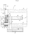
- Figure 2
- is a partially sectional plan view of a detail of the press in figure 1, enlarged with respect to figure 1; the columns of the press are drawn with a broken line;
- Figure 3
- is a sectional view along 3-3 in figure 1;
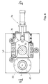
- Figure 4
- is a sectional view along 4-4 in figure 1, showing a further embodiment of locking means for the plunger foot;
- Figure 5
- is a sectional view along 5-5 in figure 4;
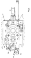
- Figure 6
- is a detailed view similar to figure 3, of a modified embodiment.
- An extrusion press, in particular a forward extrusion press, is illustrated in the drawings and referenced 10 as a whole. It comprises a fixed structure, which comprises four
horizontal columns 12 andvertical mounts container 16 of a well-known type, acutter 18 and a die holder slide 20 downstream of the container, these elements also being of a well-known type. Furthermore it comprises acylinder 22 and relativemain ram 24 for operating a plunger or extrusion stem, andside cylinders 26 for the return movement of the plunger. - The
cylinder 22,ram 24, container cavity (not shown) are aligned along extrusion axis a. - The
ram 24 acts on amobile cross member 28 which is movable longitudinally guided by thecolumns 12. - The mobile cross member or
beam 28 has ahole 30 which receives abush 32 in a rotatable way around an axis b parallel to said axis a. Thebush 32 is integral with acrown gear 34, engaging with arack 36 which is formed on abar 38 integral with the piston rod of acylinder 40. - The
cylinder 40 is carried on saidmovable cross member 28 and the rack has a movement which is transverse to the axis a. Thebush 32 is rotationally integral with rotation in any known way (for example by means of grooves and longitudinal projections) with apin 42. This can slide longitudinally for a length inside the bush and therefore with respect to thecross member 28, and revolves around the axis b. The sliding of the pin is effected by means of acylinder 44 integral with the cross member or integrated in the pin and having itsrod 45 integral with the pin. At the opposite end to thecylinder 44, the pin carries in an integral way atransverse arm 46 extending from one and the other part of the axis b. Such arm carries an extrusion stem orplunger 48 on one side of the axis b, and aloader 50 for the billet B on the other side. - The loader is drawn in the form of a cage, but obviously it can be of any shape as long as it allows the billet to come out axially.
- The
plunger 48 has ahead 52 of a well-known type and afoot 54 extending towards thecross member 28. This has a seat or thrustsurface 56 for the foot. It also has a throughopening 58 aligned along axis a for a low pressure piston orpusher 60 for loading a billet into the container. - A locking
device 62 may be provided for locking theplunger foot 54 onto theseat 28, e.g. a pin received in a through hole. - The
arm 46 in figures 1 - 3 is shown with the loader in position for receiving a billet, located outside the press and side by side with it; theplunger 48 is in the working position aligned on the axis a. A billet B is drawn in dash-dot lines, on theloader 50 and a billet B' is drawn in dash-dot lines in the position which it assumes when it is on the axis a. - The arm is shown as rectilinear in the drawings; in this way a rotation through 180° from the position illustrated in figure 3 transfers the billet B onto the axis a and the plunger to a rest or maintenance position on the same side of the press, where the billet has been loaded. A rotation through 180° in the opposite direction transfers the loader once more to the position for receiving the billet and the plunger onto the axis a. However
arm 28 could have an angular form, so that the transfer takes place through arcs of less than 180°. - Figures 4, 5 show a further embodiment of the press with a different locking device for the
plunger foot 54, referenced 70 as a whole. Lockingdevice 70 comprises a fork-like locking member 72, which is movable between a locking position (shown in figure 4) and an unlocking position (not shown) under control of a cylinder-piston unit 74 carried oncross member 28. - In the locking position, the arms of
member 72 engage a circumferential slot of saidfoot 54. - Figure 6 shows a further modified embodiment of the extrusion press (the same reference numbers refer to similar parts throughout the various figures) wherein a device is provided for an axial adjustment of the plunger, said device comprising four
radial screws 80 operating on a plunger carrying bush. In this way it is possible to compensate the plunger possible radial runouts due to the termal expansion . - In the same figure a
loader 150 is shown as comprising aninclined base 152 and anadjustable jaw 154; said jaw comprises a first member pivoted at 155 ontransverse arm 46 andsecond member 156, pivoted on the first member and locked to it at a selected angular position by per se known means 157. - Said adjustable jaw may be readily adjusted according to the diameter of the billet.
- A description of the process and press operation is given below.
- In the condition shown in the figures, the
loader 50 is in its rest or maintenance position outside the structure andplunger 48 is positioned along the axis a with itsfoot 54 resting against theseat 56, preferably locked by lockingdevice 62, or lockingdevice 70. -
Ram 24 drives cross member orbeam 28,arm 46 andplunger 48 for a working stroke (towards the right in figures 1, 2).Plunger 48 extrudes a billet (not shown), previously positioned in the container cavity, across an extrusion die in thedie holder 20. - When the plunger is at a position almost completely extended into the container, a billet B begins to be loaded onto the
loader 50, being transferred thereto from a carriage (not shown) moving parallel to axes a, b and at the same speed as the plunger. - Then a return stroke of
plunger 48,arm 46 andcross member 28 is operated throughside cylinders 26. -
Cylinder 44 moves thefoot 54 of the plunger away from the relative seat orhousing 56, in order to allowarm 46 to rotate. - The
cylinder 40 operatesrack 36 for rotatingarm 46, for example through 180° as already stated, thus bringing the plunger to the side of the press and the billet-carrying loader along axis a. - The small piston or
pusher 60 pushes the billet B into the container cavity while the operator can carry out necessary maintenance operations on the plunger. - A subsequent stroke of the
rod 38 of thecylinder 40, in the opposite direction to the previous stroke, rotates the pin through 180° in the opposite direction and brings back thearm 46 with the loader and the plunger into the position shown in the figures. - It should be noted that in the rest position the plunger is positioned on the same side of the press on which the billets are loaded.
Claims (10)
- An extrusion press comprising, on a fixed structure (12, 14, 15), a cross member (28) which is movable along a longitudinal or extrusion axis (a) of the press, a cylinder assembly (22) for driving the cross member; a container (16) having an axial cavity for receiving a billet to be extruded; a die holder slide (20)
characterized in that it also comprises
an arm (46) pivotally carried on the said cross member (28), said arm carrying a plunger (48) and a billet loader (50) spaced out from each other, the said arm (46) being rotatable between a condition in which it locates the plunger in a working position on the extrusion axis a of the press and the loader (50) in a position for receiving the billets on one side of the press, and a condition in which it locates the loader in a position on the extrusion axis (a) of the press and the plunger in a rest position on the said side of the press. - A press according to claim 1, characterized in that the said arm is rotatable around an axis (b) parallel with the extrusion axis (a) of the press.
- A press according to claim 1, characterized in that the said cross member (28) comprises a supporting seat (56) for a foot (54) of the plunger (48), the said seat being centred on the axis (a) of the press,
the said arm (46) being carried on the said cross member (28) and being longitudinally traversable for a short length thereon. - A press according to claim 3, characterized in that the said cross member further comprises a through hole (58) on the axis (a) and a small piston or pusher (60) cooperating with said hole for loading the billets in the container cavity.
- A press according to claim 3, characterized in that it comprises locking means (62; 70) for the foot of the plunger.
- A press as in claim 5, characterized in that said locking means comprise a pin cooperating with a through hole of said foot.
- A press as in claim 5, characterized in that said locking means comprise a fork-like member (72) engageable in a circumferential slot of the plunger foot.
- A press according to claim 1, characterized in that said transverse arm (46) is carried on a pin (42), which is axially slidable into but rotationally integral with a bush (32), said bush is in turn received in a rotatable manner in the mobile cross member (28), the bush being integral with a crown gear (34) which engages with a rack (36) carried on the cross member and movable on it in a direction transverse to the axis (a) of the press.
- A process for carrying out billet extrusion on a short-stroke extrusion press, comprising the following steps:a) positioning a billet (B) to be extruded along the extrusion axis (a) of the press, by means of a loader (50);b) pushing said billet into a container cavity by means of a pusher (60);c) extruding said billet by means of a plunger (48);d) loading a further billet (B) on said loader (50);a') positioning said further billet along the extrusion axis (a);
characterized by rotating a plunger-and-loader-carrying arm (46) between said steps b) and c) and between said steps d) and a'). - A process as in claim 9 characterized in that step c) and step d) are carried out simultaneously, while said plunger-and-loader-carrying arm (46) with its plunger and loader is advancing along the extrusion axis for carrying out extrusion of the first-mentioned billet, the further billet being loaded on said loader from a carriage moving in synchronism with it.
Applications Claiming Priority (2)
| Application Number | Priority Date | Filing Date | Title |
|---|---|---|---|
| ITMI912886 | 1991-10-30 | ||
| ITMI912886A IT1251746B (en) | 1991-10-30 | 1991-10-30 | QUICK LOADING EXTRUSION PRESS |
Publications (2)
| Publication Number | Publication Date |
|---|---|
| EP0539906A1 EP0539906A1 (en) | 1993-05-05 |
| EP0539906B1 true EP0539906B1 (en) | 1996-05-08 |
Family
ID=11360989
Family Applications (1)
| Application Number | Title | Priority Date | Filing Date |
|---|---|---|---|
| EP92118283A Expired - Lifetime EP0539906B1 (en) | 1991-10-30 | 1992-10-26 | Rapid loading short-stroke extrusion press, and process |
Country Status (8)
| Country | Link |
|---|---|
| US (1) | US5335528A (en) |
| EP (1) | EP0539906B1 (en) |
| JP (1) | JP3115712B2 (en) |
| AT (1) | ATE137692T1 (en) |
| CA (1) | CA2081137C (en) |
| DE (1) | DE69210538T2 (en) |
| ES (1) | ES2089339T3 (en) |
| IT (1) | IT1251746B (en) |
Families Citing this family (6)
| Publication number | Priority date | Publication date | Assignee | Title |
|---|---|---|---|---|
| DE4244261C2 (en) * | 1992-12-22 | 1995-05-11 | Mannesmann Ag | Working procedure for loading a press block and metal extrusion press for carrying out the working procedure |
| EP0672473A1 (en) * | 1994-03-15 | 1995-09-20 | Norsk Hydro A/S | Apparatus and process for the extrusion of profiles |
| IT1303025B1 (en) * | 1998-04-17 | 2000-10-20 | Demag Italimpianti Spa | SHORT STROKE DIRECT EXTRUSION PRESS IN WHICH THE BILLET FEEDER IS INTEGRATED ON THE SAME PRESS |
| DE10222951A1 (en) * | 2002-05-24 | 2003-12-04 | Sms Eumuco Gmbh | Metal extrusion press, especially horizontal metal extrusion press |
| JP4604997B2 (en) * | 2005-12-12 | 2011-01-05 | 宇部興産機械株式会社 | Stem slide device |
| KR101049629B1 (en) * | 2006-10-16 | 2011-07-14 | 우베 고산 기카이 가부시키가이샤 | Stem slide device |
Family Cites Families (9)
| Publication number | Priority date | Publication date | Assignee | Title |
|---|---|---|---|---|
| US2188076A (en) * | 1938-09-19 | 1940-01-23 | Watson Stillman Co | Extrusion press |
| US2751076A (en) * | 1953-02-16 | 1956-06-19 | Daniel L Lombard | Extrusion press installation |
| US3119493A (en) * | 1959-07-01 | 1964-01-28 | Schloemann Ag | Extrusion presses |
| GB1116936A (en) * | 1964-11-07 | 1968-06-12 | Hydraulik Gmbh | Improvements in or relating to extrusion presses |
| ES335193A1 (en) * | 1966-01-19 | 1967-12-01 | Kobe Steel Ltd | A metal extrusion press. (Machine-translation by Google Translate, not legally binding) |
| US4326399A (en) * | 1978-03-14 | 1982-04-27 | Secim | Extrusion press operating by the indirect method |
| US4342212A (en) * | 1980-09-02 | 1982-08-03 | Sutton Engineering Company | Indirect extrusion press |
| US4785652A (en) * | 1986-07-18 | 1988-11-22 | Stewart Charles L | Indirect extrusion press with ram-mounted turret supporting tooling |
| IT1197936B (en) * | 1986-10-31 | 1988-12-21 | Innocenti Santeustacchio Spa | HORIZONTAL EXTRUSION PRESS |
-
1991
- 1991-10-30 IT ITMI912886A patent/IT1251746B/en active IP Right Grant
-
1992
- 1992-10-22 CA CA002081137A patent/CA2081137C/en not_active Expired - Fee Related
- 1992-10-22 US US07/970,492 patent/US5335528A/en not_active Expired - Lifetime
- 1992-10-26 ES ES92118283T patent/ES2089339T3/en not_active Expired - Lifetime
- 1992-10-26 DE DE69210538T patent/DE69210538T2/en not_active Expired - Fee Related
- 1992-10-26 AT AT92118283T patent/ATE137692T1/en active
- 1992-10-26 EP EP92118283A patent/EP0539906B1/en not_active Expired - Lifetime
- 1992-10-30 JP JP04292525A patent/JP3115712B2/en not_active Expired - Fee Related
Also Published As
| Publication number | Publication date |
|---|---|
| ATE137692T1 (en) | 1996-05-15 |
| CA2081137C (en) | 2003-12-09 |
| JPH05237539A (en) | 1993-09-17 |
| ES2089339T3 (en) | 1996-10-01 |
| IT1251746B (en) | 1995-05-23 |
| ITMI912886A1 (en) | 1993-04-30 |
| DE69210538T2 (en) | 1996-11-28 |
| CA2081137A1 (en) | 1993-05-01 |
| EP0539906A1 (en) | 1993-05-05 |
| US5335528A (en) | 1994-08-09 |
| DE69210538D1 (en) | 1996-06-13 |
| ITMI912886A0 (en) | 1991-10-30 |
| JP3115712B2 (en) | 2000-12-11 |
Similar Documents
| Publication | Publication Date | Title |
|---|---|---|
| US4365497A (en) | Intermediate frame type indirect extrusion press | |
| JP3715725B2 (en) | Running interval cutting device in thin-walled tube continuous manufacturing equipment | |
| US4230661A (en) | Indirect extrusion process | |
| US3273433A (en) | Tubular stock cutoff method and apparatus | |
| US5335528A (en) | Rapid loading short-stroke extrusion press, and process | |
| US4126030A (en) | Retractable pressure die | |
| US2738063A (en) | Device for indexing the die apertures on extrusion presses | |
| RU2076007C1 (en) | Method of making articles by backward extrusion and apparatus for performing the same | |
| US1935286A (en) | Extrusion press for the production of rod or tube-shaped bodies | |
| WO2009008819A1 (en) | A system operable to extrude metallic materials | |
| US3875781A (en) | Press for producing closed-bottomed articles | |
| US4326399A (en) | Extrusion press operating by the indirect method | |
| US3780606A (en) | Hot log shear | |
| JP2514458B2 (en) | Extrusion press equipment | |
| US5247821A (en) | Extruding press and method for its feeding | |
| GB2035178A (en) | Apparatus for supporting workpieces on turning machines | |
| US4720990A (en) | Ejector mechanism for eccentric presses | |
| EP0316344B1 (en) | Indirect extrusion press with ram-mounted turret supporting tool | |
| US3651680A (en) | Tube press with mandrel adjustment | |
| RU2006325C1 (en) | Device for scalping billets | |
| JPH10225714A (en) | Extrusion molding method and apparatus using double-acting extrusion press | |
| US5657661A (en) | Working method for loading an extrusion billet and metal extrusion press | |
| JPH06269850A (en) | Double acting type direct extruding press using clean out disk | |
| JP2509692Y2 (en) | Free dies for indirect extrusion press | |
| JPH07100169B2 (en) | Extrusion press |
Legal Events
| Date | Code | Title | Description |
|---|---|---|---|
| PUAI | Public reference made under article 153(3) epc to a published international application that has entered the european phase |
Free format text: ORIGINAL CODE: 0009012 |
|
| AK | Designated contracting states |
Kind code of ref document: A1 Designated state(s): AT BE CH DE DK ES FR GB GR LI NL PT SE |
|
| 17P | Request for examination filed |
Effective date: 19930731 |
|
| 17Q | First examination report despatched |
Effective date: 19941227 |
|
| GRAH | Despatch of communication of intention to grant a patent |
Free format text: ORIGINAL CODE: EPIDOS IGRA |
|
| GRAA | (expected) grant |
Free format text: ORIGINAL CODE: 0009210 |
|
| AK | Designated contracting states |
Kind code of ref document: B1 Designated state(s): AT BE CH DE DK ES FR GB GR LI NL PT SE |
|
| PG25 | Lapsed in a contracting state [announced via postgrant information from national office to epo] |
Ref country code: LI Effective date: 19960508 Ref country code: GR Free format text: LAPSE BECAUSE OF FAILURE TO SUBMIT A TRANSLATION OF THE DESCRIPTION OR TO PAY THE FEE WITHIN THE PRESCRIBED TIME-LIMIT Effective date: 19960508 Ref country code: BE Effective date: 19960508 Ref country code: AT Effective date: 19960508 Ref country code: CH Effective date: 19960508 Ref country code: DK Effective date: 19960508 Ref country code: NL Free format text: LAPSE BECAUSE OF FAILURE TO SUBMIT A TRANSLATION OF THE DESCRIPTION OR TO PAY THE FEE WITHIN THE PRESCRIBED TIME-LIMIT Effective date: 19960508 |
|
| REF | Corresponds to: |
Ref document number: 137692 Country of ref document: AT Date of ref document: 19960515 Kind code of ref document: T |
|
| REF | Corresponds to: |
Ref document number: 69210538 Country of ref document: DE Date of ref document: 19960613 |
|
| PG25 | Lapsed in a contracting state [announced via postgrant information from national office to epo] |
Ref country code: SE Effective date: 19960808 Ref country code: PT Effective date: 19960808 |
|
| ET | Fr: translation filed | ||
| NLV1 | Nl: lapsed or annulled due to failure to fulfill the requirements of art. 29p and 29m of the patents act | ||
| REG | Reference to a national code |
Ref country code: ES Ref legal event code: FG2A Ref document number: 2089339 Country of ref document: ES Kind code of ref document: T3 |
|
| REG | Reference to a national code |
Ref country code: CH Ref legal event code: PL |
|
| REG | Reference to a national code |
Ref country code: ES Ref legal event code: FG2A Ref document number: 2089339 Country of ref document: ES Kind code of ref document: T3 |
|
| PLBE | No opposition filed within time limit |
Free format text: ORIGINAL CODE: 0009261 |
|
| STAA | Information on the status of an ep patent application or granted ep patent |
Free format text: STATUS: NO OPPOSITION FILED WITHIN TIME LIMIT |
|
| 26N | No opposition filed | ||
| REG | Reference to a national code |
Ref country code: GB Ref legal event code: IF02 |
|
| PGFP | Annual fee paid to national office [announced via postgrant information from national office to epo] |
Ref country code: DE Payment date: 20081027 Year of fee payment: 17 |
|
| PGFP | Annual fee paid to national office [announced via postgrant information from national office to epo] |
Ref country code: ES Payment date: 20081121 Year of fee payment: 17 |
|
| PGFP | Annual fee paid to national office [announced via postgrant information from national office to epo] |
Ref country code: FR Payment date: 20081014 Year of fee payment: 17 |
|
| PGFP | Annual fee paid to national office [announced via postgrant information from national office to epo] |
Ref country code: GB Payment date: 20081022 Year of fee payment: 17 |
|
| REG | Reference to a national code |
Ref country code: FR Ref legal event code: ST Effective date: 20100630 |
|
| PG25 | Lapsed in a contracting state [announced via postgrant information from national office to epo] |
Ref country code: DE Free format text: LAPSE BECAUSE OF NON-PAYMENT OF DUE FEES Effective date: 20100501 Ref country code: FR Free format text: LAPSE BECAUSE OF NON-PAYMENT OF DUE FEES Effective date: 20091102 |
|
| PG25 | Lapsed in a contracting state [announced via postgrant information from national office to epo] |
Ref country code: GB Free format text: LAPSE BECAUSE OF NON-PAYMENT OF DUE FEES Effective date: 20091026 |
|
| REG | Reference to a national code |
Ref country code: ES Ref legal event code: FD2A Effective date: 20110310 |
|
| PG25 | Lapsed in a contracting state [announced via postgrant information from national office to epo] |
Ref country code: ES Free format text: LAPSE BECAUSE OF NON-PAYMENT OF DUE FEES Effective date: 20110309 |
|
| PG25 | Lapsed in a contracting state [announced via postgrant information from national office to epo] |
Ref country code: ES Free format text: LAPSE BECAUSE OF NON-PAYMENT OF DUE FEES Effective date: 20091027 |