EP0539735A1 - Method and device for exposing moved containers to a laser beam - Google Patents
Method and device for exposing moved containers to a laser beam Download PDFInfo
- Publication number
- EP0539735A1 EP0539735A1 EP92116503A EP92116503A EP0539735A1 EP 0539735 A1 EP0539735 A1 EP 0539735A1 EP 92116503 A EP92116503 A EP 92116503A EP 92116503 A EP92116503 A EP 92116503A EP 0539735 A1 EP0539735 A1 EP 0539735A1
- Authority
- EP
- European Patent Office
- Prior art keywords
- mirror
- carousel
- bottle
- laser beam
- bottles
- Prior art date
- Legal status (The legal status is an assumption and is not a legal conclusion. Google has not performed a legal analysis and makes no representation as to the accuracy of the status listed.)
- Granted
Links
Images

Classifications
-
- B—PERFORMING OPERATIONS; TRANSPORTING
- B07—SEPARATING SOLIDS FROM SOLIDS; SORTING
- B07C—POSTAL SORTING; SORTING INDIVIDUAL ARTICLES, OR BULK MATERIAL FIT TO BE SORTED PIECE-MEAL, e.g. BY PICKING
- B07C5/00—Sorting according to a characteristic or feature of the articles or material being sorted, e.g. by control effected by devices which detect or measure such characteristic or feature; Sorting by manually actuated devices, e.g. switches
- B07C5/04—Sorting according to size
- B07C5/12—Sorting according to size characterised by the application to particular articles, not otherwise provided for
- B07C5/122—Sorting according to size characterised by the application to particular articles, not otherwise provided for for bottles, ampoules, jars and other glassware
-
- B—PERFORMING OPERATIONS; TRANSPORTING
- B07—SEPARATING SOLIDS FROM SOLIDS; SORTING
- B07C—POSTAL SORTING; SORTING INDIVIDUAL ARTICLES, OR BULK MATERIAL FIT TO BE SORTED PIECE-MEAL, e.g. BY PICKING
- B07C5/00—Sorting according to a characteristic or feature of the articles or material being sorted, e.g. by control effected by devices which detect or measure such characteristic or feature; Sorting by manually actuated devices, e.g. switches
- B07C5/34—Sorting according to other particular properties
- B07C5/3412—Sorting according to other particular properties according to a code applied to the object which indicates a property of the object, e.g. quality class, contents or incorrect indication
-
- G—PHYSICS
- G06—COMPUTING; CALCULATING OR COUNTING
- G06K—GRAPHICAL DATA READING; PRESENTATION OF DATA; RECORD CARRIERS; HANDLING RECORD CARRIERS
- G06K1/00—Methods or arrangements for marking the record carrier in digital fashion
- G06K1/12—Methods or arrangements for marking the record carrier in digital fashion otherwise than by punching
- G06K1/126—Methods or arrangements for marking the record carrier in digital fashion otherwise than by punching by photographic or thermographic registration
Definitions
- the invention relates to a method for loading containers moved by a conveyor system, in particular PET bottles, with at least one laser beam for inspecting and / or processing the containers, in particular for applying at least one code symbol.
- the invention further relates to an inspection machine for bottles for carrying out the method.
- the inspection includes, in particular, checking the bottle for damage and / or reading one or more code symbols present on the bottle. As a rule, the inspection machine applies at least one further code symbol. This application or melting of the code symbol and, if appropriate, the reading of code symbols take place by means of at least one laser beam, which is generally directed onto the bottle at a desired, predetermined point. Damage can also be checked using laser beams.
- the object of the invention is therefore to process and / or measure or inspect containers, but in particular PET bottles, as they pass through the inspection machine using a laser beam, this being done with the highest possible cadence and productivity.
- This object is achieved in a method of the type mentioned at the outset in that the laser beam is guided over an arrangement of mirrors which are fixed and / or movable with respect to the conveyor system, in order to move in a synchronized manner with the container during at least one section of the conveyor path .
- the method is preferably used in an inspection machine for bottles, in particular PET bottles, which has a corresponding conveying device.
- the inspection machine is preferably designed as a carousel machine.
- the beam is preferably coupled exactly into the carousel axis, so it can be deflected radially by a mirror fixedly mounted in this axis and always moves synchronously with the carousel.
- a preferred structure can look like this:
- the laser is firmly mounted on the machine so that the standard first deflecting mirror deflects the beam centrally into the carousel axis designed as a hollow shaft.
- the mask Inside the hollow shaft there is the mask in the beam path and below it a second deflecting mirror that radially deflects the beam at 90 °. If this deflecting mirror is firmly mounted on the axis, the laser beam will maintain a constant position with respect to the carousel axis, regardless of the speed of rotation of the carousel.
- a lens or a parabolic mirror can be arranged immediately behind the second mirror in order to image the mask on the bottle.
- This arrangement is expediently supplemented by a further deflecting mirror in relation to the bottle holder, with which the beam is finely positioned.
- FIGS. 3 to 5 show an inspection machine which is known per se and which will first be briefly explained for better understanding of the following exemplary embodiments of the invention.
- This special inspection machine is only shown as an example and for a better understanding of FIGS. 3 to 5; the invention can easily be applied to other inspection machines.
- the machine is generally designated 101 in FIG. 1. It has a frame 102 with an upper support plate 103 and a lower support plate 104, between which a carousel device, generally designated 106, is fastened.
- the carousel device 106 has a central carousel 108 with twelve receiving devices 110 for bottles 112 and two smaller carousels 114, 116, each with eight receiving devices on.
- the carousel device 106 is part of a conveyor device with which the bottles 112 are moved into a detection station 130 for checking and reading codes and an identification station 140 for writing codes, which is described in more detail below.
- the two smaller carousels 114, 116 in conjunction with two screw conveyors 118, 120, convey the bottles 112 into and out of the device 101.
- a common drive system 122 is attached, which comprises a geared motor 124, which in detail Toothed belt pulleys and toothed belts, not specified, drives the carousel device 106 and the screw conveyors 118, 120.
- the central carousel 108 consists of an upper main carousel 108a, a central main carousel 108b and a lower main carousel 108c, which are fastened on a common shaft 109.
- the receiving devices 110 consist of twelve recesses semicircular in cross-section on the central main carousel 108b, twelve heads 126 provided on the upper main carousel 108a (only two are visible in FIG. 1) and twelve rotatable seats 128 provided on the lower main carousel 108c for receiving, clamping or placing the bottles 112. Each head 126 is fastened to the upper main carousel 108a in a vertically movable manner with a curved track.
- the course or the shape of the curved path is selected such that the head 126 is arranged in the area of the carousel 114 at a distance above the bottle mouth, that during the movement of the bottle 112 into the detection station 130 the bottle mouth is lowered and at least until the bottle mouth is reached Marking station 140 remains lowered and is finally raised again from the bottle and moved back to its original height at which it is at a distance from the bottle mouth.
- the bottle 112 After the bottle 112 has passed the screw conveyor 118 and the carousel 114 at the inlet of the device, it is clamped vertically in the holding devices 110 of the central carousel 108 by lowering the head 126. After clamping, some time is available to let vibrations subside. Then the bottle 112 passes the detection station 130, where the bottle is inspected and a code already on the bottle is read. This information is transmitted to a main controller and from here to a carousel microcontroller. The carousel microcontroller drives the stepper motors 158 to place the bottle 112 in the position where it can be identified with a new code symbol. After the new code symbol has been applied, the bottle is released by lifting the head 126. The carousel 116 and the screw conveyor 120 at the outlet of the device 101 convey the bottle 112 out of the device 101.
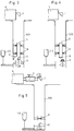
- FIG. 3 shows schematically a part of the carousel with the axis 109 of the carousel designed as a hollow shaft and only one bottle 112 shown in the carousel as an example, which rotates around the hollow shaft and which in the example shown is to be provided with a code.
- the beam is reflected exactly in the carousel axis by means of deflecting mirror 1.
- deflecting mirror 2 which is fixed centrally in the axis and remains directed at this point when the carousel is rotated.
- the laser 4 is firmly mounted on the machine, so that the first one available as standard Deflecting mirror 1 deflects the beam centrally into the carousel axis 109 designed as a hollow shaft.
- the mask 5 with the pattern of the code in the beam path and below it a second deflecting mirror 2 which deflects the beam radially by 90 °. If this deflecting mirror 2 is fixedly mounted on the axis or if the mirror is moved synchronously with the hollow shaft 109, the laser beam will maintain a constant position with respect to the carousel axis, regardless of the speed of rotation of the carousel.
- a lens or a parabolic mirror 6 can be arranged as a focusing mirror in order to image the mask on the bottle.
- the image of the mask is burned into the PET bottle material by the laser beam.
- This arrangement is expediently supplemented by a further deflecting mirror 3 opposite each bottle holder (pocket), where a window is also provided in the hollow shaft with which the beam is finely positioned.
- the mirror 2 or the beam guide 5, 2 and 6 is quickly positioned to the next window or deflecting mirror 3 in order to process the next bottle.
- the last deflecting mirrors 3 are fixedly positioned in the circumference of the hollow shaft, in this case the adjustability of two tilt angles is sufficient.
- the imaging optics After taking a bottle into the main carousel, it is set in constant rotation by the base plate. The imaging optics are positioned on this bottle and follow the movement of the carousel. A code can now be marked during the rotation. After completing the marking process, the optics must be positioned on the following bottle.
- the polygon 7 contains the same number of mirror surfaces as the number of bits in the coding. Each of these mirror surfaces deflects the beam that falls vertically into the carousel axis onto the coding surface of the bottle. Since the bottle moves with the carousel during coding (rotating), it is necessary to carry the beam with it.
- the polygon must rotate by the angle ⁇ p so that the next mirror surface offset by the angle ⁇ k is aligned.
- This speed ratio of carousel and polygon is independent of the speed.
- the coding pulses are thus aligned with the axis of rotation of the bottle, the distance between successive codes is then only dependent on the speed of the bottle itself.
- the polygon 7 in the described embodiment is a special case of polygons whose common characteristic is that their mirror surfaces are each offset by an equal angle, i.e. the mirror surfaces form tangents to a spiral. Optical inspections are also possible with such polygons. If the number of mirror surfaces is increased, a beam can be tracked quasi-continuously to an object on the carousel. The length of the tracking section is determined by the sum of the individual offset angles.
- FIG. 5 A further embodiment is shown in FIG. 5, the same reference numerals denoting the same components as above.
- the mask 5 is arranged between the laser 4 and the first mirror 1.
- the imaging optics 6 are fixed, while the mirrors 1 and 2 are moved synchronously with the bottle 112.
- the aim of this variant is the rotation of the beam relative to the mask and the rotation of the image to eliminate on the bottle. This eliminates the need to rotate the mask and lens with the carousel.
- the mask is mounted in front of the first deflecting mirror. With the first mirror, the mask image is rotated and deflected 90 °. The beam must be centered in the mirror axis of rotation. At a corresponding distance from the mask, the lens is located centrally in the beam or. Carousel axis fixed (only linear focus adjustment). A second deflecting mirror is rotatably mounted directly under the lens, which directs the focused beam onto the bottle.
- Angle change only set one axis of the lower deflecting mirror.
- the optics inside the hollow shaft are all in the center, best design for dust / water protection.
Abstract
Description
Die Erfindung betrifft ein Verfahren zur Beaufschlagung von durch eine Förderanlage bewegten Gebinden, insbesondere PET-Flaschen, mit mindestens einem Laserstrahl zur Inspektion und/oder Bearbeitung der Gebinde, insbesondere zur Aufbringung mindestens eines Codesymbols. Ferner betrifft die Erfindung eine Inspektionsmaschine für Flaschen zur Durchführung des Verfahrens.The invention relates to a method for loading containers moved by a conveyor system, in particular PET bottles, with at least one laser beam for inspecting and / or processing the containers, in particular for applying at least one code symbol. The invention further relates to an inspection machine for bottles for carrying out the method.
Es ist bekannt, Gebinde, insbesondere mehrfach verwendbare PET-Flaschen, in Inspektionsmaschinen zu inspizieren und auch mit einem Code zu versehen. Die Inspektion umfasst insbesondere die Prüfung der Flasche auf Beschädigungen und/oder das Lesen eines oder mehrerer an der Flasche vorhandener Codesymbole. In der Regel wird durch die Inspektionsmaschine mindestens ein weiteres Codesymbol aufgebracht. Diese Aufbringung bzw. Einschmelzung des Codesymbols und gegebenenfalls das Lesen von Codesymbolen erfolgen mittels mindestens eines Laserstrahls, der im allgemeinen an gewünschter, vorbestimmter Stelle auf die Flasche gerichtet wird. Auch die Prüfung auf Beschädigungen kann mittels Laserstrahlen erfolgen.It is known to inspect containers, in particular PET bottles that can be used repeatedly, in inspection machines and also to provide them with a code. The inspection includes, in particular, checking the bottle for damage and / or reading one or more code symbols present on the bottle. As a rule, the inspection machine applies at least one further code symbol. This application or melting of the code symbol and, if appropriate, the reading of code symbols take place by means of at least one laser beam, which is generally directed onto the bottle at a desired, predetermined point. Damage can also be checked using laser beams.
Derzeit bekannte Anlagen zur Inspektion und/oder Codierung von PET-Flaschen mit Laserstrahlung sind durch eine statische Strahlführung gekennzeichnet. Die zu bearbeitenden Teile werden so vor dem Strahl positioniert, dass die Codierfläche vom Strahl beaufschlagt wird. Dazu muss die Transportbewegung für die Dauer des Codiervorgangs unterbrochen werden oder die Codierung muss in kürzester Zeit vorgenommen werden. Die Nachteile dieser Konzeption liegen in den hohen Beschleunigungen und geringer Produktivität von Laser und Maschine.Currently known systems for the inspection and / or coding of PET bottles with laser radiation are characterized by a static beam guidance. The parts to be machined are positioned in front of the beam in such a way that the coding area is acted on by the beam. To do this, the transport movement must be interrupted for the duration of the coding process or the coding must be carried out in the shortest possible time. The disadvantages of this concept are the high accelerations and low productivity of the laser and machine.
Der Erfindung liegt deshalb die Aufgabe zugrunde, Gebinde, insbesondere aber PET-Flaschen, während des Durchlaufs durch die Inspektionsmaschine mittels eines Laserstrahls zu bearbeiten und/oder zu vermessen bzw. zu inspizieren, wobei dies mit möglichst hoher Kadenz und Produktivität erfolgen soll.The object of the invention is therefore to process and / or measure or inspect containers, but in particular PET bottles, as they pass through the inspection machine using a laser beam, this being done with the highest possible cadence and productivity.
Diese Aufgabe wird bei einem Verfahren der eingangs genannten Art dadurch gelöst, dass der Laserstrahl über eine Anordnung aus in bezug auf die Förderanlage feststehenden und/oder beweglichen Spiegeln geführt wird, um während mindestens eines Abschnittes des Förderweges synchron mit dem Gebinde bewegt dieses beaufschlagend zu verlaufen.This object is achieved in a method of the type mentioned at the outset in that the laser beam is guided over an arrangement of mirrors which are fixed and / or movable with respect to the conveyor system, in order to move in a synchronized manner with the container during at least one section of the conveyor path .
Vorzugsweise wird das Verfahren bei einer Inspektionsmaschine für Flaschen, insbesondere PET-Flaschen, verwendet, welche eine entsprechende Fördereinrichtung aufweist.The method is preferably used in an inspection machine for bottles, in particular PET bottles, which has a corresponding conveying device.
Bevorzugterweise ist die Inspektionsmaschine als Karussellmaschine ausgebildet.The inspection machine is preferably designed as a carousel machine.
Vorzugsweise wird der Strahl exakt in die Karussellachse eingekoppelt, so kann er durch einen in dieser Achse fest montierten Spiegel radial umgelenkt werden und bewegt sich stets synchron mit dem Karussell. Ein bevorzugter Aufbau kann wie folgt aussehen:The beam is preferably coupled exactly into the carousel axis, so it can be deflected radially by a mirror fixedly mounted in this axis and always moves synchronously with the carousel. A preferred structure can look like this:
Der Laser wird fest auf der Maschine montiert, so dass der standardmässig vorhandene erste Umlenkspiegel den Strahl zentrisch in die als Hohlwelle ausgeführte Karussellachse umlenkt.The laser is firmly mounted on the machine so that the standard first deflecting mirror deflects the beam centrally into the carousel axis designed as a hollow shaft.
Innerhalb der Hohlwelle befindet sich im Strahlengang die Maske und darunter ein zweiter Umlenkspiegel, der den Strahl in 90° radial ablenkt. Ist dieser Umlenkspiegel fest auf der Achse montiert, so wird der Laserstrahl eine konstante Position in bezug auf die Karussellachse einhalten, unabhängig von der Rotationsgeschwindigkeit des Karussells.Inside the hollow shaft there is the mask in the beam path and below it a second deflecting mirror that radially deflects the beam at 90 °. If this deflecting mirror is firmly mounted on the axis, the laser beam will maintain a constant position with respect to the carousel axis, regardless of the speed of rotation of the carousel.
Unmittelbar hinter dem zweiten Spiegel kann eine Linse oder ein Parabolspiegel angeordnet werden, um die Maske auf die Flasche abzubilden.A lens or a parabolic mirror can be arranged immediately behind the second mirror in order to image the mask on the bottle.
Sinnvollerweise wird diese Anordnung ergänzt durch je einen weiteren Umlenkspiegel gegenüber den Flaschenhaltern, mit dem die Feinpositionierung des Strahles erfolgt.This arrangement is expediently supplemented by a further deflecting mirror in relation to the bottle holder, with which the beam is finely positioned.
Im folgenden werden Ausführungsarten der Erfindung anhand der Zeichnungen näher erläutert. Dabei zeigt:
- Figur 1 eine Gesamtansicht einer Inspektionsmaschine;
Figur 2 eine vereinfachte Draufsicht auf das Karussell der Inspektionsmaschine nach Figur 1;Figur 3 eine schematische Teilansicht des Karussells einer erfindungsgemässen Inspektionsmaschine;Figur 4 eine weitere Ausführungsform der Erfindung; undFigur 5 eine weitere, ebenfalls nur schematisch und teilweise dargestellte Ausführungsform der Erfindung.
- Figure 1 is an overall view of an inspection machine;
- FIG. 2 shows a simplified top view of the carousel of the inspection machine according to FIG. 1;
- FIG. 3 shows a schematic partial view of the carousel of an inspection machine according to the invention;
- Figure 4 shows another embodiment of the invention; and
- Figure 5 shows another, also only schematically and partially shown embodiment of the invention.
In den Figuren 1 und 2 ist eine an sich bekannte Inspektionsmaschine gezeigt, welche zum besseren Verständnis der nachfolgenden Ausführungsbeispiele der Erfindung zunächst kurz erläutert werden soll. Diese spezielle Inspektionsmaschine ist aber lediglich als Beispiel und zum besseren Verständnis der Figuren 3 bis 5 dargestellt; die Erfindung kann ohne weiteres auch bei anderen Inspektionsmaschinen angewendet werden.1 and 2 show an inspection machine which is known per se and which will first be briefly explained for better understanding of the following exemplary embodiments of the invention. This special inspection machine is only shown as an example and for a better understanding of FIGS. 3 to 5; the invention can easily be applied to other inspection machines.
Die Maschine ist in der Fig. 1 insgesamt mit 101 bezeichnet. Sie weist ein Gestell 102 mit einer oberen Tragplatte 103 und einer unteren Tragplatte 104 auf, zwischen denen eine insgesamt mit 106 bezeichnete Karusselleinrichtung befestigt ist. Die Karusselleinrichtung 106 weist ein zentrales Karussell 108 mit zwölf Aufnahmeeinrichtungen 110 für Flaschen 112 sowie zwei kleinere Karussells 114, 116 mit jeweils acht Aufnahmeeinrichtungen auf. Die Karusselleinrichtung 106 ist Teil einer Fördereinrichtung, mit der die Flaschen 112 in eine Erfassungsstation 130 zur Prüfung und zum Codelesen und eine Kennzeichnungsstation 140 zum Codeschreiben bewegt werden, was weiter unten noch näher beschrieben ist. Die beiden kleineren Karussells 114, 116 fördern in Verbindung mit zwei Schneckenförderern 118, 120 die Flaschen 112 in die bzw. aus der Vorrichtung 101. Unter der unteren Tragplatte 104 ist ein gemeinsames Antriebssystem 122 befestigt, das einen Getriebemotor 124 umfasst, der über im einzelnen nicht näher bezeichnete Zahnriemenscheiben und Zahnriemen die Karusselleinrichtung 106 und die Schneckenförderer 118, 120 antreibt.The machine is generally designated 101 in FIG. 1. It has a
Das zentrale Karussell 108 besteht aus einem oberen Hauptkarussell 108a, einem mittleren Hauptkarussell 108b und einem unteren Hauptkarussell 108c, die auf einer gemeinsamen Welle 109 befestigt sind. Die Aufnahmeeinrichtungen 110 bestehen aus zwölf im Querschnitt halbkreisförmigen Ausnehmungen an dem mittleren Hauptkarussell 108b, zwölf an dem oberen Hauptkarussell 108a vorgesehenen Köpfen 126 (nur zwei sind in Fig. 1 sichtbar) und zwölf an dem unteren Hauptkarussell 108c vorgesehenen drehbaren Sitzen 128 zum Aufnehmen, Einspannen bzw. Aufsetzen der Flaschen 112. Jeder Kopf 126 ist an dem oberen Hauptkarussell 108a mit einer Kurvenbahn vertikal beweglich befestigt. Der Verlauf oder die form der Kurvenbahn ist so gewählt, dass der Kopf 126 im Bereich des Karussells 114 mit Abstand oberhalb der Flaschenmündung angeordnet ist, dass während der Bewegung der Flasche 112 in die Erfassungsstation 130 auf die Flaschenmündung abgesenkt wird und wenigstens bis zum Erreichen der Kennzeichnungsstation 140 abgesenkt bleibt und schliesslich wieder von der Flasche abgehoben und in seine ursprüngliche Höhe zurückbewegt wird, in der er Abstand von der Flaschenmündung hat.The
Die bis hierher beschriebene Vorrichtung zum Kennzeichnen von wiederbefüllbaren transparenten Flaschen arbeitet, kurz zusammengefasst, folgendermassen:The device for marking refillable transparent bottles described so far works, briefly summarized, as follows:
Nachdem die Flasche 112 am Einlass der Vorrichtung den Schneckförderer 118 und das Karussell 114 passiert hat, wird sie in den Aufnahmeeinrichtungen 110 des zentralen Karussells 108 vertikal eingespannt, indem der Kopf 126 abgesenkt wird. Nach dem Einspannen ist etwas Zeit verfügbar, um Schwingungen abklingen zu lassen. Dann passiert die Flasche 112 die Erfassungsstation 130, in der die Flasche inspiziert wird und ein bereits auf der Flasche befindlicher Code gelesen wird. Diese Information wird zu einem Hauptcontroller und von hier zu einem Karussellmikrocontroller übertragen. Der Karussellmikrocontroller steuert die Schrittmotoren 158 an, um die Flasche 112 in die Position zu bringen, in der sie mit einem neuen Codesymbol gekennzeichnet werden kann. Nach dem Aufbringen des neuen Codesymbols wird die Flasche gelöst, indem der Kopf 126 angehoben wird. Das Karussell 116 und der Schneckenförderer 120 am Auslass der Vorrichtung 101 befördern die Flasche 112 aus der Vorrichtung 101 hinaus.After the
Figur 3 zeigt nun schematisch einen Teil des Karussells mit der als Hohlwelle ausgebildeten Achse 109 des Karussells sowie nur eine beispielhaft dargestellt im Karussell befindliche Flasche 112, welche die Hohlwelle umläuft und welche im gezeigten Beispiel mit einem Code versehen werden soll.FIG. 3 shows schematically a part of the carousel with the
Der Strahl wird mittels Umlenkspiegel 1 exakt in die Karussellachse eingespiegelt. So kann er durch einen, zentrisch in der Achse fest montierten Umlenkspiegel 2 radial auf einen beliebigen Punkt auf dem Karussellumfang abgelenkt werden und bleibt bei der Drehung des Karussels auf diesen Punkt gerichtet.The beam is reflected exactly in the carousel axis by means of deflecting mirror 1. Thus, it can be deflected radially to an arbitrary point on the carousel circumference by a
Der Laser 4 wird fest auf der Maschine montiert, so dass der standardmässig vorhandene erste Umlenkspiegel 1 den Strahl zentrisch in die als Hohlwelle ausgeführte Karussellachse 109 umlenkt.The
Innerhalb der Hohlwelle befindet sich im Strahlengang die Maske 5 mit dem Muster des Codes und darunter ein zweiter Umlenkspiegel 2, der den Strahl um 90° radial ablenkt. Ist dieser Umlenkspiegel 2 fest auf der Achse montiert bzw. wird der Spiegel synchron zur Hohlwelle 109 bewegt, so wird der Laserstrahl eine konstante Position in bezug auf die Karussellachse einhalten, unabhängig von der Rotationsgeschwindigkeit des Karussells.Within the hollow shaft there is the
Unmittelbar hinter dem zweiten Spiegel kann eine Linse oder ein Parabolspiegel 6 als Fokussierspiegel angeordnet werden, um die Maske auf die Flasche abzubilden. Durch den Laserstrahl wird das Abbild der Maske in das PET-Flaschenmaterial eingebrannt.Immediately behind the second mirror, a lens or a
Sinnvollerweise wird diese Anordnung ergänzt durch je einen weiteren Umlenkspiegel 3 gegenüber jedem Flaschenhalter (Pocket), wo auch jeweils ein Fenster in der Hohlwelle vorgesehen ist, mit dem die Feinpositionierung des Strahles erfolgt. Nach der Bearbeitung einer Flasche wird der Spiegel 2 bzw. die Strahlführung 5, 2 und 6 rasch zum nächsten Fenster bzw. Umlenkspiegel 3 positioniert, um die nächste Flasche zu bearbeiten.This arrangement is expediently supplemented by a further deflecting
Für die einwandfreie Funktion ist es notwendig, den Strahl in den mit Positionstoleranzen behafteten Aufbau optisch zu justieren. Dies kann auch Erweiterungen der Strahlführung mit zusätzlichen, vorgeschalteten Umlenkspiegeln beinhalten. Die rotierend in der Karussellachse angeordneten Elemente: Maskenhalter 5, Umlenkspiegel 2, Fokussieroptik 6 befinden sich in fixen Positionen zueinander und werden vorteilhaft in einer vorjustierten Baugruppe zusammengefasst und zentriert auf einen in der Karussellachse befindlichen Lagerring 8 montiert. Lediglich die Fokuslage muss einstellbar sein zur Feineinstellung der Schärfe der Abbildung.For perfect function, it is necessary to optically adjust the beam in the structure that is subject to position tolerances. This can also include extensions of the beam guidance with additional upstream deflecting mirrors. The rotating elements in the carousel axis:
Die letzen Umlenkspiegel 3 werden fix in den Umfang der Hohlwelle positioniert, hierbei genügt die Einstellbarkeit von zwei Kippwinkeln.The last deflecting mirrors 3 are fixedly positioned in the circumference of the hollow shaft, in this case the adjustability of two tilt angles is sufficient.
Nach Uebernahme einer Flasche ins Hauptkarussell wird sie durch den Bodenteller in konstante Rotation versetzt. Die Abbildungsoptik ist auf diese Flasche positioniert und folgt der Bewegung des Karussels. Es kann nun während der Drehung ein Code markiert werden. Nach Abschluss des Markiervorgangs muss die Optik auf die folgende Flasche positioniert werden.After taking a bottle into the main carousel, it is set in constant rotation by the base plate. The imaging optics are positioned on this bottle and follow the movement of the carousel. A code can now be marked during the rotation. After completing the marking process, the optics must be positioned on the following bottle.
Der offensichtliche Nachteil dieses Aufbaus, dass mit der Optik schnelle reversierende Drehbewegungen ausgeführt werden müssen, kann durch Verwendung eines Polygonspiegels 7 umgangen werden, wie in Figur 4 gezeigt. Dieser stellt vorteilhaft die letzte Umlenkeinheit der Strahlführung dar und wird direkt unter die Fokussieroptik montiert, so dass die Spiegelflächen im axial zentrierten Strahl liegen.The obvious disadvantage of this structure, that fast reversing rotary movements have to be carried out with the optics, can be avoided by using a
Das Polygon 7 enthält die gleiche Anzahl Spiegelflächen wie die Bitzahl der Codierung. Durch jede dieser Spiegelflächen wird der vertikal in die Karussellachse einfallende Strahl auf die Codierfläche der Flasche umgelenkt. Da sich die Flasche während der Codierung (drehend) mit dem Karussell weiterbewegt, ist es nötig den Strahl mitzuführen.The
Das erfordert zunächst für den gepulst ablaufenden Codiervorgang, dass die Spiegelsegmente stets mittig getroffen werden, d.h. dass die Pulsfrequenz des Lasers über die Drehzahl des Polygons getriggert wird nach
mit
wobei
- f
- Pulsfrequenz,
- ωp
- Winkelgeschwindigkeit des Polygons,
- φ p (φk)
- Drehwinkel in der Zeit t,
- n
- Anzahl der Spiegelflächen.
With
in which
- f
- Pulse rate,
- ωp
- Angular velocity of the polygon,
- φ p (φ k )
- Angle of rotation in time t,
- n
- Number of mirror surfaces.
Dreht sich das Karussell in der Zeit t um einen Winkel φk, so muss sich das Polygon um den Winkel φp drehen, damit die nächste, um den Winkel φk versetzte Spiegelfläche ausgerichtet ist. Dieses Drehzahlverhältnis von Karussell und Polygon ist unabhängig von der Geschwindigkeit. Die Codierpulse sind somit auf die Drehachse der Flasche ausgerichtet, der Abstand aufeinander folgender Codes ist dann nur von der Drehzahl der Flasche selbst abhängig.If the carousel rotates by an angle φ k in time t, the polygon must rotate by the angle φ p so that the next mirror surface offset by the angle φ k is aligned. This speed ratio of carousel and polygon is independent of the speed. The coding pulses are thus aligned with the axis of rotation of the bottle, the distance between successive codes is then only dependent on the speed of the bottle itself.
Das Polygon 7 ist in der beschriebenen Ausführung ein Spzialfall von Polygonen, deren gemeinsames Kennzeichen ist, dass ihre Spiegelflächen jeweils um einen gleichen Winkel versetzt sind, d.h. die Spiegelflächen bilden Tangenten an eine Spirale. Mit solchen Polygonen sind auch optische Inspektionen möglich. Wird die Anzahl der Spiegelflächen erhöht, so kann ein Strahl einem auf dem Karussell befindlichen Objekt quasikontinuierlich nachgeführt werden. Die Länge der Nachführstrecke ist durch die Summe der einzelnen Versatzwinkel festgelegt.The
Für Laserstrahlen grösseren Durchmessers (Codieren) sind plane Spiegelflächen notwendig, da es sonst zu einer Bildverzerrung kommt. Dagegen kann ein sphärischer Anschliff bei Einsatz von Strahlen kleinen Durchmessers notwendig werden, wenn hohe Anforderungen an die Positioniergenauigkeit gestellt werden und die Anzahl der Spiegelflächen begrenzt werden soll.Flat mirror surfaces are necessary for laser beams of larger diameter (coding), since otherwise image distortion occurs. On the other hand, spherical grinding may be necessary when using beams of small diameter if high demands are placed on the positioning accuracy and the number of mirror surfaces is to be limited.
Eine weitere Ausführungsart ist in Figur 5 gezeigt, wobei gleiche Bezugsziffern gleiche Bauteile wie vorstehend bezeichnen. Bei diesem Beispiel ist die Maske 5 zwischen dem Laser 4 und dem ersten Spiegel 1 angeordnet. Die Abbildungsoptik 6 ist feststehend, während die Spiegel 1 und 2 synchron mit der Flasche 112 bewegt werden.A further embodiment is shown in FIG. 5, the same reference numerals denoting the same components as above. In this example, the
Ziel dieser Variante ist es, die Drehung des Strahles relativ zur Maske und die Drehung der Abbildung auf der Flasche zu eliminieren. Damit entfällt die Notwendigkeit Maske und Linse mit dem Karussell zu drehen.The aim of this variant is the rotation of the beam relative to the mask and the rotation of the image to eliminate on the bottle. This eliminates the need to rotate the mask and lens with the carousel.
Dazu wird die Maske vor dem ersten Umlenkspiegel montiert. Mit dem ersten Spiegel wird das Maskenbild gedreht und 90° umgelenkt. Der Strahl muss in der Spiegeldrehachse zentriert werden. In entsprechendem Abstand zur Maske befindet sich die Linse zentrisch im Strahl-/bzw. Karussellachse fest montiert (lediglich lineare Fokussierverstellung). Direkt unter der Linse ist ein zweiter Umlenkspiegel drehbar montiert, der den fokussierten Strahl auf die Flasche lenkt.To do this, the mask is mounted in front of the first deflecting mirror. With the first mirror, the mask image is rotated and deflected 90 °. The beam must be centered in the mirror axis of rotation. At a corresponding distance from the mask, the lens is located centrally in the beam or. Carousel axis fixed (only linear focus adjustment). A second deflecting mirror is rotatably mounted directly under the lens, which directs the focused beam onto the bottle.
Beide Umlenkspiegel müssen synchron stets die gleichen Drehbewegungen ausführen und in der Karussellachse montiert sein. Die Drehung besteht aus
- 1. Drehung mit Karussellgeschwindigkeit über einen Winkel entsprechend Pocketteilung;
- 2. Schnelle Rückstellbewegung (ohne Laserbetrieb).
- 1. Rotation at carousel speed over an angle corresponding to the pocket division;
- 2. Fast return movement (without laser operation).
Vorteilhaft bei dieser Anordnung ist, dass lediglich zwei Spiegel bewegt werden müssen, und daher recht hohe Durchlaufgeschwindigkeiten erreicht werden.The advantage of this arrangement is that only two mirrors have to be moved, and therefore very high throughput speeds are achieved.
Das Einstellen auf andere Flaschentypen (Winkel- und Abstandsänderungen) kann einfach durchgeführt werden.The adjustment to other bottle types (changes in angle and distance) can be carried out easily.
Winkeländerung: nur eine Achse des unteren Umlenkspiegels einstellen.Angle change: only set one axis of the lower deflecting mirror.
Distanzänderungen: nur lineare Verstellung von Maske, Linse und unterem Spiegel.Distance changes: only linear adjustment of mask, lens and lower mirror.
Zugänglichkeit, Einstellbarkeit sind besser als bei den ersten zwei Varianten. Die Optiken innerhalb der Hohlwelle befinden sich alle im Zentrum, beste Auslegung für Staub/Wasserschutz.Accessibility, adjustability are better than with the first two variants. The optics inside the hollow shaft are all in the center, best design for dust / water protection.
Claims (8)
Applications Claiming Priority (2)
| Application Number | Priority Date | Filing Date | Title |
|---|---|---|---|
| CH3199/91 | 1991-11-01 | ||
| CH3199/91A CH683288A5 (en) | 1991-11-01 | 1991-11-01 | Process and apparatus for subjecting moving containers with a laser beam. |
Publications (2)
| Publication Number | Publication Date |
|---|---|
| EP0539735A1 true EP0539735A1 (en) | 1993-05-05 |
| EP0539735B1 EP0539735B1 (en) | 1996-03-06 |
Family
ID=4250800
Family Applications (1)
| Application Number | Title | Priority Date | Filing Date |
|---|---|---|---|
| EP92116503A Expired - Lifetime EP0539735B1 (en) | 1991-11-01 | 1992-09-26 | Method and device for exposing moved containers to a laser beam |
Country Status (6)
| Country | Link |
|---|---|
| US (1) | US5315108A (en) |
| EP (1) | EP0539735B1 (en) |
| AT (1) | ATE134909T1 (en) |
| CH (1) | CH683288A5 (en) |
| DE (1) | DE59205574D1 (en) |
| MX (1) | MX9206266A (en) |
Cited By (7)
| Publication number | Priority date | Publication date | Assignee | Title |
|---|---|---|---|---|
| DE4314396A1 (en) * | 1993-04-30 | 1994-11-03 | Robert Prof Dr Ing Massen | Optical sorting of plastics |
| US5794788A (en) * | 1993-04-30 | 1998-08-18 | Massen; Robert | Method and device for sorting materials |
| EP1036495A1 (en) | 1999-03-17 | 2000-09-20 | Deere & Company | Crop divider |
| EP1295523A1 (en) | 2001-09-22 | 2003-03-26 | Deere & Company | Crop divider |
| DE102008028376A1 (en) | 2008-06-13 | 2009-12-17 | Krones Ag | Apparatus and method for marking plastic containers |
| WO2014161643A1 (en) * | 2013-04-03 | 2014-10-09 | Khs Gmbh | Conveyor system for container processing machines |
| EP2792605A1 (en) * | 2013-04-15 | 2014-10-22 | Krones AG | Table for container treatment machines |
Families Citing this family (12)
| Publication number | Priority date | Publication date | Assignee | Title |
|---|---|---|---|---|
| US5755335A (en) * | 1995-07-26 | 1998-05-26 | Steinmetz Machine Works, Inc. | Apparatus and method for centralized indexed inspection and rejection of products |
| DE19736732A1 (en) * | 1997-08-22 | 1999-03-11 | Lzh Laserzentrum Hannover Ev | Device and method for processing a workpiece by means of electromagnetic radiation and a mirror for reflecting electromagnetic radiation, in particular laser light |
| US6926487B1 (en) | 1998-04-28 | 2005-08-09 | Rexam Ab | Method and apparatus for manufacturing marked articles to be included in cans |
| US6080958A (en) | 1998-07-16 | 2000-06-27 | Ball Corporation | Method and apparatus for marking containers using laser light |
| US6706995B2 (en) * | 1998-07-16 | 2004-03-16 | Ball Corporation | Laser light marking of a container portion |
| WO2000035678A1 (en) * | 1998-12-16 | 2000-06-22 | The Domino Corporation | Method and apparatus for producing marks and codes on pet packaging |
| US6809288B2 (en) * | 2001-05-23 | 2004-10-26 | Osmotica Corp. | Laser drilling system and method |
| EP1295818B1 (en) * | 2001-09-20 | 2006-01-25 | Sig Simonazzi S.P.A. | Bottle-conveyor with top mounted drives |
| US7067323B2 (en) * | 2003-10-15 | 2006-06-27 | Lighthouse Instruments, Llc | System and method for automated headspace analysis |
| DE102008030868A1 (en) * | 2008-06-30 | 2009-12-31 | Krones Ag | Device for labeling containers |
| RU2670129C1 (en) | 2015-04-17 | 2018-10-18 | Бол Корпорейшн | Method and device for controlling speed of continuous sheet material |
| US10421111B2 (en) | 2015-04-17 | 2019-09-24 | Ball Corporation | Method and apparatus for controlling an operation performed on a continuous sheet of material |
Citations (5)
| Publication number | Priority date | Publication date | Assignee | Title |
|---|---|---|---|---|
| FR2234613A1 (en) * | 1973-06-21 | 1975-01-17 | Platmanufaktur Ab | |
| FR2270018A1 (en) * | 1974-05-06 | 1975-12-05 | Powers Manufacturing | |
| GB2134449A (en) * | 1983-02-01 | 1984-08-15 | Laserprint | Laser printing apparatus |
| EP0354362A2 (en) * | 1988-08-09 | 1990-02-14 | Elpatronic Ag | Method of marking a bottle with, and optically reading, readable codes |
| US4967070A (en) * | 1989-07-19 | 1990-10-30 | Owens-Brockway Glass Container Inc. | Indentification of a molded container with its mold of origin |
Family Cites Families (1)
| Publication number | Priority date | Publication date | Assignee | Title |
|---|---|---|---|---|
| FR2558259B1 (en) * | 1984-01-17 | 1986-12-12 | Saint Gobain Cinematique Contr | SCANNING TRANSMITTER FOR OPTICAL INSPECTION OF TRANSPARENT ITEMS |
-
1991
- 1991-11-01 CH CH3199/91A patent/CH683288A5/en not_active IP Right Cessation
-
1992
- 1992-09-26 AT AT92116503T patent/ATE134909T1/en not_active IP Right Cessation
- 1992-09-26 DE DE59205574T patent/DE59205574D1/en not_active Expired - Fee Related
- 1992-09-26 EP EP92116503A patent/EP0539735B1/en not_active Expired - Lifetime
- 1992-10-15 US US07/962,317 patent/US5315108A/en not_active Expired - Fee Related
- 1992-10-30 MX MX9206266A patent/MX9206266A/en unknown
Patent Citations (5)
| Publication number | Priority date | Publication date | Assignee | Title |
|---|---|---|---|---|
| FR2234613A1 (en) * | 1973-06-21 | 1975-01-17 | Platmanufaktur Ab | |
| FR2270018A1 (en) * | 1974-05-06 | 1975-12-05 | Powers Manufacturing | |
| GB2134449A (en) * | 1983-02-01 | 1984-08-15 | Laserprint | Laser printing apparatus |
| EP0354362A2 (en) * | 1988-08-09 | 1990-02-14 | Elpatronic Ag | Method of marking a bottle with, and optically reading, readable codes |
| US4967070A (en) * | 1989-07-19 | 1990-10-30 | Owens-Brockway Glass Container Inc. | Indentification of a molded container with its mold of origin |
Cited By (10)
| Publication number | Priority date | Publication date | Assignee | Title |
|---|---|---|---|---|
| DE4314396A1 (en) * | 1993-04-30 | 1994-11-03 | Robert Prof Dr Ing Massen | Optical sorting of plastics |
| US5794788A (en) * | 1993-04-30 | 1998-08-18 | Massen; Robert | Method and device for sorting materials |
| EP1036495A1 (en) | 1999-03-17 | 2000-09-20 | Deere & Company | Crop divider |
| EP1295523A1 (en) | 2001-09-22 | 2003-03-26 | Deere & Company | Crop divider |
| DE102008028376A1 (en) | 2008-06-13 | 2009-12-17 | Krones Ag | Apparatus and method for marking plastic containers |
| US8677721B2 (en) | 2008-06-13 | 2014-03-25 | Krones Ag | Apparatus and method for marking plastic containers |
| WO2014161643A1 (en) * | 2013-04-03 | 2014-10-09 | Khs Gmbh | Conveyor system for container processing machines |
| US9694988B2 (en) | 2013-04-03 | 2017-07-04 | Khs Gmbh | Conveyor system for container processing machines |
| EP2792605A1 (en) * | 2013-04-15 | 2014-10-22 | Krones AG | Table for container treatment machines |
| EP2792604A1 (en) * | 2013-04-15 | 2014-10-22 | Krones AG | Container handling machine |
Also Published As
| Publication number | Publication date |
|---|---|
| CH683288A5 (en) | 1994-02-15 |
| ATE134909T1 (en) | 1996-03-15 |
| MX9206266A (en) | 1993-08-01 |
| US5315108A (en) | 1994-05-24 |
| DE59205574D1 (en) | 1996-04-11 |
| EP0539735B1 (en) | 1996-03-06 |
Similar Documents
| Publication | Publication Date | Title |
|---|---|---|
| EP0539735B1 (en) | Method and device for exposing moved containers to a laser beam | |
| DE2429160C2 (en) | Method and device for identifying machine-formed molded articles | |
| EP1553405B1 (en) | Inspecting machine | |
| DE2725756C2 (en) | ||
| EP0135851B1 (en) | Process and device for marking parts, especially electronic components | |
| EP0228500B1 (en) | Method of and device for contactless measurement of the wheel profile of the wheels of railway wheel sets | |
| DE10146820B4 (en) | Decorating device and method for decorating surfaces | |
| DE2014448C3 (en) | Device for treating work pieces by means of laser energy | |
| DE2256736A1 (en) | METHOD FOR AUTOMATIC SURFACE PROFILE MEASUREMENT AND DEVICE FOR PERFORMING THE METHOD | |
| EP0682991A2 (en) | Automatic machine for sorting, respectively classifying small products from pharmaceutical and candy industry according to shape and colour | |
| EP0284921A1 (en) | Optical rays directing device | |
| EP1804055A1 (en) | Device for inspecting labels on containers | |
| DE60224623T2 (en) | Wall thickness measurement of a transparent container with a light fan | |
| DE2338295C2 (en) | Apparatus for detecting defects on opposing surfaces of a substantially flat path | |
| DE4313796A1 (en) | LASER MACHINING DEVICE | |
| EP0287018B1 (en) | Labelling device using print checking means | |
| DE102017218814B4 (en) | Labeling device and method for labeling a workpiece | |
| EP0041660A1 (en) | Reading and writting device comprising an optical scanning device | |
| EP1135709B1 (en) | Device for scanning an object | |
| DE3307484C2 (en) | Optical-mechanical scanner | |
| DE1135201B (en) | Control device for the detection of foreign bodies in a translucent container with means for illuminating a zone of the container to be controlled | |
| DE3242002C2 (en) | ||
| DE3220948A1 (en) | SCANNER DEVICE | |
| DE3022365A1 (en) | Optical scanner using rotating mirror - has narrow cylindrical surface on rotor and equally-spaced flat facets | |
| DE2262485A1 (en) | LIGHT SET |
Legal Events
| Date | Code | Title | Description |
|---|---|---|---|
| PUAI | Public reference made under article 153(3) epc to a published international application that has entered the european phase |
Free format text: ORIGINAL CODE: 0009012 |
|
| 17P | Request for examination filed |
Effective date: 19930123 |
|
| AK | Designated contracting states |
Kind code of ref document: A1 Designated state(s): AT DE NL SE |
|
| 17Q | First examination report despatched |
Effective date: 19941125 |
|
| RAP1 | Party data changed (applicant data changed or rights of an application transferred) |
Owner name: ELPATRONIC AG |
|
| GRAA | (expected) grant |
Free format text: ORIGINAL CODE: 0009210 |
|
| AK | Designated contracting states |
Kind code of ref document: B1 Designated state(s): AT DE NL SE |
|
| REF | Corresponds to: |
Ref document number: 134909 Country of ref document: AT Date of ref document: 19960315 Kind code of ref document: T |
|
| REF | Corresponds to: |
Ref document number: 59205574 Country of ref document: DE Date of ref document: 19960411 |
|
| PG25 | Lapsed in a contracting state [announced via postgrant information from national office to epo] |
Ref country code: AT Effective date: 19960926 |
|
| PLBE | No opposition filed within time limit |
Free format text: ORIGINAL CODE: 0009261 |
|
| STAA | Information on the status of an ep patent application or granted ep patent |
Free format text: STATUS: NO OPPOSITION FILED WITHIN TIME LIMIT |
|
| 26N | No opposition filed | ||
| PGFP | Annual fee paid to national office [announced via postgrant information from national office to epo] |
Ref country code: DE Payment date: 19970919 Year of fee payment: 6 |
|
| PGFP | Annual fee paid to national office [announced via postgrant information from national office to epo] |
Ref country code: SE Payment date: 19970925 Year of fee payment: 6 |
|
| PGFP | Annual fee paid to national office [announced via postgrant information from national office to epo] |
Ref country code: NL Payment date: 19970929 Year of fee payment: 6 |
|
| PG25 | Lapsed in a contracting state [announced via postgrant information from national office to epo] |
Ref country code: SE Free format text: LAPSE BECAUSE OF NON-PAYMENT OF DUE FEES Effective date: 19980927 |
|
| PG25 | Lapsed in a contracting state [announced via postgrant information from national office to epo] |
Ref country code: NL Free format text: LAPSE BECAUSE OF NON-PAYMENT OF DUE FEES Effective date: 19990401 |
|
| EUG | Se: european patent has lapsed |
Ref document number: 92116503.1 |
|
| NLV4 | Nl: lapsed or anulled due to non-payment of the annual fee |
Effective date: 19990401 |
|
| PG25 | Lapsed in a contracting state [announced via postgrant information from national office to epo] |
Ref country code: DE Free format text: LAPSE BECAUSE OF NON-PAYMENT OF DUE FEES Effective date: 19990701 |