EP0539340B1 - Launching system for a submunition - Google Patents
Launching system for a submunition Download PDFInfo
- Publication number
- EP0539340B1 EP0539340B1 EP92850238A EP92850238A EP0539340B1 EP 0539340 B1 EP0539340 B1 EP 0539340B1 EP 92850238 A EP92850238 A EP 92850238A EP 92850238 A EP92850238 A EP 92850238A EP 0539340 B1 EP0539340 B1 EP 0539340B1
- Authority
- EP
- European Patent Office
- Prior art keywords
- sub
- canister
- combat unit
- protective
- combat
- Prior art date
- Legal status (The legal status is an assumption and is not a legal conclusion. Google has not performed a legal analysis and makes no representation as to the accuracy of the status listed.)
- Expired - Lifetime
Links
- 230000001681 protective effect Effects 0.000 claims abstract description 42
- 238000000034 method Methods 0.000 claims abstract description 8
- 238000002485 combustion reaction Methods 0.000 claims description 7
- 238000006073 displacement reaction Methods 0.000 claims description 5
- 230000009172 bursting Effects 0.000 claims description 4
- 230000036461 convulsion Effects 0.000 claims description 2
- 238000007599 discharging Methods 0.000 claims description 2
- 238000000926 separation method Methods 0.000 description 8
- 239000000843 powder Substances 0.000 description 4
- 239000007789 gas Substances 0.000 description 3
- 230000004913 activation Effects 0.000 description 1
- 238000004200 deflagration Methods 0.000 description 1
- 230000000694 effects Effects 0.000 description 1
- 230000000977 initiatory effect Effects 0.000 description 1
- 230000000979 retarding effect Effects 0.000 description 1
- 229910001220 stainless steel Inorganic materials 0.000 description 1
- 239000010935 stainless steel Substances 0.000 description 1
Images

Classifications
-
- F—MECHANICAL ENGINEERING; LIGHTING; HEATING; WEAPONS; BLASTING
- F42—AMMUNITION; BLASTING
- F42B—EXPLOSIVE CHARGES, e.g. FOR BLASTING, FIREWORKS, AMMUNITION
- F42B12/00—Projectiles, missiles or mines characterised by the warhead, the intended effect, or the material
- F42B12/02—Projectiles, missiles or mines characterised by the warhead, the intended effect, or the material characterised by the warhead or the intended effect
- F42B12/36—Projectiles, missiles or mines characterised by the warhead, the intended effect, or the material characterised by the warhead or the intended effect for dispensing materials; for producing chemical or physical reaction; for signalling ; for transmitting information
- F42B12/56—Projectiles, missiles or mines characterised by the warhead, the intended effect, or the material characterised by the warhead or the intended effect for dispensing materials; for producing chemical or physical reaction; for signalling ; for transmitting information for dispensing discrete solid bodies
- F42B12/58—Cluster or cargo ammunition, i.e. projectiles containing one or more submissiles
- F42B12/62—Cluster or cargo ammunition, i.e. projectiles containing one or more submissiles the submissiles being ejected parallel to the longitudinal axis of the projectile
Definitions
- the present invention relates to a launching system for such sub-combat units provided with their own triggering sensors as a carrier or vehicle body in the form of a shell or missile transported to a predetermined target area in order there to be launched from the carrier body and, while the sub-combat unit falls towards the earth, to scan the target area with its sensors in a helical pattern and combat any possible identified targets such as AFVs etc.
- the characterizing feature of the sub-combat unit described in the above patent is that it is provided partly with a pivotally disposed target identification and triggering sensor and partly with one or more similarly outwardly pivotal aerodynamic surfaces. Together, the sensors and the aerodynamic surfaces provide, in their flip-out positions, the sub-combat unit with a suitably balanced retarding area which imparts to the unit the predetermined fall speed and rotation which make it possible for the sensors to scan the relevant target area for targets to be combatted.
- the sub-combat units are provided with a plurality of flip-out parts which, during the launching process from the carrier or vehicle body, must be protected from damage at the same time as the pre-planned scanning of the target area requires that the flip-out of these parts take place exactly as pre-planned.
- a further problem which must be solved is that, since each carrier body contains several sub-combat units, systems must be integrated in the design which give the different sub-combat units a desired spread and ensure that launched parts do not collide with one another in the air after launching.
- the separation between the different sub-combat units can be effected in that these are retarded to different degrees after being launched so that that the sub-combat unit which was originally placed most forwardly in the carrier body is retarded least, the retardation being progressively increased on those sub-combat units which were placed further rearwardly in the carrier body.
- the sub-combat units must be released from these specific retarder devices before carrier surfaces and sensors can be flipped out. If the carrier body or vehicle had been rotation-stabilized, rotation brakes may also be included.
- the problem inherent in protecting the sub-combat units during the launching phase and the requirement of having access, during the specific separation phase, to retarder devices connected to the sub-combat units is solved by surrounding the sub-combat units with specific protective canisters to which the retarder devices and possibly rotation brakes are secured and from which the sub-combat units are in their turn discharged once the desired retardation in respect of both rotation and flight speed has been completed.
- the protective canister can then simultaneously be utilized for holding the aerodynamic surfaces and the sensors in the inwardly folded state, which implies that these will be flipped out as soon as the sub-combat unit has left its protective canister. Discharge of the sub-combat unit from the protective canister must, however, be affected in such a manner that no parts are damaged, at the same time as it must be ensured that the now activated sub-combat unit runs no risk of colliding with its own former protective canister or corresponding canisters from other sub-combat units.
- the present invention therefore relates to a method and an apparatus intended to solve this specific problem. Accordingly, the present invention entails a method of discharging sub-combat units from their protective canisters without sensors and aerodynamic surfaces being damaged, at the same time as the mutually separated canisters and sub-combat units are given different fall trajectories and fall speeds which eliminate the risk of collision between them.
- the present invention also includes an apparatus designed in accordance with the above disclosed method.
- the problem solved by our invention is how to avoid a later collision between the sub-combat unit and the canister.
- EP-A1-0 350 821 which comprises the features of the pre-characterising portions of claims 1 and 3 and which thus is describing sub-combat units, which are much less complex than those intended in this application but which anyhow are of the type having triggering means and bursting charges of their own and which are to be transported to a predetermined target area in a protective canister in an artillery shell or the like and from which the canisters are removed and the sub-combat units are pushed out by pyrotechnical charges or the like.
- Said sub-combat units are however not protected in any way and no action has been suggested in order to eliminate the risks of collisions.
- the sub-combat unit designed in accordance with the above-disclosed general guidelines and thus having departed from the vehicle or carrier body enclosed in its protective canister, is in turn discharged out of the protective canister by a driving sabot or ram disposed between the bottom of the canister and the sub-combat unit and displaceable towards the open end of the canister.
- a driving sabot or ram disposed between the bottom of the canister and the sub-combat unit and displaceable towards the open end of the canister.
- an elevated gas pressure is generated by combustion of a gas-generating pyrotechnical charge which is initiated at the point in time of discharge of the sub-combat unit.
- the protective canister must further be provided with arrest means which rapidly retard the driving sabot as soon as this has imparted the desired discharged velocity to the sub-combat unit, so that the driving sabot does not accompany the sub-combat unit in its new trajectory.
- the arrest or braking means suitably consist of initially folded brake bands which are stretched on displacement of the driving sabot and which, when they are fully stretched, thus impart to the now empty protective canister a tumbling motion.
- the jerk generated on activation of the arrest means i.e.
- the stretching of the brake bands can then be utilized for dividing up the protective canister into several parts, which further ensures that the sub-combat unit and canister parts achieve different fall speeds.
- This division can be effected in that the protective canister is made from several parts which are joined together in such a manner that there are natural indications of fracture between the parts.
- the protective canister 1 is composed of an inner bottom portion 2, an annular outer bottom portion 3 disposed concentrically around the inner bottom portion, and a tubular protective can 4.
- the protective can 4 is glued or welded to the outer edge of the outer bottom portion 3, and the inner bottom portion 2 is inserted in the central aperture of the outer bottom portion by means of shear pins or keepers, 5 and 6, respectively. These latter are secured by means of specifically adapted washers and bolts, 8 and 9, respectively.
- a pyrocharge is disposed in a specifically adapted combustion chamber 10 in the inner bottom portion, discharge generating gas 11 on its initiation.
- the protective canister 1 also contains driving sabot 13 disposed between the bottom of the canister and the sub-combat unit and displaceable interiorly in the canister.
- the displacement of the driving sabot 13 in relation to the inner lid portion 2 is determined by two brake bands 14 and 15, respectively, which are secured in both the inner bottom portion 2 and in the driving sabot.
- the brake bands are folded in specifically adapted grooves of which one is marked with reference numeral 16 and is visible in Figs. 2a and 2b.
- the brake bands are, in the present example, produced from stainless steel of extreme extensibility.
- the anchorage in the lid portion and driving sabot, respectively, is effected with the aid of through grooves and locking pins.
- the locking pins for the anchorage in the bottom portion 2 have reference numerals 17 and 18.
- the anchorage in the driving sabot is effected in accordance with the same principles, but this is not immediately apparent from the accompanying Drawings.
- the gas-generating pyrokit 11 which appropriately consists of a powder charge, is initiated.
- a pressure is built up in the combustion chamber 10 and the driving sabot 13 is given a separation speed which is determined by the size and combustion speed of the separation charge.
- the pressure increases in the pressurized volume.
- the force on the interior end surfaces imparts to the driving sabot and the combustion chamber 10 an increased separation velocity.
- the brake bands 14 and 15 When the pressure has fallen to approximately atmospheric, the brake bands 14 and 15 are fully taut. However, the residual kinetic energy of the driving sabot is sufficient to sever the keepers 5 and 6, and the driving sabot 13 with the bottom portion 2 connected via the brake bands 14 and 15 will be separated from the other parts 3 and 4 of the protective canister, whereafter these separated parts follow their own trajectories towards the ground.
- the outer lid portion 3 may possibly have rotation brakes and friction brakes still in place, which can impart a stable trajectory to this portion, while the driving sabot with its connected lid portion will assume a tumbling trajectory.
- the sub-combat unit which will have already departed from the protective canister before the driving sabot has been wholly arrested and the keepers 5 and 6 severed, will then have already achieved its own stable and completely different predetermined trajectory and had time to flip out its sensor and aerodynamic surfaces.
Landscapes
- Engineering & Computer Science (AREA)
- Chemical & Material Sciences (AREA)
- Combustion & Propulsion (AREA)
- General Engineering & Computer Science (AREA)
- Aiming, Guidance, Guns With A Light Source, Armor, Camouflage, And Targets (AREA)
- Medicines Containing Antibodies Or Antigens For Use As Internal Diagnostic Agents (AREA)
- Devices Affording Protection Of Roads Or Walls For Sound Insulation (AREA)
- Automotive Seat Belt Assembly (AREA)
Abstract
Description
- The present invention relates to a launching system for such sub-combat units provided with their own triggering sensors as a carrier or vehicle body in the form of a shell or missile transported to a predetermined target area in order there to be launched from the carrier body and, while the sub-combat unit falls towards the earth, to scan the target area with its sensors in a helical pattern and combat any possible identified targets such as AFVs etc.
- The fundamental principle of the sub-combat unit of the type contemplated here is described in SE-A22-8601423 (452405).
- The characterizing feature of the sub-combat unit described in the above patent is that it is provided partly with a pivotally disposed target identification and triggering sensor and partly with one or more similarly outwardly pivotal aerodynamic surfaces. Together, the sensors and the aerodynamic surfaces provide, in their flip-out positions, the sub-combat unit with a suitably balanced retarding area which imparts to the unit the predetermined fall speed and rotation which make it possible for the sensors to scan the relevant target area for targets to be combatted.
- Publications SE-A0-8903473-0 and SE-A0-9001227-9 further describe variations of flip-out aerodynamic surfaces intended for sub-combat units of the type contemplated here. The aerodynamic surfaces may also consist of parachutes.
- As will be apparent from the above disclosure and in greater detail from the above-mentioned references, the sub-combat units are provided with a plurality of flip-out parts which, during the launching process from the carrier or vehicle body, must be protected from damage at the same time as the pre-planned scanning of the target area requires that the flip-out of these parts take place exactly as pre-planned.
- A further problem which must be solved is that, since each carrier body contains several sub-combat units, systems must be integrated in the design which give the different sub-combat units a desired spread and ensure that launched parts do not collide with one another in the air after launching.
- Launching of the sub-combat units from the carrier body is most simply put into effect using a powder charge which, rearwardly in the flight direction of the carrier body, forces out all sub-combat units as one single unit. This launching thus implies a certain desirable simultaneous retardation of the movement of the sub-combat units in the flight direction, but this necessitates that the more sensitive parts of the sub-combat units must be protected from damage. Moreover, the different sub-combat units must thus be separated before their aerodynamic surfaces and sensors can be flipped out.
- The separation between the different sub-combat units can be effected in that these are retarded to different degrees after being launched so that that the sub-combat unit which was originally placed most forwardly in the carrier body is retarded least, the retardation being progressively increased on those sub-combat units which were placed further rearwardly in the carrier body.
- Once the desired retardation has taken place, the sub-combat units must be released from these specific retarder devices before carrier surfaces and sensors can be flipped out. If the carrier body or vehicle had been rotation-stabilized, rotation brakes may also be included. The problem inherent in protecting the sub-combat units during the launching phase and the requirement of having access, during the specific separation phase, to retarder devices connected to the sub-combat units is solved by surrounding the sub-combat units with specific protective canisters to which the retarder devices and possibly rotation brakes are secured and from which the sub-combat units are in their turn discharged once the desired retardation in respect of both rotation and flight speed has been completed.
- The protective canister can then simultaneously be utilized for holding the aerodynamic surfaces and the sensors in the inwardly folded state, which implies that these will be flipped out as soon as the sub-combat unit has left its protective canister. Discharge of the sub-combat unit from the protective canister must, however, be affected in such a manner that no parts are damaged, at the same time as it must be ensured that the now activated sub-combat unit runs no risk of colliding with its own former protective canister or corresponding canisters from other sub-combat units.
- The present invention therefore relates to a method and an apparatus intended to solve this specific problem. Accordingly, the present invention entails a method of discharging sub-combat units from their protective canisters without sensors and aerodynamic surfaces being damaged, at the same time as the mutually separated canisters and sub-combat units are given different fall trajectories and fall speeds which eliminate the risk of collision between them. The present invention also includes an apparatus designed in accordance with the above disclosed method.
- It is known in the art to provide sub-combat units of the general type in question with protective canisters from which they had to be pushed out from the rear end thereof after the canister has been removed from the vehicle transporting it to the target area.
- The problem solved by our invention is how to avoid a later collision between the sub-combat unit and the canister.
- A relevant reference of the prior art briefly discussed above is EP-A1-0 350 821 which comprises the features of the pre-characterising portions of
claims - Said sub-combat units are however not protected in any way and no action has been suggested in order to eliminate the risks of collisions.
- According to the present invention as defined in
claims - The method and the apparatus according to the present invention are defined in the appended claims and will now be described further with particular reference to a number of exemplifying Drawings. In the accompanying Drawings:
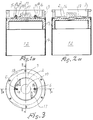
- Figs. 1a, 1b and 2a, 2b show lateral sections through Fig. 3 and an end elevation of a protective canister of the type characteristic of the present invention, more specifically,
- Fig. 1a is a section taken along the line A-A in Fig. 3 with the sub-combat unit in place within the protective canister;
- Fig. 1b shows the same section as Fig. 1a but in the position immediately after the sub-combat unit has been discharged, while
- Fig. 2a shows the section taken along the line B-B in Fig. 3 in the same position as Fig. 1a; and finally
- Fig. 2b shows the same lateral section as Fig. 2a but at the same functional position as Fig. 1b.
- The
protective canister 1 is composed of aninner bottom portion 2, an annularouter bottom portion 3 disposed concentrically around the inner bottom portion, and a tubular protective can 4. The protective can 4 is glued or welded to the outer edge of theouter bottom portion 3, and theinner bottom portion 2 is inserted in the central aperture of the outer bottom portion by means of shear pins or keepers, 5 and 6, respectively. These latter are secured by means of specifically adapted washers and bolts, 8 and 9, respectively. A pyrocharge is disposed in a specifically adaptedcombustion chamber 10 in the inner bottom portion, discharge generating gas 11 on its initiation. In addition to a sub-combat unit marked 12 on the figures, theprotective canister 1 also contains drivingsabot 13 disposed between the bottom of the canister and the sub-combat unit and displaceable interiorly in the canister. The displacement of the drivingsabot 13 in relation to theinner lid portion 2 is determined by twobrake bands inner bottom portion 2 and in the driving sabot. In the initial phase, the brake bands are folded in specifically adapted grooves of which one is marked withreference numeral 16 and is visible in Figs. 2a and 2b. The brake bands are, in the present example, produced from stainless steel of extreme extensibility. The anchorage in the lid portion and driving sabot, respectively, is effected with the aid of through grooves and locking pins. The locking pins for the anchorage in thebottom portion 2 havereference numerals - At the predetermined time for separation, the gas-generating pyrokit 11, which appropriately consists of a powder charge, is initiated. On the deflagration of the powder charge, a pressure is built up in the
combustion chamber 10 and the drivingsabot 13 is given a separation speed which is determined by the size and combustion speed of the separation charge. Once the separation phase has started, the pressure increases in the pressurized volume. The force on the interior end surfaces (the insides of thebottom portions sabot 13 facing towards them) imparts to the driving sabot and thecombustion chamber 10 an increased separation velocity. When the velocity of the separated parts increases and thereby the volume increase between them, the volume increase takes place, however, more rapidly than the separation charge 11 produces hot powder gases and consequently the pressure falls. When the pressure has fallen to approximately atmospheric, thebrake bands keepers 5 and 6, and the drivingsabot 13 with thebottom portion 2 connected via thebrake bands other parts 3 and 4 of the protective canister, whereafter these separated parts follow their own trajectories towards the ground. For instance, theouter lid portion 3 may possibly have rotation brakes and friction brakes still in place, which can impart a stable trajectory to this portion, while the driving sabot with its connected lid portion will assume a tumbling trajectory. The sub-combat unit, which will have already departed from the protective canister before the driving sabot has been wholly arrested and thekeepers 5 and 6 severed, will then have already achieved its own stable and completely different predetermined trajectory and had time to flip out its sensor and aerodynamic surfaces.
Claims (6)
- A method of separating, from a protective canister (1) of the type having a first open end and a second closed end, sub-combat units (12) of the type which has its own triggering sensors and bursting charges and which is transported in said protective canister (1) by a vehicle or carrier body in the form of a shell or missile to a predetermined target area where the protective canister (1) with the enclosed sub-combat unit (12) is removed from the carrier body, whereafter the protective canister (1) and the sub-combat unit (12) after possible retardation in respect of both the direction of travel of the carrier body and possible rotation, are to be separated from each other by an elevated gas pressure generated by the combustion of a gas-generating pyrotechnical charge (11) discharging the sub-combat unit out of the open end of the protective canister characterized in that the sub-combat unit (12) is discharged out of the protective canister (1) by a driving sabot (13) displaceable therein, behind which said elevated gas pressure is generated, said displaceable driving sabot (13) being prevented, by arrest means (14, 15) connecting it with the canister, from accompanying the sub-combat unit (12) in its thus achieved new trajectory.
- The method as claimed in claim 1, characterized in that the retardation of the displaceable driving sabot (13) is arranged to give rise to a division of the protective canister (1) into a plurality of parts (2, 14, 15, 13; and 3, 4, respectively), which ensures that the parts enter into different trajectories and/or assume different fall velocities than the sub-combat unit (12).
- A protective canister of the type having a first open end and a second closed end and containing and,on all sides but one, surrounding a separable sub-combat unit (12) of the type which includes at least one own triggering sensor, a bursting charge and one or more flip-out carrier surfaces imparting to the sub-combat unit (12) in the flipped-out state a predetermined fall trajectory which is to give the triggering sensors the opportunity of scanning a predetermined target area in order, on identifying a target, to combat the same with the bursting charge, said protective canister (1) being transported together with its associated sub-combat unit (12) by a vehicle or carrier body in the form of a shell or missile to the pertinent target area in order there to be separated from the carrier body and said sub-combat unit (12) being separated from the protective canister (1) by an elevated gas pressure generated by the combustion of a gas-generating pyrotechnical charge (11) between the closed end of said canister (1) and the sub-combat unit (12) characterized in that in the protective canister (1) there is disposed, in addition to the sub-combat unit (12) a displaceable driving sabot or ram (13) between the sub-combat unit and the initially enclosed end (2, 3) of the canister, said sabot or ram abutting against the sub-combat unit (12) and in that between said sabot or ram and the bottom (2, 3) of the canister there is disposed said gas-generating pyrotechnical charge (11), said canister also including arrest means (14, 15) which are interconnected between said sabot and said initially closed end of the canister and which retard the displacement of the sabot (13) after a predetermined displacement distance.
- The protective canister (1) as claimed in claim 3, characterized in that the displaceable driving sabot (13) is connected to the bottom (2, 3) of the protective canister (1) by means of 2 or more initially folded brake bands (14, 15) which, in the taut state, arrest the continued displacement of the driving sabot in relation to the bottom (2, 3) of the protective canister.
- The protective canister (1) as claimed in claim 4, characterized in that the part of its bottom (2) in which the brake bands are secured is provided with indications of fracture (5, 6) in relation to the remainder of the protective canister (3, 4) which are adapted so as to break as a result of the jerk which is created when the brake bands (14, 15) are wholly taut and the movement of the driving sabot (13) is arrested, whereby the protective canister (1) with accessories is divided into parts (2, 14, 15, 13; and 3, 4, respectively) which enter into their own fall trajectories.
- The protective canister (1) as claimed in claim 5, characterized in that its bottom consists of two mutually concentrically disposed parts (2, 3), the brake bands being secured in the central portion (2), and there parts (2, 3) being held together by sheer pins or keepers (5, 6) adapted to break when the brake bands (14, 15) are wholly taut.
Applications Claiming Priority (2)
| Application Number | Priority Date | Filing Date | Title |
|---|---|---|---|
| SE9103081A SE9103081L (en) | 1991-10-23 | 1991-10-23 | SAVED FROM A PROTECTOR CAN SEPARATE SUBSTRATE PARTS AND PROTECTOR |
| SE9103081 | 1991-10-23 |
Publications (3)
| Publication Number | Publication Date |
|---|---|
| EP0539340A2 EP0539340A2 (en) | 1993-04-28 |
| EP0539340A3 EP0539340A3 (en) | 1993-12-22 |
| EP0539340B1 true EP0539340B1 (en) | 1996-01-03 |
Family
ID=20384078
Family Applications (1)
| Application Number | Title | Priority Date | Filing Date |
|---|---|---|---|
| EP92850238A Expired - Lifetime EP0539340B1 (en) | 1991-10-23 | 1992-10-09 | Launching system for a submunition |
Country Status (5)
| Country | Link |
|---|---|
| US (1) | US5315933A (en) |
| EP (1) | EP0539340B1 (en) |
| AT (1) | ATE132616T1 (en) |
| DE (1) | DE69207343T2 (en) |
| SE (1) | SE9103081L (en) |
Families Citing this family (4)
| Publication number | Priority date | Publication date | Assignee | Title |
|---|---|---|---|---|
| SE508475C2 (en) * | 1993-03-30 | 1998-10-12 | Bofors Ab | Method and apparatus for spreading combat parts |
| SE501082C2 (en) * | 1993-03-30 | 1994-11-07 | Bofors Ab | Method and apparatus for giving an airborne combat section a desired pattern of movement |
| DE102004061658A1 (en) * | 2004-12-22 | 2006-07-13 | Diehl Bgt Defence Gmbh & Co. Kg | Ejecting acceleration sensitive ammunition from a projectile, comprises accelerating the ammunition during primary and secondary phases |
| SE540780C2 (en) * | 2016-04-06 | 2018-11-06 | Bae Systems Bofors Ab | Divisible grenade with parachute |
Family Cites Families (12)
| Publication number | Priority date | Publication date | Assignee | Title |
|---|---|---|---|---|
| US3677182A (en) * | 1970-10-29 | 1972-07-18 | Us Army | Base ejecting projectile |
| US3712224A (en) * | 1971-06-21 | 1973-01-23 | Us Navy | Decoy flare with traveling ignition charge |
| US4178851A (en) * | 1972-03-08 | 1979-12-18 | The United States Of America As Represented By The Secretary Of The Army | Dual purpose munition |
| SE373939B (en) * | 1973-06-21 | 1975-02-17 | Bofors Ab | |
| DE3111907A1 (en) * | 1981-03-26 | 1982-10-07 | Dynamit Nobel Ag, 5210 Troisdorf | METHOD FOR DISTRIBUTING SUBMUNITION |
| FR2552871B1 (en) * | 1981-04-28 | 1986-11-07 | France Etat Armement | ANTICHAR PROJECTILE ACTING AT SCROLLING SPEED |
| SE452505B (en) * | 1986-03-27 | 1987-11-30 | Bofors Ab | SUBSCRIPTION PART WITH SWINGABLE MOLD DETECTOR |
| DE3823823A1 (en) * | 1988-07-14 | 1990-01-18 | Diehl Gmbh & Co | SKULL HEAD |
| SE464833B (en) * | 1989-10-20 | 1991-06-17 | Bofors Ab | SUBSCRIPTION PART WITH SWINGABLY ORGANIZED MEAL DETECTOR AND BARE AREA |
| DE3937762C2 (en) * | 1989-11-14 | 1993-11-25 | Diehl Gmbh & Co | Artillery shell submunition |
| SE465440B (en) * | 1990-04-04 | 1991-09-09 | Bofors Ab | submunition |
| US5160800A (en) * | 1991-04-24 | 1992-11-03 | The United States Of America As Represented By The Secretary Of The Navy | Obturator retaining means |
-
1991
- 1991-10-23 SE SE9103081A patent/SE9103081L/en not_active IP Right Cessation
-
1992
- 1992-10-09 AT AT92850238T patent/ATE132616T1/en not_active IP Right Cessation
- 1992-10-09 EP EP92850238A patent/EP0539340B1/en not_active Expired - Lifetime
- 1992-10-09 DE DE69207343T patent/DE69207343T2/en not_active Expired - Fee Related
- 1992-10-22 US US07/964,963 patent/US5315933A/en not_active Expired - Fee Related
Also Published As
| Publication number | Publication date |
|---|---|
| SE468568B (en) | 1993-02-08 |
| DE69207343T2 (en) | 1996-08-01 |
| EP0539340A3 (en) | 1993-12-22 |
| EP0539340A2 (en) | 1993-04-28 |
| SE9103081L (en) | 1993-02-08 |
| DE69207343D1 (en) | 1996-02-15 |
| ATE132616T1 (en) | 1996-01-15 |
| US5315933A (en) | 1994-05-31 |
Similar Documents
| Publication | Publication Date | Title |
|---|---|---|
| US8387540B2 (en) | Interceptor projectile and method of use | |
| US4922826A (en) | Active component of submunition, as well as flechette warhead and flechettes therefor | |
| US6957602B1 (en) | Parachute active protection apparatus | |
| US6672220B2 (en) | Apparatus and method for dispersing munitions from a projectile | |
| US5760330A (en) | Method and apparatus for conveying a large-calibre payload over an operational terrain | |
| US4744301A (en) | Safer and simpler cluster bomb | |
| EP2577216B1 (en) | Vehicle stabilization in the event of large detonation | |
| US4622900A (en) | Exploding missile | |
| CA2234726A1 (en) | Ballistically deployed restraining net | |
| US5814753A (en) | Device for the nonlethal combating of aircraft | |
| US3626415A (en) | Radar chaff ejector | |
| US3070018A (en) | Nose cone ejection system | |
| US4178854A (en) | Multiple sequential burst system | |
| JPS6347756Y2 (en) | ||
| EP0694156B1 (en) | A method and an apparatus for spreading warheads | |
| EP0539340B1 (en) | Launching system for a submunition | |
| US7261039B1 (en) | Artillery Rocket Kinetic Energy Rod Warhead | |
| US3290681A (en) | Device for jamming radar detection and interception of ballistic missiles | |
| JP3466615B2 (en) | Method and apparatus for imparting a desired motion pattern to an airborne warhead | |
| US5299503A (en) | Shell whose base serves as the parachute can of a submunition | |
| GB2142418A (en) | Cluster bombs | |
| IL127136A (en) | Projectile having a radial direction of action | |
| RU22326U1 (en) | CARRIER MISSILE DEFENSE DEVICE | |
| NL192694C (en) | Projectile. | |
| US3434417A (en) | Bomb braking system |
Legal Events
| Date | Code | Title | Description |
|---|---|---|---|
| PUAI | Public reference made under article 153(3) epc to a published international application that has entered the european phase |
Free format text: ORIGINAL CODE: 0009012 |
|
| AK | Designated contracting states |
Kind code of ref document: A2 Designated state(s): AT BE CH DE DK ES FR GB GR IT LI NL SE |
|
| PUAL | Search report despatched |
Free format text: ORIGINAL CODE: 0009013 |
|
| AK | Designated contracting states |
Kind code of ref document: A3 Designated state(s): AT BE CH DE DK ES FR GB GR IT LI NL SE |
|
| 17P | Request for examination filed |
Effective date: 19940517 |
|
| 17Q | First examination report despatched |
Effective date: 19940919 |
|
| GRAA | (expected) grant |
Free format text: ORIGINAL CODE: 0009210 |
|
| AK | Designated contracting states |
Kind code of ref document: B1 Designated state(s): AT BE CH DE DK ES FR GB GR IT LI NL SE |
|
| PG25 | Lapsed in a contracting state [announced via postgrant information from national office to epo] |
Ref country code: NL Free format text: LAPSE BECAUSE OF FAILURE TO SUBMIT A TRANSLATION OF THE DESCRIPTION OR TO PAY THE FEE WITHIN THE PRESCRIBED TIME-LIMIT Effective date: 19960103 Ref country code: GR Free format text: LAPSE BECAUSE OF FAILURE TO SUBMIT A TRANSLATION OF THE DESCRIPTION OR TO PAY THE FEE WITHIN THE PRESCRIBED TIME-LIMIT Effective date: 19960103 Ref country code: ES Free format text: THE PATENT HAS BEEN ANNULLED BY A DECISION OF A NATIONAL AUTHORITY Effective date: 19960103 Ref country code: DK Effective date: 19960103 Ref country code: BE Effective date: 19960103 Ref country code: AT Effective date: 19960103 |
|
| REF | Corresponds to: |
Ref document number: 132616 Country of ref document: AT Date of ref document: 19960115 Kind code of ref document: T |
|
| ITF | It: translation for a ep patent filed |
Owner name: BARZANO' E ZANARDO ROMA S.P.A. |
|
| ET | Fr: translation filed | ||
| REF | Corresponds to: |
Ref document number: 69207343 Country of ref document: DE Date of ref document: 19960215 |
|
| REG | Reference to a national code |
Ref country code: CH Ref legal event code: NV Representative=s name: E. BLUM & CO. PATENTANWAELTE |
|
| PG25 | Lapsed in a contracting state [announced via postgrant information from national office to epo] |
Ref country code: SE Effective date: 19960403 |
|
| NLV1 | Nl: lapsed or annulled due to failure to fulfill the requirements of art. 29p and 29m of the patents act | ||
| PLBE | No opposition filed within time limit |
Free format text: ORIGINAL CODE: 0009261 |
|
| STAA | Information on the status of an ep patent application or granted ep patent |
Free format text: STATUS: NO OPPOSITION FILED WITHIN TIME LIMIT |
|
| 26N | No opposition filed | ||
| PGFP | Annual fee paid to national office [announced via postgrant information from national office to epo] |
Ref country code: FR Payment date: 19980911 Year of fee payment: 7 |
|
| PGFP | Annual fee paid to national office [announced via postgrant information from national office to epo] |
Ref country code: CH Payment date: 19980918 Year of fee payment: 7 |
|
| PGFP | Annual fee paid to national office [announced via postgrant information from national office to epo] |
Ref country code: GB Payment date: 19981009 Year of fee payment: 7 |
|
| PGFP | Annual fee paid to national office [announced via postgrant information from national office to epo] |
Ref country code: DE Payment date: 19981221 Year of fee payment: 7 |
|
| PG25 | Lapsed in a contracting state [announced via postgrant information from national office to epo] |
Ref country code: GB Free format text: LAPSE BECAUSE OF NON-PAYMENT OF DUE FEES Effective date: 19991009 |
|
| PG25 | Lapsed in a contracting state [announced via postgrant information from national office to epo] |
Ref country code: LI Free format text: LAPSE BECAUSE OF NON-PAYMENT OF DUE FEES Effective date: 19991031 Ref country code: CH Free format text: LAPSE BECAUSE OF NON-PAYMENT OF DUE FEES Effective date: 19991031 |
|
| GBPC | Gb: european patent ceased through non-payment of renewal fee |
Effective date: 19991009 |
|
| REG | Reference to a national code |
Ref country code: CH Ref legal event code: PL |
|
| PG25 | Lapsed in a contracting state [announced via postgrant information from national office to epo] |
Ref country code: FR Free format text: LAPSE BECAUSE OF NON-PAYMENT OF DUE FEES Effective date: 20000630 |
|
| PG25 | Lapsed in a contracting state [announced via postgrant information from national office to epo] |
Ref country code: DE Free format text: LAPSE BECAUSE OF NON-PAYMENT OF DUE FEES Effective date: 20000801 |
|
| REG | Reference to a national code |
Ref country code: FR Ref legal event code: ST |
|
| PG25 | Lapsed in a contracting state [announced via postgrant information from national office to epo] |
Ref country code: IT Free format text: LAPSE BECAUSE OF NON-PAYMENT OF DUE FEES;WARNING: LAPSES OF ITALIAN PATENTS WITH EFFECTIVE DATE BEFORE 2007 MAY HAVE OCCURRED AT ANY TIME BEFORE 2007. THE CORRECT EFFECTIVE DATE MAY BE DIFFERENT FROM THE ONE RECORDED. Effective date: 20051009 |