EP0539074B1 - Multi-component applicator assembly - Google Patents
Multi-component applicator assembly Download PDFInfo
- Publication number
- EP0539074B1 EP0539074B1 EP92309270A EP92309270A EP0539074B1 EP 0539074 B1 EP0539074 B1 EP 0539074B1 EP 92309270 A EP92309270 A EP 92309270A EP 92309270 A EP92309270 A EP 92309270A EP 0539074 B1 EP0539074 B1 EP 0539074B1
- Authority
- EP
- European Patent Office
- Prior art keywords
- assembly
- barrel
- barrels
- removable
- applicator
- Prior art date
- Legal status (The legal status is an assumption and is not a legal conclusion. Google has not performed a legal analysis and makes no representation as to the accuracy of the status listed.)
- Expired - Lifetime
Links
Images


Classifications
-
- B—PERFORMING OPERATIONS; TRANSPORTING
- B05—SPRAYING OR ATOMISING IN GENERAL; APPLYING FLUENT MATERIALS TO SURFACES, IN GENERAL
- B05C—APPARATUS FOR APPLYING FLUENT MATERIALS TO SURFACES, IN GENERAL
- B05C5/00—Apparatus in which liquid or other fluent material is projected, poured or allowed to flow on to the surface of the work
-
- B—PERFORMING OPERATIONS; TRANSPORTING
- B05—SPRAYING OR ATOMISING IN GENERAL; APPLYING FLUENT MATERIALS TO SURFACES, IN GENERAL
- B05C—APPARATUS FOR APPLYING FLUENT MATERIALS TO SURFACES, IN GENERAL
- B05C17/00—Hand tools or apparatus using hand held tools, for applying liquids or other fluent materials to, for spreading applied liquids or other fluent materials on, or for partially removing applied liquids or other fluent materials from, surfaces
- B05C17/005—Hand tools or apparatus using hand held tools, for applying liquids or other fluent materials to, for spreading applied liquids or other fluent materials on, or for partially removing applied liquids or other fluent materials from, surfaces for discharging material from a reservoir or container located in or on the hand tool through an outlet orifice by pressure without using surface contacting members like pads or brushes
- B05C17/00503—Details of the outlet element
- B05C17/00506—Means for connecting the outlet element to, or for disconnecting it from, the hand tool or its container
-
- B—PERFORMING OPERATIONS; TRANSPORTING
- B05—SPRAYING OR ATOMISING IN GENERAL; APPLYING FLUENT MATERIALS TO SURFACES, IN GENERAL
- B05C—APPARATUS FOR APPLYING FLUENT MATERIALS TO SURFACES, IN GENERAL
- B05C17/00—Hand tools or apparatus using hand held tools, for applying liquids or other fluent materials to, for spreading applied liquids or other fluent materials on, or for partially removing applied liquids or other fluent materials from, surfaces
- B05C17/005—Hand tools or apparatus using hand held tools, for applying liquids or other fluent materials to, for spreading applied liquids or other fluent materials on, or for partially removing applied liquids or other fluent materials from, surfaces for discharging material from a reservoir or container located in or on the hand tool through an outlet orifice by pressure without using surface contacting members like pads or brushes
- B05C17/00503—Details of the outlet element
- B05C17/00516—Shape or geometry of the outlet orifice or the outlet element
-
- B—PERFORMING OPERATIONS; TRANSPORTING
- B05—SPRAYING OR ATOMISING IN GENERAL; APPLYING FLUENT MATERIALS TO SURFACES, IN GENERAL
- B05C—APPARATUS FOR APPLYING FLUENT MATERIALS TO SURFACES, IN GENERAL
- B05C17/00—Hand tools or apparatus using hand held tools, for applying liquids or other fluent materials to, for spreading applied liquids or other fluent materials on, or for partially removing applied liquids or other fluent materials from, surfaces
- B05C17/005—Hand tools or apparatus using hand held tools, for applying liquids or other fluent materials to, for spreading applied liquids or other fluent materials on, or for partially removing applied liquids or other fluent materials from, surfaces for discharging material from a reservoir or container located in or on the hand tool through an outlet orifice by pressure without using surface contacting members like pads or brushes
- B05C17/00553—Hand tools or apparatus using hand held tools, for applying liquids or other fluent materials to, for spreading applied liquids or other fluent materials on, or for partially removing applied liquids or other fluent materials from, surfaces for discharging material from a reservoir or container located in or on the hand tool through an outlet orifice by pressure without using surface contacting members like pads or brushes with means allowing the stock of material to consist of at least two different components
-
- B—PERFORMING OPERATIONS; TRANSPORTING
- B05—SPRAYING OR ATOMISING IN GENERAL; APPLYING FLUENT MATERIALS TO SURFACES, IN GENERAL
- B05C—APPARATUS FOR APPLYING FLUENT MATERIALS TO SURFACES, IN GENERAL
- B05C17/00—Hand tools or apparatus using hand held tools, for applying liquids or other fluent materials to, for spreading applied liquids or other fluent materials on, or for partially removing applied liquids or other fluent materials from, surfaces
- B05C17/005—Hand tools or apparatus using hand held tools, for applying liquids or other fluent materials to, for spreading applied liquids or other fluent materials on, or for partially removing applied liquids or other fluent materials from, surfaces for discharging material from a reservoir or container located in or on the hand tool through an outlet orifice by pressure without using surface contacting members like pads or brushes
- B05C17/01—Hand tools or apparatus using hand held tools, for applying liquids or other fluent materials to, for spreading applied liquids or other fluent materials on, or for partially removing applied liquids or other fluent materials from, surfaces for discharging material from a reservoir or container located in or on the hand tool through an outlet orifice by pressure without using surface contacting members like pads or brushes with manually mechanically or electrically actuated piston or the like
-
- B—PERFORMING OPERATIONS; TRANSPORTING
- B65—CONVEYING; PACKING; STORING; HANDLING THIN OR FILAMENTARY MATERIAL
- B65D—CONTAINERS FOR STORAGE OR TRANSPORT OF ARTICLES OR MATERIALS, e.g. BAGS, BARRELS, BOTTLES, BOXES, CANS, CARTONS, CRATES, DRUMS, JARS, TANKS, HOPPERS, FORWARDING CONTAINERS; ACCESSORIES, CLOSURES, OR FITTINGS THEREFOR; PACKAGING ELEMENTS; PACKAGES
- B65D81/00—Containers, packaging elements, or packages, for contents presenting particular transport or storage problems, or adapted to be used for non-packaging purposes after removal of contents
- B65D81/32—Containers, packaging elements, or packages, for contents presenting particular transport or storage problems, or adapted to be used for non-packaging purposes after removal of contents for packaging two or more different materials which must be maintained separate prior to use in admixture
- B65D81/325—Containers having parallel or coaxial compartments, provided with a piston or a movable bottom for discharging contents
Definitions
- the present invention relates to a multiple component applicator assembly which dispenses plural component materials together in a mixed state from separate component material sources. More particularly, the present invention relates to such a multiple component applicator assembly which is convertible between plural component number assemblies.
- component materials are stored separate from one another and are dispensed concurrently with one another such that the correct ratio of component materials for a proper mixture are provided.
- the component materials may be mixed within such applicator devices, or may be mixed externally after the proper proportional amounts are dispensed.
- adhesives may comprise multiple components.
- Such adhesives may include components including epoxies, urethanes, acrylics, polysulfides, polyesters, silicones, and any other known or discovered adhesive or sealant materials.
- Epoxy adhesives are representative of such multiple component adhesives, and more generally of multiple component products, which require that the component materials be stored individually and which must be mixed in accordance with a specific ratio for usage.
- Epoxy adhesives typically include an epoxy resin component and a curing agent component such that when mixed together in proper proportion, the epoxy curative hardens in place.
- epoxy adhesive dispensing devices have been developed which include separate storage locations for the resin component and the curing agent component and a means for dispensing the separate components together and in accordance with the proper ratio for curing.
- One manner of concurrently dispensing separate component materials is to provide the component materials within distinct cavities or barrels of an applicator device and to force the component materials from such cavities or barrels by actuation of a single element.
- dispensers including plural barrels which each contain a component material which is expelled by a plunger inserted within each barrel, and wherein the plungers are driven together by the manipulation of a single element are disclosed in U. S. Patent Nos. 4,471,888 to Herb et al, 3,952,920 to Bergman, and 2,826,339 to Maillard, and in German Offenlegungsschrift 2,335,601.
- a somewhat more versatile dispenser is described in U.S. Patent No. 3,828,980 to Creighton et al, in that the device includes a like number of pistons as there are component material holding barrels, wherein the pistons are separable from one another but are actuatable together by a separable rigid connecting means.
- the Creighton et al device is disadvantageous for the same reason as the above-described devices in that the multiple component barrels are formed as a single cartridge which is divided into compartments which are non-divisible from one another.
- the dispenser whether having two or more component barrels, is limited in use to producing a mixture of that number of components as there are fixed barrels and at the predetermined ratio thereof.
- Schroeder U.S. Patent No. 4,260,077 discloses yet a more versatile dispenser, wherein the dispenser comprises not only separable plungers, but also separable barrels.
- the barrels are detachably connected together by a sliding interlock, and the plungers are moved concurrently by inter-fitted elements.
- the principle advantage of the Schroeder device is that each one of the barrel and plunger assemblies is usable independently of the other.
- the dispenser is particularly directed to a dispenser which can equally dispense component material from two barrels and can be separated for individual use of each barrel and plunger assembly. Because of the need for each separable barrel and plunger assembly to be independently usable, each assembly necessarily includes all of the necessary operable component parts, including nozzles. Thus, even when connected together and dispensing two component materials together, the component materials are expelled through individual discharge openings, and the component materials must then be mixed together externally of the dispenser by other means.
- a significantly advanced two component applicator assembly has been developed with increased two component versatility and is available as the "Scotch-WeldTM EPX Applicator System” from Minnesota Mining and Manufacturing Company of St. Paul, Minnesota, the assignee of the present invention.
- the "Scotch-WeldTM EPX Applicator System” comprises an applicator and plunger assembly to which a removable fixed two component barrel assembly is detachably connected.
- the barrel assembly further includes a separable static mixing nozzle connecting to the discharge openings of both components.
- Many varieties of two component room temperature curing products are available prepackaged within the removable barrel assemblies from Minnesota Mining and Manufacturing Company under the product line " Scotch-Weld Duo-Pak" adhesive cartridges.
- a user of the applicator can purchase any one of the available adhesives and simply attach the barrel assembly to the applicator and plunger assembly for dispensing.
- the individual prepackaged barrel assemblies for specific adhesives are designed in accordance with a predetermined mix ratio for that specific adhesive.
- a single applicator and plunger assembly can dispense any one of the variety of available two component adhesives at the predetermined ratio depending on the specific adhesive and use thereof.
- RATIO-PAKTM Cartridge System from Plus-Pak Industries, Inc., of Niantic, CT.
- This system includes a removable cartridge system, like the “Scotch-Weld”TM System, where the cartridge system consists of two separable cartridges (barrels). Different cartridge sizes are available so that they can be configured to dispense components at selected mix ratios, specifically within the range of 1:1 to 10:1.
- the "Scotch-WeldTM EPX Applicator System" and all other two component applicator devices suffer from a common problem which occurs when a third component, or more, is attempted to be added to the two components which is not compatible or stable with the other two components. Moreover, even if a third component is compatible or stable with at least one of the other two components, such two component devices lack the versatility to be able to selectively add such a third component to the other two components only when desired. For example, one may wish to add a third component during only a portion of the application of a two component adhesive.
- components not compatible or stable would include materials which react with the base material or anything of higher density than the base material, such as flame retardants, glass beads, conductive metal, thermally conductive fillers, and the like, where such higher density materials would tend to settle within the tubes during storage before use. In the same manner, lower density additives would tend to float within the base material destroying a uniform mixture.
- Applicator devices including the capability of dispensing three or more components are also known.
- the aforementioned U.S. Patent No. 2,826,339 to Maillard discloses in one embodiment a three component dispenser having three coaxial compartments from which the components are concurrently dispensed.
- Such a device is no more versatile than a fixed two component device in that it is limited in use to component materials of a like number as there are fixed compartments.
- Falco U.S. Patent No. 4,913,553, which represents the prior art as referred to in the preamble of claim 1, discloses a multi-component dispensing apparatus having more than two component barrels, but which is limited to the provision of a pair of dispensing barrels for each component material to be dispensed.
- the device in accordance with that invention, must have an even number of component barrels which are equally distributed about the drive axis of the device for balancing the device during application. It is suggested that more than two component materials can be dispensed if the additional components are provided by a pair of additional component barrels balanced about the drive axis.
- This device like those described above, is limited in use for applying and dispensing component materials of a specific number for which the applicator apparatus is specifically designed.
- DE-A-2 335 601 describes an applicator with a fixed and a removable barrel which may be used to dispense flowable materials.
- the removable barrel is mounted at 90° to the fixed barrel.
- Both fixed and removable barrels have ratchet advancing devices for the plungers in the barrels, the two ratchet systems being connected together by a linkage which includes a dead space.
- the present invention is directed to an applicator assembly for concurrently dispensing plural flowable component materials, which overcomes the aforementioned shortcomings associated with prior art multiple component dispensers. Specifically, the present invention has an increased versatility and is usable in situations where one or more additional components can be concurrently dispensed with basic two component materials. Furthermore, the present invention is particularly applicable to the dispensing of one or more additional components or additives concurrently with two part adhesives, sealants, coatings, and potting compounds, such as epoxies, urethanes, acrylics, polysulfides, polyester, silicones, and the like. It is understood that any other such components are contemplated.
- the present invention is beneficial in that it allows a user to apply three or more part chemical systems; for example, a third catalyst component or additive that may not be compatible and/or stable (reactable) with the other two components.
- a third catalyst component or additive that may not be compatible and/or stable (reactable) with the other two components.
- Such an applicator assembly can advantageously utilize such a catalyst or an inhibitor to custom tailor the cure speed of adhesives, such as epoxies.
- the applicator assembly of the present invention permits the utilization of three or more part chemistries.
- the applicator assembly of the present invention accommodates the application of one or more additives with a conventional two part component material.
- a colour component material can be mixed with and dispensed with a conventional two part white or colourless adhesive to proved the ultimate colour of the applied adhesive.
- a user could simply stock such a white or colourless adhesive and a variety of colour components which could be selectively added for each particular situation.
- additives could be mixed and dispensed with a conventional two part adhesive: flame retardants, conductive fillers, other fillers, or the like.
- Such additives may be unstable and/or non-compatible with the components of the two part material such that mixture within one or both of the component materials would not be possible.
- the present invention allows such additives to be consistently and evenly mixed with the two component materials at the time of dispensing at application thereof to a substrate. Thus, the adverse affects are avoided.
- Non-stable additives include those that would physically settle out of the component materials during storage before use, as may occur when the additive has a higher or lower density than the component materials.
- an applicator assembly for concurrently dispensing a plurality of flowable component materials, comprising: a plurality of barrels fixed with one another, at least two of the barrels for containing a flowable component material and having a discharge port through which the flowable component material is to be concurrently dispensed from said applicator assembly; characterized by a removable barrel assembly releasably attached to said plurality of fixed barrels by way of a cooperating releasable attachment means, said removable barrel assembly including at least one removable barrel for containing a flowable component material and having a discharge port through which the flowable component material is to be dispensed with the other component materials; and means for concurrently dispensing the flowable component materials from said discharge ports of said at least two barrels of said plurality of fixed barrels and said discharge port of said at least one removable barrel of said removable barrel assembly, said means for concurrently dispensing the flowable component materials comprising; a plunger assembly including a plunger
- an applicator assembly in the form of a kit of parts, said applicator assembly being convertible between plural different component number multi-component arrangements for concurrently dispensing a plurality of flowable component materials in each arrangement, comprising: a barrel assembly including at least two barrels fixed with one another, each barrel containing a flowable component material and having a discharge port through which the flowable component material is to be concurrently dispensed from said applicator assembly; a removable barrel for containing a flowable component material and having a discharge port through which the flowable component material is to be dispensed, said removable barrel being detachably connectable with the other barrels of said barrel assembly; means for concurrently dispensing the plurality of flowable component materials from said discharge ports of said barrels for each arrangement; and nozzle means for receiving the component materials from said discharge ports of said barrels, for mixing said component materials and dispensing said component materials from a single discharge outlet, wherein, in a first arrangement with said removable barrel connected with said barrel assembly, said
- a supplemental component assembly for converting an applicator device, which is used for concurrently dispensing a plurality of flowable component materials, into an increased component number applicator assembly
- said supplemental component assembly comprising a detachable barrel assembly including at least one removable barrel having a discharge port at one end thereof, said detachable barrel assembly including means for detachably connecting said removable barrel to a barrel assembly of the applicator, said barrel assembly including a plurality of barrels fixed with one another; a nozzle adapter means which connects with said discharge port of said removable barrel and is further connectable with discharge ports of each fixed barrel of the applicator device, said nozzle adapter means having passages for providing flow paths from each of the discharge ports to a common passage within said nozzle adapter means within which the component materials are mixed with one another and which leads to a single adapter outlet; means for dispensing a component material from within said removable barrel that is operatively connectable with a means for concurrently dispensing a plurality
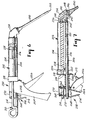
- the multi-component applicator assembly 10 includes a barrel assembly 12 having a plurality of barrels 14 fixed with respect to one another and at least one detachable barrel 16.
- the barrel assembly 12 is also preferably easily separable from the remainder of the applicator assembly 10, the remainder comprising a means for concurrently dispensing flowable component materials 18.
- the means for concurrently dispensing flowable component materials 18 comprises a plunger assembly 20 and an advancing means 22.
- the plunger assembly 20 comprises a fixed plunger 24 for each fixed barrel 14.
- the fixed plungers 24 are substantially independent from one another along their longitudinal length from the ends 26 thereof which are inserted within the fixed barrels 14 so as not to obstruct longitudinal movement of such ends 26 along the longitudinal length of and within the fixed barrels 14.
- a web portion 28 is provided at the ends of fixed plungers 24 distal from the inserted ends 26.
- the fixed plungers 24 are operatively connected to move with one another at all times.
- the plunger assembly 20 further includes an auxiliary plunger 30 which is operatively attached with the fixed plungers 24, preferably at the web portion 28 thereof.
- the auxiliary plunger 30 is given a length that operatively corresponds to the length of each fixed plunger 24 such that an end 32 thereof is inserted within detachable barrel 16 to substantially the same degree that the ends 26 of fixed plungers 24 are inserted within fixed barrels 14. That is, the end surfaces of end 32 and ends 26 of the auxiliary plunger 30 and fixed plungers 24, respectively, lie substantially within the same transverse plane.
- the advancing means 22, described below concurrently moves fixed plungers 24 and auxiliary plunger 30 together such that the ends 32 and 26 thereof move together. That is, at the same time and over the same displacement.
- Auxiliary plunger 30 is operatively connected with the web portion 28 by any conventional technique.
- the auxiliary plunger 30 is detachably connected to the web portion 28.
- alternate techniques are illustrated to provide such a detachable connection, although other techniques are contemplated.
- the web portion 28 is provided with an opening 34 within which a hub portion 36 of the auxiliary plunger 30 is inserted.
- the opening 34 in the preferred embodiment is circular; however, other shaped openings are contemplated and can be advantageously used.
- the auxiliary plunger 30 further includes a stem portion 38 which is connected with the hub portion 36 by any conventional means, such as screws 39 as shown in Figure 1.
- the stem portion 38 could alternatively be snap fitted or plugged into the side of hub portion 36.
- the hub portion 36 is similarly shaped at its lower portion to the shape of the opening 34 and includes a perimetric flange 40 which sets on an upper surface of the web portion 28.
- tabs 42 are resiliently connected with the hub portion 36 so that they can be sprung inwardly to pass through the opening 34 but are biased to a locked position as shown in Figure 5A.
- the tabs 42 are conventionally provided such as by slots 44 shown in Figure 1.
- the hub portion 36′ is similarly provided with a perimetric flange 40′ which sets on the upper surface of the web portion 28.
- the lower end of the hub portion 36′ extends within the opening 34.
- the perimetric flange 40′ is detachably connected with web portion 28 by screws 46 which pass through bores provided within the web portion 28 and are threaded into the perimetric flange 40′. It is understood that many other types of detachable connections could be substituted for those illustrated in Figures 5A and 5B, where the purpose is such that the auxiliary plunger 30 can be detachably connected with fixed plungers 24 but which when connected are operatively fixed such that all of the plungers move concurrently and equally.
- housing 48 comprises, in fixed relation to one another, a top element 50, a bottom element 52, a reinforcing element 54, and a handle element 56.
- the top element 50 includes an inset portion 58 having a lower guide surface 59 which rides against an upper surface of fixed plungers 24.
- Additional guide surfaces are also preferably provided extending inwardly from the upper edges of both sides of the bottom element 52 so as to ride against lower surfaces of the fixed plungers 24.
- Each of the aforementioned housing elements are fixedly connected with one another by conventional means, which in the case of metal components may be by spot welding or mechanically fastening with rivets, bolts, clips, or the like, or with plastic components by adhesives, heat sealing, mechanical fastening, or the like.
- a trigger 60 is pivotally mounted to the handle element 56 at pivot pin 62.
- the trigger 60 is biased to a forwardmost position by a torsion spring 64 which urges a stop element 66 against the bottom element 52.
- Pivotably mounted atop the trigger 60 is a drive pawl 68 which is spring biased (not shown) in a clockwise direction as shown in Figure 2 by a conventional torsion spring.
- the drive pawl 68 includes a tooth 70 which engages with ratchet teeth 72 extending downwardly from a relatively horizontal lower surface of one or both (preferably both) of the fixed plungers 24. Moreover, the bias of the drive pawl 68 urges tooth 70 thereof into engagement with the ratchet teeth 72, such that during forward movement of the drive pawl 68 by manipulation of trigger 60, the drive pawl 68 urges the fixed plungers 24 and thus auxiliary plunger 30 forwardly. In accordance with known rachet and pawl mechanisms, during the movement of trigger 60 back to its forwardmost position under the influence of torsion spring 64, the drive pawl 68 rides over the ratchet teeth 72 without moving the fixed plungers 24.
- an anti-reverse pawl 74 is preferably pivotally mounted about the pivot pin 62, and is likewise spring biased (not shown) in a clockwise manner by a conventional spring arrangement which effectively urges the anti-reverse pawl 74 so as to engage with a second set of ratchet teeth 76 of fixed plungers 24. It is not necessary that the ratchet teeth 76 be provided, since frictional engagement of the anti-reverse pawl 74 with the fixed plungers 24 would suffice. It is also understood that many other techniques could be used for the described purpose.
- the anti-reverse pawl 74 does not move longitudinally during manipulation of the trigger 60, and the tip 78 thereof remains in engagement with one of the second set of ratchet teeth 76 after forward movement of the fixed plungers 24 to prevent reverse movement. During the forward movement, the tip 78 rides over ratchet teeth 76.
- ratchet teeth 76 are provided at the bottom edge of both fixed plungers 24, and an anti-reverse pawl 74 is provided at both sides of handle element 56.
- both anti-reverse pawls 74 are preferably connected together by a transverse link 80 so that they act in concert with one another.
- a release lever 82 is provided which is a traverse extension of one of the anti-reverse pawls 74.
- an abutment surface 84 which contacts an arm 86 of the drive pawl 68 so as to urge drive pawl 68 away from ratchet teeth 72 at the same time that anti-reverse pawls 74 are released from the second set of ratchet teeth 76 upon depression of the release lever 82.
- the plunger assembly 20 is free to move relative to housing 48.
- housing 48 at bottom element 52, includes side flanges 88, a bottom flange 90, and upper edges 92 of top element 50, which together define a receiving space for a mounting portion 94 of the barrel assembly 12.
- the mounting portion 94 is preferably integrally made with the fixed barrels 14, and preferably, the fixed barrels 14 and mounting portion 94 are molded as a single unit.
- the mounting portion 94 further preferably includes alignment ribs 96 to facilitate the proper alignment of the fixed barrels 14 to the housing 48.
- a barrel assembly 12 can be easily connected to the housing 48 by simply dropping the mounting portion 94 from above within the receiving space defined by side flanges 88, bottom flange 90, and upper edges 92 of housing 48 when the plunger assembly 20 is sufficiently retracted so as not to interfere with such insertion.
- advancement of the plunger assembly 20 prevents the barrel assembly 12 from being removable from housing 48 until the plunger assembly 20 is once again retracted using release lever 82 as described above.
- the detachable barrel 16 is releasably connected with the fixed barrels 14 at the mounting portion 94 thereof by way of a pair of spaced alignment flanges 98 in between which a top edge 100 of the mounting portion 94 is snugly inserted.
- the alignment flanges 98 are illustrated surrounding the detachable barrel 16, it is only necessary that they extend from the bottom side of detachable barrel 16 in order to engage the mounting portion 94.
- the forwardmost spaced alignment flange 98 is further provided with an angled tip 102 which fits between the fixed barrels 14 to transversely locate the detachable barrel 16 relative thereto in proper position.
- a conventional locking feature could be provided between one of or both of alignment flanges 98 and the mounting portion 94.
- a detent (not shown) could be provided on one face of the mounting portion 94 which snap fits within a recess (not shown) provided on the face of one of the alignment flanges 98.
- a nozzle adaptor 104 is provided at the discharge ends of fixed barrels 14 and detachable barrel 16.
- detachable barrel 16 has a reduced diameter nozzle 106 and a discharge port 108.
- the nozzle 106 is preferably slightly tapered for insertion within a similarly tapered cavity 110 of nozzle adaptor 104. The taper fit is preferable in order to make a substantially fluid tight connection of the nozzle adaptor 104 to the barrel assembly 12.
- a releasable connecting means 112 is provided therebetween.
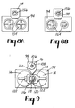
- the releasable connecting means 112 includes, as shown in Figure 9, a substantially flat mounting surface 114 which surrounds a common nozzle 116 for both fixed barrels 14.
- the common nozzle 116 includes an internal wall 118 which bisects the opening of common nozzle 116 into two discharge ports 120, each discharge port 120 being associated with one of the interiors of fixed barrels 14. Thus, component materials can be dispensed from separate discharge ports 120 but through a single common nozzle 116.
- lock elements 122 are provided with portions thereof spaced from and partially overlapping the flat mounting surface 114.
- the lock elements 122 are preferably integrally formed with the fixed barrels 14 and the flat mounting surface 114 such as by a molding process.
- the nozzle adaptor 104 includes a corresponding substantially flat mounting surface 124 which abuts the flat mounting surface 114 of the barrel assembly 12. Additionally, a cavity 126 is provided for accommodating the common nozzle 116. On the external surface of the nozzle adaptor 104, opposite to the flat mounting surface thereof, a plurality of cam surfaces 128 are provided of a like number as there are lock elements 122 of barrel assembly 12. The cam surfaces 128 engage with the inner overlapping surfaces of the lock elements 122 so as to lock the nozzle adaptor 104 to the fixed barrels 14 and to hold flat mounting surfaces 114 and 124 to a substantially fluid tight seal.
- the mounting surface 124 is applied against the mounting surface 114, but with the nozzle adaptor 104 out of rotation by 90 degrees. Then, during rotation of the nozzle adaptor 104 to its normal position illustrated in Figure 1, the cam surfaces 128 act against the lock elements 122 and the nozzle adaptor 104 is locked against the fixed barrels 14.
- a stop surface (not shown) is also preferably provided at the ends of cam surfaces 128 to limit the rotation of the nozzle adaptor 104.
- the nozzle end 106 of the detachable barrel 16 is inserted within the cavity 110 of the nozzle adaptor 104 and the detachable barrel 16 is further connected to the mounting portion 94 at top edge 100 thereof between spaced alignment flanges 98.
- a first passage 130 is provided extending from the cavity 110.
- a second passage 132 is provided from cavity 126, and both passages 130 and 132 intersect with one another at a common passage 134 which leads from that intersection to a single adaptor outlet 136.
- the nozzle adaptor 104 is further provided with a releasable connecting means 138 surrounding the adaptor outlet 136 and including lock elements 140, preferably molded with the nozzle adaptor 104, which are similar to the lock elements 122 of the first releasable connecting means 112. Moreover, the releasable connecting means 138 connects the nozzle adaptor 104 with a nozzle extension 142. In the same manner as the above-described releasable connecting means 112, the releasable connecting means 138 further comprises a flat mounting surface on the nozzle adaptor 104 which surrounds the adaptor outlet 136 and a corresponding flat mounting surface 146 on the nozzle extension 142.
- the nozzle extension 142 includes cam surfaces 148 which interact with the lock elements 140 during a 90 degree rotation of the nozzle extension 142 to lock the nozzle extension 142 with the nozzle adaptor 104.
- the nozzle extension 142 is released by rotating the nozzle extension 142 in a reverse direction of the locking direction by 90 degrees. It is important, but not essential, that connecting means 112 and 138 be similar so that the applicator assembly 10 is useable as a two component device or with additional components, as further emphasized below.
- a static mixing element 150 is provided within the nozzle extension 142.
- the manner of implementing the static mixing element 150 within the nozzle extension 142 is shown and described in U.S. Patent Nos. 3,286,992 and 3,664,638, the disclosures of which are fully incorporated herein by reference.
- the static mixing element 150 consists of a multiple number of serially arranged blades twisted with respect to one another.
- the static mixing element 150 completely mixes the multiple component materials as they move through the nozzle extension 142. This system avoids the introduction of air during the mixing, which results in a better mixing of the component materials, and provides a dispensed line of mixed material which is dense and substantially void free.
- the mixed material is finally dispensed from an applicator assembly dispensing outlet 152 at the tip of the nozzle extension 142.
- the multi-component applicator assembly 10 is a more versatile assembly than the currently available "Scotch-WeldTM EPX Applicator System” which dispenses two mixed components, and is available from Minnesota Mining and Manufacturing Company of St. Paul, Minnesota, the assignee of the present invention.
- Scotch-WeldTM EPX Applicator System two component barrel assemblies are available from Minnesota Mining and Manufacturing Company under the line of adhesive products known as "Duo-Pak” adhesives.
- Duo-Pak adhesives.
- a wide variety of adhesives are available, and the barrel diameters for specific components are designed depending on the component materials and the desired mixing ratio of the two component materials.
- each barrel includes its own slidable piston 154 and 156, respectively, which is driven by the fixed plungers 24 and auxiliary plunger 30, respectively.
- the plungers 24 and 30 could be provided in a sealed relationship with the internal walls of the barrels such that pistons 154 and 156 are unnecessary.
- a supplemental component assembly is provided which is capable of converting the above-described two component "Scotch-WeldTM EPX Applicator System” to a three or more component applicator assembly.
- two component "Scotch-WeldTM EPX Applicators” can be retrofitted to be useable for dispensing three or more components.
- Such a retrofit would include the auxiliary plunger 30, which is connectable to the web portion 28 of fixed plungers 24 as shown in Figures 5A and 5B; the detachable barrel 16, which is connectable to the mounting portion 94 of the fixed barrels 14; and a nozzle adaptor 104 which is insertable between the fixed barrels 14 and the nozzle extension 142 and which is further connected to the detachable barrel 16.
- a multiple component detachable barrel assembly 158 could be just as easily provided as the single detachable barrel 16.
- two detachable barrels 160 are illustrated with the understanding that more detachable barrels could be provided if desired.
- Such a multiple component detachable barrel assembly 158 further necessitates a modified nozzle adaptor 162 with a corresponding number of passages as there are detachable barrels 160 that lead to a common discharge passage.
- the detachable barrels 160 may be separately provided, that is free of connection to one another by being independently mounted on the mounting portion 94 of the fixed barrels 14 in the same manner as the above-described detachable barrel 16.
- the detachable barrels 160 could be provided as a single unit fixed with one another.
- the plunger assembly 20 include a like number of auxiliary plungers 164 as there are detachable barrels 160, with each auxiliary plunger fixed with a hub portion 36 and thus the web portion 28 of the fixed plungers 24 in the same manner as illustrated in Figures 5A and 5B.
- applicator assembly 200 comprises a barrel assembly 202 including a plurality of fixed barrels 204 (only one of which is shown) and a detachable barrel 206, and a means for concurrently dispensing flowable component materials 208 which is made up of a plunger assembly 210 and an advancing means 212.
- the plunger assembly 210 comprises fixed plungers 214 of a like number as there are fixed barrels 204, wherein the fixed plungers 214 are fixed with a drive rod 216 such that as the drive rod 216 is driven forwardly or rearwardly, the fixed plungers 214 move concurrently therewith.
- the drive rod 216 is advantageously used as an auxiliary plunger for expelling component material from the detachable barrel 206.
- the drive rod 216 is slidingly supported by a housing 218 at a rear wall 219 thereof. Rear wall 219 is provided with an opening 220 through which the drive rod 216 is slidably engaged.
- the drive rod 216 After passing through the housing 218, the drive rod 216 extends within the detachable barrel 206, which is held in place against housing 218 as described below.
- An end 222 of drive rod 216 lies in substantially the same plane as the end surface of the plunger discs 224 of fixed plungers 214.
- the fixed barrels 204 include a mounting portion 226 which fits within a receiving space of the housing 218 defined by flanges (not shown) similar to those described above in the first embodiment at 88, 90, and 92.
- the fixed plungers 214 are also slidably guided through the rear wall 219 of housing 218 through openings thereof and into the fixed barrels 204.
- discharge ports are provided in the same manner as that illustrated in Figure 9 and described above. That is, each fixed barrel 204 is provided with a discharge opening, and each discharge opening is provided within a common nozzle separated by internal walls.
- the detachable barrel 206 fits against housing 218 to axially fix the detachable barrel 206 in one direction. More specifically, detachable barrel 206 includes a tab 228 which rests against a front surface of the mounting portion 226 of the fixed barrels 204. At the forward end of the detachable barrel 206, a discharge nozzle 230 is provided including a discharge port 232.
- a nozzle adaptor 234 is provided which is releasably connected with the fixed barrels 204 by a releasable connecting means 236 which is the same as the releasable connecting means 112 and 138 described above. It is understood that other connecting means can easily be substituted, such as threads or other quick connect systems, so long as the nozzle adaptor 234 is releasably attached to the fixed barrels 204 and can provide a fixed substantially fluid tight connection. Furthermore, nozzle adaptor 234 is provided with a cavity 238 within which the discharge nozzle 230 is tightly releasably inserted.
- a passage 240 provides a fluid communication path from the discharge port 232 of the detachable barrel 206 and leads to a common passage 242 which further leads from a passage 244 providing fluid communication from the discharge ports of the fixed barrels 204.
- component materials dispensed from the fixed barrels 204 initially mix within the passage 244, and then that mixture is further mixed with the component material from the detachable barrel 206 within common passage 242 and finally discharged from the single adaptor outlet 246.
- another releasable connecting means 248 is provided which is the same as the releasable connecting means 236 and thus preferably connecting means 112 and 138.
- both connecting means 236 and 248 be similar to one another so that the applicator assembly 200 has applicability as a two component dispenser as well as a three or more component dispenser which requires the nozzle adaptor 234 inserted between the fixed barrels 204 and a nozzle extension 250.
- the nozzle extension 250 is preferably identical to the nozzle extension 142 described above including a static mixing element and an applicator assembly dispensing outlet 252.
- a handle element 254 is fixed with the housing 218.
- a trigger 256 is pivotally attached to the handle 254 at pin 258.
- the trigger 256 further includes an engagement portion 260 which is located at an opposite side of the pivot pin 258 from the portion of trigger 256 which is gripped by a user so as to be driven forwardly as the trigger is pulled toward the handle element 254.
- the engagement portion 260 engages with drive washers 262 which are slidably disposed on the drive rod 216 by openings at least slightly larger than the diameter of the drive rod 216 and which are held in a canted position by a wall portion 264 of the handle element 254 and the engagement portion 260.
- the drive washers 262 are held in that position by a compression spring 266 which acts against the rear wall 219 of housing 218 and a front surface of the forwardmost drive washer 262.
- the compression spring 266 also acts to bias the trigger 256 to its position farthest away from the handle element 254.
- the engagement portion 216 drives the drive washers 262 forwardly as the drive washers 262 lock themselves to the drive rod 216 due to the canting relationship thereof so as to force the drive rod 216 forwardly, which in turn drives fixed plungers 214 therewith.
- an anti-reverse element 268 is provided through which the drive rod 216 is also slidably disposed.
- the opening through which the drive rod 216 passes is also slightly larger than the diameter of the drive rod 216 so that the anti-reverse element 268 is normally canted with respect to the longitudinal axis thereof.
- the anti-reverse element 268 is positioned by a link 270 and is biased to the canted position by a second compression spring 272.
- the anti-reverse element 268 frictionally grips the drive rod 216 under the control of the bias provided by second compression spring 272 to hold drive rod 216 from rearward movement.
- a lower end 274 of the anti-reverse element 268 is depressed which substantially aligns the opening therethrough with the longitudinal axis of the drive rod 216 such that drive rod 216 can be easily slid rearwardly by gripping the plunger assembly 210 and pulling rearwardly.
- the multi-component applicator assembly 200 is advantageously convertible between plural multi-component arrangements of different component numbers.
- a conversion assembly is also provided which comprises the detachable barrel 206 and the nozzle adaptor 234.
- a known two component applicator assembly also presently available from Minnesota Mining and Manufacturing Company of St. Paul, Minnesota, could advantageously be converted into a different component number multi-component applicator assembly.
- an auxiliary plunger need not be added since the drive rod thereof can be advantageously used as the auxiliary plunger.
- an advantageous convertible multi-component applicator assembly can be provided.
- multi-component applicators are typically used for dispensing adhesives, such as epoxy adhesives
- the present invention finds applicability to the dispensing of any plural component mixtures which are to be mixed prior to use and which may need to be stored separately.
- novel three part chemisdies for adhesives or other can be accommodated.
- additives such as colors, flame retardant, fillers, conductive particles, etc., can be added during the dispensing process so as to avoid settling of such additives during storage of the component materials before use.
Landscapes
- Engineering & Computer Science (AREA)
- Mechanical Engineering (AREA)
- Physics & Mathematics (AREA)
- Geometry (AREA)
- Coating Apparatus (AREA)
- Loading And Unloading Of Fuel Tanks Or Ships (AREA)
Description
a plurality of barrels fixed with one another, at least two of the barrels for containing a flowable component material and having a discharge port through which the flowable component material is to be concurrently dispensed from said applicator assembly;
characterized by a removable barrel assembly releasably attached to said plurality of fixed barrels by way of a cooperating releasable attachment means, said removable barrel assembly including at least one removable barrel for containing a flowable component material and having a discharge port through which the flowable component material is to be dispensed with the other component materials; and
means for concurrently dispensing the flowable component materials from said discharge ports of said at least two barrels of said plurality of fixed barrels and said discharge port of said at least one removable barrel of said removable barrel assembly,
said means for concurrently dispensing the flowable component materials comprising;
a plunger assembly including a plunger for each of said at least two barrels of said plurality of fixed barrels and for said at least one removable barrel, and
an advancing means for driving an end of each plunger of said plunger assembly that is insertable within the fixed and removable barrels, respectively, at the same time and over the same displacement, the plungers for each of said at least two barrels of said plurality of fixed barrels being fixed together, and the plunger for the at least one removable barrel being removably attached to the fixed plungers.
a barrel assembly including at least two barrels fixed with one another, each barrel containing a flowable component material and having a discharge port through which the flowable component material is to be concurrently dispensed from said applicator assembly;
a removable barrel for containing a flowable component material and having a discharge port through which the flowable component material is to be dispensed, said removable barrel being detachably connectable with the other barrels of said barrel assembly;
means for concurrently dispensing the plurality of flowable component materials from said discharge ports of said barrels for each arrangement; and
nozzle means for receiving the component materials from said discharge ports of said barrels, for mixing said component materials and dispensing said component materials from a single discharge outlet, wherein, in a first arrangement with said removable barrel connected with said barrel assembly, said nozzle means comprises a first nozzle element and a first nozzle adapter positioned between said discharge ports and said first nozzle element, and in a second arrangement without said removable barrel connected with said barrel assembly, said nozzle means comprises said first nozzle element without said first nozzle adapter.
said barrel assembly including a plurality of barrels fixed with one another;
a nozzle adapter means which connects with said discharge port of said removable barrel and is further connectable with discharge ports of each fixed barrel of the applicator device, said nozzle adapter means having passages for providing flow paths from each of the discharge ports to a common passage within said nozzle adapter means within which the component materials are mixed with one another and which leads to a single adapter outlet;
means for dispensing a component material from within said removable barrel that is operatively connectable with a means for concurrently dispensing a plurality of component materials from the applicator device so that the component material provided within said removable barrel is concurrently dispenses with the component materials of the applicator device, and
said means for dispensing a component material from within said removable barrel comprises a plunger assembly including a plunger having an end thereof for insertion within said removable barrel, said plunger assembly provided with a means for detachably connecting said plunger assembly to a plunger assembly of the applicator device so as to move therewith.
Claims (32)
- An applicator assembly (10) for concurrently dispensing a plurality of flowable component materials, comprising:
a plurality of barrels (14) fixed with one another, at least two of the barrels for containing a flowable component material and having a discharge port (120) through which the flowable component material is to be concurrently dispensed from said applicator assembly;
characterized by
a removable barrel assembly (12) releasably attached to said plurality of fixed barrels by way of a cooperating releasable attachment means (98), said removable barrel assembly including at least one removable barrel (16) for containing a flowable component material and having a discharge port (108) through which the flowable component material is to be dispensed with the other component materials; and
means (20, 22) for concurrently dispensing the flowable component materials from said discharge ports (12) of said at least two barrels (14) of said plurality of fixed barrels and said discharge port (108) of said at least one removable barrel of said removable barrel assembly,
said means for concurrently dispensing the flowable component materials comprising;
a plunger assembly (20) including a plunger (24, 30) for each of said at least two barrels of said plurality of fixed barrels and for said at least one removable barrel, and
an advancing means (22) for driving an end of each plunger of said plunger assembly that is insertable within the fixed and removable barrels, respectively, at the same time and over the same displacement, the plungers (24) for each of said at least two barrels of said plurality of fixed barrels being fixed together, and the plunger (30) for the at least one removable barrel being removably attached to the fixed plungers. - The applicator assembly of claim 1, wherein the removable plunger (30) is provided with a hub (36) having an axis extending perpendicular to the longitudinal axis of the plunger, and a portion of said hub is inserted within a hole defined through a connecting web portion (28) of the fixed plurality of plungers for removably connecting the removable plunger to the fixed plungers.
- The applicator assembly of claim 2, therein said connecting web portion (28) extends transversely between the fixed plurality of plungers (24) substantially at distal ends of the fixed plungers away from the ends thereof which are inserted within said at least two barrels of said fixed plurality of barrels.
- The applicator assembly of claim 1, wherein said advancing means (22) includes an applicator body (48) and said fixed plurality of barrels (24) are detachably connected to said applicator body.
- The applicator assembly as claimed in any of claims 1 to 4, wherein said advancing means (22) includes an applicator body (48), a drive rod (24, 30) passing through said applicator body and operatively connected with the plungers for said at least two barrels of said fixed plurality of barrels, and a drive means (60-72) for driving said drive rod longitudinally, said drive rod further being insertable within and acting as the plunger for said at least one removable barrel.
- The applicator assembly of claim 5, further including a nozzle adapter (104) that is releasably connected to the discharge ports (120, 108) of said at least two barrels of said plurality of fixed barrels and said removable barrel, said nozzle adapter being provided with internal passages (130, 132) for providing a flow path from each barrel to which said nozzle adapter is releasably attached, and said internal passages open into a common passage (134) within which the plural component materials are mixed with one another and which leads to a single adapter outlet (136).
- The applicator assembly of any preceding claim, further including a static mixing element (150) detachably connected to said adapter outlet (136), said static mixing element having a passageway defined therethrough with an inlet proximate to said adapter outlet and a dispensing outlet (152) from which mixed component materials are dispensed, and a mixing means within said passageway for enhancing the mixing of the component materials.
- The applicator assembly of claim 7, wherein said removable barrel assembly (12) includes a positioning means (88-100) which locates said removable barrel assembly longitudinally with respect to said plurality of fixed barrels, and said positioning means along with the releasable connection of said nozzle adapter to said discharge port of said at least one removable barrel comprises the removable connection of said removable barrel assembly to said plurality of fixed barrels.
- The applicator assembly of claim 8, wherein said positioning means comprises perpendicularly depending spaced flange portions (94) from said removable barrel assembly between which a perpendicularly extending element (98) of said plurality of fixed barrels is engaged.
- The applicator assembly of any preceding claim, wherein said removable barrel assembly (12) includes a plurality of removable barrels which are fixedly connected with one another.
- The applicator assembly of any of claims 1 to 9, wherein said removable barrel assembly (12) includes a plurality of removable barrels which are detachably connected with one another.
- An applicator assembly in the form of a kit of parts, said applicator assembly being convertible between plural different component number multicomponent arrangements for concurrently dispensing a plurality of flowable component materials in each arrangement, comprising:
a barrel assembly including at least two barrels (14) fixed with one another, each barrel (14) containing a flowable component material and having a discharge port (120) through which the flowable component material is to be concurrently dispensed from said applicator assembly;
a removable barrel (16) for containing a flowable component material and having a discharge port (108) through which the flowable component material is to be dispensed, said removable barrel being detachably connectable with the other barrels (14) of said barrel assembly;
means (20) for concurrently dispensing the plurality of flowable component materials from said discharge ports of said barrels (14, 16) for each arrangement; and
nozzle means (104, 142) for receiving the component materials from said discharge ports of said barrels, for mixing said component materials and dispensing said component materials from a single discharge outlet (136), wherein, in a first arrangement with said removable barrel (16) connected with said barrel assembly, said nozzle means comprises a first nozzle element (142) and a first nozzle adapter (104) positioned between said discharge ports and said first nozzle element, and in a second arrangement without said removable barrel connected with said barrel assembly, said nozzle means (104, 142) comprises said first nozzle element (142) without said first nozzle adapter (104). - The applicator assembly of claim 12, wherein said means for concurrently dispensing the flowable component materials comprises a plunger assembly (20) comprising a plunger (24, 30) for each of said barrels of said barrel assembly and an advancing means (22) for driving an end of each plunger of said plunger assembly that is insertable within said barrels at the same time and over the same displacement.
- The applicator assembly of claim 13, wherein said plungers (24, 30) are operatively connected with one another.
- The applicator assembly of claim 14, wherein the plunger (30) for said removable barrel is removably attachable to the plunger assembly, and further wherein said removable plunger is detached from said plunger assembly when said applicator assumes said second arrangement.
- The applicator assembly of claim 15, wherein the removable plunger (30) is provided with a hub (36) having an axis extending perpendicular to the longitudinal axis thereof, and a portion of said hub is insertable within a hole defined through a connecting web portion (28) of said plunger assembly for removably connecting the removable plunger to said plunger assembly.
- The applicator assembly of claim 16, connecting web portion (28) extends transversely between plungers of the plunger assembly substantially at distal ends of the plungers away from the ends thereof which are inserted within said barrels.
- The applicator assembly of claim 16, wherein said advancing means (22) includes an applicator body (48), a drive rod (24, 30) passing through said applicator body and operatively connected with the plunger assembly, and a drive means (60-72) for driving said drive rod longitudinally, said drive rod further being insertable within and acting as the plunger for said at least one removable barrel.
- The applicator assembly of claim 13, wherein said advancing means (22) includes an applicator body (48) and said plurality of barrels (24) are detachably connected to said applicator body.
- The applicator assembly of claim 12, wherein said first nozzle element comprises a static mixing element (150) having a passageway defined therethrough with an inlet for receiving component materials from said barrels and a dispensing outlet (152) from which mixed component materials are dispensed, and a mixing means within said passageway for enhancing the mixing of the component materials.
- The applicator assembly of claim 12, wherein said removable barrel (12) includes a positioning means (88-100) which locates said removable barrel longitudinally with respect to said barrel assembly, and said positioning means along with the releasable connection of said first nozzle adapter to said discharge port of said removable barrel (16), when in said first arrangement, comprises the removable connection of said removable barrel (16) to said barrel assembly.
- The applicator assembly of claim 21, wherein said positioning means comprises perpendicularly depending spaced flange portions (94) from said removable barrel (16) between which a perpendicularly extending element (98) of said barrel assembly is engaged.
- The applicator assembly of claim 12, wherein there are more than three barrels within said barrel assembly, and there are at least two removable barrels (16) which are fixedly connected with one another.
- The applicator assembly of claim 12, wherein there are more than three barrels within said barrel assembly, and there are at least two removable barrels (160) which are detachably connected with one another.
- In combination with the applicator assembly of claim 12, said barrels being at least partially filled with component materials of an epoxy adhesive.
- The combination of claim 25, wherein one barrel (14) is provided with an epoxy resin, one other barrel is provided with a curing agent, and said removable barrel (16) is provided with an additive selected from the group of: a colorant, a flame retardant, a conductive filler, and a catalyst.
- A supplemental component assembly for converting an applicator device, which is used for concurrently dispensing a plurality of flowable component materials, into an increased component number applicator assembly, said supplemental component assembly comprising:
a detachable barrel assembly (12) including at least one removable barrel (16) having a discharge port (108) at one end thereof said detachable barrel assembly including means (18) for detachably connecting said removable barrel (16) to a barrel assembly of the applicator, said barrel assembly including a plurality of barrels fixed with one another;
a nozzle adapter means (104) which connects with said discharge port (108) of said removable barrel (16) and is further connectable with discharge ports (120) of each fixed barrel of the applicator device, said nozzle adapter means having passages (130, 132) for providing flow paths from each of the discharge ports to a common passage (134) within said nozzle adapter means within which the component materials are mixed with one another and which leads to a single adapter outlet (136);
means (30) for dispensing a component material from within said removable barrel that is operatively connectable with a means (24) for concurrently dispensing a plurality of component materials from the applicator device so that the component material provided within said removable barrel is concurrently dispenses with the component materials of the applicator device, and
said means for dispensing a component material from within said removable barrel (12) comprises a plunger assembly including a plunger (30) having an end thereof for insertion within said removable barrel, said plunger assembly provided with a means (20) for detachably connecting said plunger assembly to a plunger assembly of the applicator device so as to move therewith. - The supplemental component assembly of claim 27, wherein said detachable plunger (30) is provided with a hub (36) having an axis extending perpendicular to the longitudinal axis thereof, and a portion of said hub is insertable within a hole defined through a connecting web portion (28) of the plunger assembly of the applicator device.
- The supplemental component assembly of claim 27, wherein said removable barrel (12) includes a positioning means (88-100) for locating said removable barrel longitudinally with respect to the barrel assembly of the applicator device, and said positioning means along with the releasable connection of said nozzle adapter means (104) to said discharge port of said removable barrel, when said nozzle adapter means is connected with the discharge ports of the barrels of the applicator device, comprises said means for detachably connecting said removable barrel to the barrel assembly of the applicator device.
- The supplemental component assembly of claim 29, wherein said positioning means comprises perpendicularly depending spaced flange portions (94) from said removable barrel between which a perpendicularly extending element (98) of the barrel assembly of the applicator device is engageable.
- The supplemental component assembly of claim 27, wherein said detachable barrel assembly comprises a plurality of removable barrels which are fixedly connected with one another.
- The supplemental component assembly of claim 27, wherein said detachable barrel assembly comprises a plurality of removable barrels which are detachably connected with one another.
Applications Claiming Priority (2)
| Application Number | Priority Date | Filing Date | Title |
|---|---|---|---|
| US07/777,072 US5370273A (en) | 1991-10-16 | 1991-10-16 | Multi-component applicator assembly |
| US777072 | 1991-10-16 |
Publications (2)
| Publication Number | Publication Date |
|---|---|
| EP0539074A1 EP0539074A1 (en) | 1993-04-28 |
| EP0539074B1 true EP0539074B1 (en) | 1998-08-26 |
Family
ID=25109216
Family Applications (1)
| Application Number | Title | Priority Date | Filing Date |
|---|---|---|---|
| EP92309270A Expired - Lifetime EP0539074B1 (en) | 1991-10-16 | 1992-10-12 | Multi-component applicator assembly |
Country Status (7)
| Country | Link |
|---|---|
| US (1) | US5370273A (en) |
| EP (1) | EP0539074B1 (en) |
| JP (1) | JPH05201500A (en) |
| KR (1) | KR930007523A (en) |
| AU (1) | AU650367B2 (en) |
| CA (1) | CA2078354A1 (en) |
| DE (1) | DE69226747T2 (en) |
Cited By (1)
| Publication number | Priority date | Publication date | Assignee | Title |
|---|---|---|---|---|
| EP1935507A2 (en) | 2006-12-21 | 2008-06-25 | Anestis Savidis | Repair set for the formation of a gel pad |
Families Citing this family (29)
| Publication number | Priority date | Publication date | Assignee | Title |
|---|---|---|---|---|
| JPH07501972A (en) * | 1991-08-13 | 1995-03-02 | ザ・モーガン・クルーシブル・カンパニー・ピーエルシー | spray gun |
| EP0815802A3 (en) * | 1994-02-28 | 1998-01-14 | Minnesota Mining And Manufacturing Company | Dual chamber cartridge dispensing system for dental material |
| FR2721907B1 (en) * | 1994-06-30 | 1996-08-30 | Lir France Sa | MECHANICAL DOSING DEVICE FOR DUAL DISPENSER |
| US5566860A (en) * | 1994-09-08 | 1996-10-22 | Liquid Control Corporation | Dual component cartridge |
| US5722829A (en) * | 1995-02-27 | 1998-03-03 | Minnesota Mining & Manufacturing Co. | Cartridge dispensing system for dental material |
| US6217581B1 (en) | 1995-10-18 | 2001-04-17 | John Thomas Tolson | High pressure cement injection device for bone repair |
| US5928468A (en) * | 1995-10-18 | 1999-07-27 | Tolson; John Thomas | High pressure glue injection device |
| US5651397A (en) * | 1995-11-15 | 1997-07-29 | Minnesota Mining And Manufacturing Company | Dual chamber dispensing cartridge refilling device |
| EP0787535B1 (en) * | 1996-01-31 | 2002-05-02 | Wilhelm A. Keller | Dispensing appliance for at least two components |
| ATA49899A (en) * | 1999-03-19 | 2002-06-15 | Immuno Ag | METHOD AND DEVICE FOR MIXING COMPONENTS |
| US6286722B1 (en) * | 2000-01-31 | 2001-09-11 | Ultradent Products, Inc. | Delivery tip locking collars and related systems |
| US6398761B1 (en) | 2001-01-19 | 2002-06-04 | Ultradent Products, Inc. | Double syringe barrels with ported delivery ends |
| GB2374014A (en) * | 2001-04-02 | 2002-10-09 | Cambridge Consultants | Biological sealant storage and dispensing system |
| DE50110155D1 (en) * | 2001-07-26 | 2006-07-27 | Muehlbauer Ernst Gmbh & Co Kg | Method and device for producing a multicomponent mass |
| US6886721B2 (en) * | 2002-11-22 | 2005-05-03 | Ford Global Technologies, Llc | Sealing probe |
| DE10258953A1 (en) * | 2002-12-16 | 2004-07-22 | S&C Polymer Silicon- und Composite-Spezialitäten GmbH | Dispenser for fluid substances |
| US8206448B2 (en) | 2004-10-29 | 2012-06-26 | Spinal Restoration, Inc. | Injection of fibrin sealant using reconstituted components in spinal applications |
| US7597687B2 (en) | 2004-10-29 | 2009-10-06 | Spinal Restoration, Inc. | Injection of fibrin sealant including an anesthetic in spinal applications |
| US8419722B2 (en) * | 2004-10-29 | 2013-04-16 | Spinal Restoration, Inc. | Apparatus and method for injection of fibrin sealant in spinal applications |
| NZ554144A (en) * | 2004-08-31 | 2009-07-31 | Quikshot Packaging Pty Ltd | Beverage dispenser and method |
| US20060151543A1 (en) * | 2005-01-11 | 2006-07-13 | Henkel Consumer Adhesives, Inc. | Dispensable adhesive and sealants with color differentiated components |
| US20070138216A1 (en) * | 2005-12-15 | 2007-06-21 | Delaossa David | Caulk gun applicator |
| CH701225A1 (en) * | 2009-06-05 | 2010-12-15 | Medmix Systems Ag | Mixing apparatus for preparing a mixture of at least three components. |
| EP2456571B1 (en) * | 2009-07-22 | 2015-10-14 | Medmix Systems AG | Metering dispenser |
| GB0915006D0 (en) * | 2009-08-28 | 2009-09-30 | 3M Innovative Properties Co | Device for storing and dispensing a material and method of making such a device |
| CA2891058A1 (en) * | 2012-10-30 | 2014-05-08 | Zachary L. Green | Applicator assemblies and methods for dispensation of composition comprising phosphorescent material |
| EP3025744A1 (en) | 2014-11-28 | 2016-06-01 | Sulzer Mixpac AG | Apparatus and methods for storing and mixing separate substances |
| EP4041821A1 (en) * | 2019-10-09 | 2022-08-17 | BASF Coatings GmbH | A silane-functional hardener for carboxyl-functional resins, a binder and a 2k coating composition thereof |
| WO2026067967A1 (en) * | 2024-09-25 | 2026-04-02 | Medmix Switzerland Ag | Adapter for a dispensing system and dispensing system |
Family Cites Families (23)
| Publication number | Priority date | Publication date | Assignee | Title |
|---|---|---|---|---|
| BE548210A (en) * | 1955-01-14 | |||
| DE1486405A1 (en) * | 1965-04-15 | 1969-06-04 | H V Hardman Company Inc | Device for mixing and dispensing materials |
| BE754657Q (en) * | 1965-11-29 | 1971-01-18 | Kenics Corp | MIXER APPLIANCE |
| US3664638A (en) * | 1970-02-24 | 1972-05-23 | Kenics Corp | Mixing device |
| US3828980A (en) * | 1972-11-06 | 1974-08-13 | Chem Dev Corp | Dispenser for precisely metered dispensing of viscous fluids |
| DE2335601A1 (en) * | 1973-07-13 | 1975-01-30 | Walter Schlingelhoff | Application gun for two component adhesive - applies resin and hardener in correct ratio with interconnected pistons |
| US3952920A (en) * | 1974-12-30 | 1976-04-27 | Bridgeport Chemical Corporation | Dispenser for multi-component products |
| US4228924A (en) * | 1978-08-23 | 1980-10-21 | Gilbert Charles H | Mixture metering machine |
| US4226235A (en) * | 1979-01-25 | 1980-10-07 | Survival Technology, Inc. | Plural injecting device |
| US4260077A (en) * | 1979-10-04 | 1981-04-07 | Aelco Corporation | Dual separable dispenser |
| DE2949369A1 (en) * | 1979-12-07 | 1981-06-11 | Hilti AG, 9494 Schaan | DEVICE FOR DELIVERING MULTI-COMPONENT DIMENSIONS |
| US4329988A (en) * | 1980-12-23 | 1982-05-18 | Survival Technology, Inc. | Plural injection assembly |
| DE3128611C2 (en) * | 1981-07-20 | 1994-07-14 | Hilti Ag | Dosing device for multi-component masses |
| US4538920A (en) * | 1983-03-03 | 1985-09-03 | Minnesota Mining And Manufacturing Company | Static mixing device |
| US4767026A (en) * | 1987-01-16 | 1988-08-30 | Keller Wilhelm A | Dispensing and mixing apparatus |
| US4995540A (en) * | 1987-12-07 | 1991-02-26 | Laurence Colin | Unit dosage dispenser for dental impression materials |
| EP0294672B1 (en) * | 1987-06-10 | 1992-08-12 | Wilhelm A. Keller | Double cartridge for a two-component compound |
| DE3725291A1 (en) * | 1987-07-30 | 1989-02-09 | Hilti Ag | CARTRIDGE MAGAZINE FOR FLOWABLE MEASURES |
| DE3739459A1 (en) * | 1987-10-07 | 1989-04-27 | Knieriem Guenther Dipl Ing Fh | TUBE PACK |
| EP0368939A4 (en) * | 1987-12-07 | 1991-08-07 | Gene A. Falco | Method and apparatus for delivering multi-component adhesive systems |
| US4913553A (en) * | 1987-12-07 | 1990-04-03 | Falco Gene A | Method and apparatus for delivering multi-component adhesive systems |
| US4915695A (en) * | 1988-09-12 | 1990-04-10 | Koobs David C | Multiple barrel syringe |
| US5020694A (en) * | 1989-03-16 | 1991-06-04 | Chesebrough-Pond's, Inc. | Multi-cavity dispensing container |
-
1991
- 1991-10-16 US US07/777,072 patent/US5370273A/en not_active Expired - Fee Related
-
1992
- 1992-09-16 AU AU24564/92A patent/AU650367B2/en not_active Ceased
- 1992-09-16 CA CA002078354A patent/CA2078354A1/en not_active Abandoned
- 1992-10-12 DE DE69226747T patent/DE69226747T2/en not_active Expired - Fee Related
- 1992-10-12 EP EP92309270A patent/EP0539074B1/en not_active Expired - Lifetime
- 1992-10-15 KR KR1019920018972A patent/KR930007523A/en not_active Abandoned
- 1992-10-15 JP JP4277062A patent/JPH05201500A/en active Pending
Cited By (1)
| Publication number | Priority date | Publication date | Assignee | Title |
|---|---|---|---|---|
| EP1935507A2 (en) | 2006-12-21 | 2008-06-25 | Anestis Savidis | Repair set for the formation of a gel pad |
Also Published As
| Publication number | Publication date |
|---|---|
| AU2456492A (en) | 1993-04-22 |
| DE69226747D1 (en) | 1998-10-01 |
| KR930007523A (en) | 1993-05-20 |
| HK1012598A1 (en) | 1999-08-06 |
| US5370273A (en) | 1994-12-06 |
| DE69226747T2 (en) | 1999-03-25 |
| EP0539074A1 (en) | 1993-04-28 |
| AU650367B2 (en) | 1994-06-16 |
| JPH05201500A (en) | 1993-08-10 |
| CA2078354A1 (en) | 1993-04-17 |
Similar Documents
| Publication | Publication Date | Title |
|---|---|---|
| US5370273A (en) | Multi-component applicator assembly | |
| US5875928A (en) | Device for mixing and discharging a molding composition | |
| JP5025654B2 (en) | Dispensing syringe with multiple barrels for release of dental composition | |
| EP0624403B1 (en) | Dual product dispenser | |
| EP1634654B1 (en) | Dual fluid cartridge for storing and dispensing fluids in unequal ratios | |
| US20090230214A1 (en) | Dispensing Device with a Spray Assembly | |
| CA2458899C (en) | Stabilizing cap for dual-compartment adhesive dispensing cartridge | |
| US20070228076A1 (en) | Single dose dual fluid cartridge for use with hand-held applicators | |
| CN1342106A (en) | Fluid dispensing apparatus | |
| US20080121657A1 (en) | Adhesive Dispenser for Surgery | |
| WO2005095225A1 (en) | Dispenser for two components and method for dispensing first and second components | |
| US20130277393A1 (en) | Application device for multi-component substances, a cartridge set and a packaging unit | |
| CA3017953A1 (en) | Battery powered dispenser for one and two component foils and cartridges | |
| EP1004353A1 (en) | Device for mixing and dosed dispensing of free-flowing multicomponent pastes | |
| KR20170028366A (en) | Syringe for multi-component materials, method of activating a syringe, mixing and dispensing apparatus and multi-component cartridge | |
| CA2535459A1 (en) | Unit-dose syringe for a multi-component material | |
| EP3310296A1 (en) | A system comprising a static mixer and a dispensing device for dental materials | |
| AU2006221780B2 (en) | Dispensing appliance and cartridge therefor | |
| AU755002B2 (en) | A cartridge dispensing gun | |
| US6938799B1 (en) | Sealant/adhesive gun | |
| HK1012598B (en) | Multi-component applicator assembly | |
| US6708847B2 (en) | Dispenser for mixing then dispensing multiple components | |
| JP2025112638A (en) | Multi-liquid mixing applicator | |
| JPH0977099A (en) | Discharge nozzle for two-component adhesive |
Legal Events
| Date | Code | Title | Description |
|---|---|---|---|
| PUAI | Public reference made under article 153(3) epc to a published international application that has entered the european phase |
Free format text: ORIGINAL CODE: 0009012 |
|
| AK | Designated contracting states |
Kind code of ref document: A1 Designated state(s): CH DE ES FR GB IT LI |
|
| 17P | Request for examination filed |
Effective date: 19931025 |
|
| 17Q | First examination report despatched |
Effective date: 19940204 |
|
| GRAG | Despatch of communication of intention to grant |
Free format text: ORIGINAL CODE: EPIDOS AGRA |
|
| GRAG | Despatch of communication of intention to grant |
Free format text: ORIGINAL CODE: EPIDOS AGRA |
|
| GRAH | Despatch of communication of intention to grant a patent |
Free format text: ORIGINAL CODE: EPIDOS IGRA |
|
| GRAH | Despatch of communication of intention to grant a patent |
Free format text: ORIGINAL CODE: EPIDOS IGRA |
|
| GRAA | (expected) grant |
Free format text: ORIGINAL CODE: 0009210 |
|
| AK | Designated contracting states |
Kind code of ref document: B1 Designated state(s): CH DE ES FR GB IT LI |
|
| PG25 | Lapsed in a contracting state [announced via postgrant information from national office to epo] |
Ref country code: LI Free format text: LAPSE BECAUSE OF FAILURE TO SUBMIT A TRANSLATION OF THE DESCRIPTION OR TO PAY THE FEE WITHIN THE PRESCRIBED TIME-LIMIT Effective date: 19980826 Ref country code: ES Free format text: THE PATENT HAS BEEN ANNULLED BY A DECISION OF A NATIONAL AUTHORITY Effective date: 19980826 Ref country code: CH Free format text: LAPSE BECAUSE OF FAILURE TO SUBMIT A TRANSLATION OF THE DESCRIPTION OR TO PAY THE FEE WITHIN THE PRESCRIBED TIME-LIMIT Effective date: 19980826 |
|
| REG | Reference to a national code |
Ref country code: CH Ref legal event code: EP |
|
| ITF | It: translation for a ep patent filed | ||
| REF | Corresponds to: |
Ref document number: 69226747 Country of ref document: DE Date of ref document: 19981001 |
|
| ET | Fr: translation filed | ||
| REG | Reference to a national code |
Ref country code: CH Ref legal event code: PL |
|
| PLBE | No opposition filed within time limit |
Free format text: ORIGINAL CODE: 0009261 |
|
| 26N | No opposition filed | ||
| PGFP | Annual fee paid to national office [announced via postgrant information from national office to epo] |
Ref country code: FR Payment date: 20000919 Year of fee payment: 9 |
|
| PGFP | Annual fee paid to national office [announced via postgrant information from national office to epo] |
Ref country code: DE Payment date: 20000920 Year of fee payment: 9 |
|
| PGFP | Annual fee paid to national office [announced via postgrant information from national office to epo] |
Ref country code: GB Payment date: 20000921 Year of fee payment: 9 |
|
| PG25 | Lapsed in a contracting state [announced via postgrant information from national office to epo] |
Ref country code: GB Free format text: LAPSE BECAUSE OF NON-PAYMENT OF DUE FEES Effective date: 20011012 |
|
| REG | Reference to a national code |
Ref country code: GB Ref legal event code: IF02 |
|
| GBPC | Gb: european patent ceased through non-payment of renewal fee |
Effective date: 20011012 |
|
| PG25 | Lapsed in a contracting state [announced via postgrant information from national office to epo] |
Ref country code: FR Free format text: LAPSE BECAUSE OF NON-PAYMENT OF DUE FEES Effective date: 20020628 |
|
| PG25 | Lapsed in a contracting state [announced via postgrant information from national office to epo] |
Ref country code: DE Free format text: LAPSE BECAUSE OF NON-PAYMENT OF DUE FEES Effective date: 20020702 |
|
| REG | Reference to a national code |
Ref country code: FR Ref legal event code: ST |
|
| PG25 | Lapsed in a contracting state [announced via postgrant information from national office to epo] |
Ref country code: IT Free format text: LAPSE BECAUSE OF NON-PAYMENT OF DUE FEES;WARNING: LAPSES OF ITALIAN PATENTS WITH EFFECTIVE DATE BEFORE 2007 MAY HAVE OCCURRED AT ANY TIME BEFORE 2007. THE CORRECT EFFECTIVE DATE MAY BE DIFFERENT FROM THE ONE RECORDED. Effective date: 20051012 |