EP0538877B1 - Voice coder/decoder and methods of coding/decoding - Google Patents
Voice coder/decoder and methods of coding/decoding Download PDFInfo
- Publication number
- EP0538877B1 EP0538877B1 EP92118176A EP92118176A EP0538877B1 EP 0538877 B1 EP0538877 B1 EP 0538877B1 EP 92118176 A EP92118176 A EP 92118176A EP 92118176 A EP92118176 A EP 92118176A EP 0538877 B1 EP0538877 B1 EP 0538877B1
- Authority
- EP
- European Patent Office
- Prior art keywords
- signals
- frequency
- voice
- pitch
- harmonic
- Prior art date
- Legal status (The legal status is an assumption and is not a legal conclusion. Google has not performed a legal analysis and makes no representation as to the accuracy of the status listed.)
- Expired - Lifetime
Links
Images

Classifications
-
- G—PHYSICS
- G10—MUSICAL INSTRUMENTS; ACOUSTICS
- G10L—SPEECH ANALYSIS OR SYNTHESIS; SPEECH RECOGNITION; SPEECH OR VOICE PROCESSING; SPEECH OR AUDIO CODING OR DECODING
- G10L25/00—Speech or voice analysis techniques not restricted to a single one of groups G10L15/00 - G10L21/00
- G10L25/90—Pitch determination of speech signals
Description
- This invention relates to an encoder for, and a method of encoding input voice signals for transmission to a voice decoder displaced from the voice encoder. The invention also relates to a voice decoder and a method of voice decoding for recovering the encoded voice signals transmitted from the voice encoder.
- Devices and methods having the features of the preambles of
claims - Microprocessors are used at a sending station to convert data to a digital form for transmission to a displaced position where the data in digital form is detected and converted to its original form. Although the microprocessors are small, they have enormous processing power. This has allowed sophisticated techniques to be employed by the microprocessor at the sending station to encode the data into digital form and to be employed by the microprocessor at the receiving station to decode the digital data and convert the digital data to its original form. The data transmitted may be through facsimile, equipment at the transmitting and receiving stations and may be displayed as in a television set at the receiving station. As the processing power of the microprocessors has increased even as the size of the microprocessors has decreased, the sophistication in the encoding and decoding techniques, and the resultant resolution of the data at the receiving station, has become enhanced.
- In recent years as the microprocessors have become progressively sophisticated in their ability to process data, it has become increasingly desirable to be able to transmit voice information in addition to data. For example, in telephone conferences, it has been desirable to transmit documents such as letters and written reports and analyses and to provide a discussion concerning such reports.
- It has been found that it has been difficult to convert voice signals to a compressed digital form which can be transmitted to a receiving station to obtain a faithful reproduction of the speaker's voice at the receiving station. This results from the fact that the frequencies and amplitudes of a speaker's voice are constantly changing. This is even true during the time that the speaker is uttering a vowel, such as the letter "a", particularly since the duration of such vowels tends to be prolonged and speakers do not tend to talk in a monotone.
- A considerable effort has been made, and a considerable amount of money has been expended, in recent years to provide systems for, and methods of, coding voice signals to a compressed digital form at a transmitting station, transmitting such digital signals to a receiving station and decoding such digital signals at the receiving station to reproduce the voice signals. As a result of such efforts and money expenditures, considerable progress has been made in providing a faithful reproduction of voice signals at the receiving station. However, in spite of such progress, a faithful reproduction of voice signals at the receiving station remains elusive. Listeners at the receiving station still do not hear the voice of a speaker at the transmitting station without inwardly feeling, or outwardly remarking, that there is a considerable distortion in the speaker's voice. This has tended to detract from the ability of the participants at the two (2) displaced stations to communicate meaningfully with each other.
- This invention as claimed in the independent claims provides a system which converts voice signals into a compressed digital form in a voice coder to represent pitch frequency and pitch amplitude and the amplitudes and phases of the harmonic signals such that the voice signals can be reproduced at a voice decoder without distortion. The invention also provides a voice decoder which operates on the digital signals to provide such a faithful reproduction of the voice signals. The voice signals are coded at the voice coder in real time and are decoded at the voice decoder in real time.
- In one embodiment of the invention, a new adaptive Fourier transform encoder encodes periodic components of speech signals and decodes the encoded signals. In the apparatus, the pitch frequency of voice signals in successive time frames at the voice coder may be determined as by (1) Cepstrum analysis (e.g. the time between successive peak amplitudes in each time frame, (2) harmonic gap analysis (e.g. the amplitude differences between the peaks and troughs of the peak amplitude signals of the frequency spectrum) (3) harmonic matching, (4) filtering of the frequency signals in successive pairs of time frames and the performance of steps (1), (2) and (3) on the filtered signals to provide pitch interpolation on the first frame in the pair, and (5) pitch matching.
- The amplitude and phase of the pitch frequency signals and harmonic signals are determined by techniques refined relative to the prior art to provide amplitude and phase signals with enhanced resolution. Such amplitudes may be converted to a simplified digital from by (a) taking the logarithm of the frequency signals, (b) selecting the signal with the peak amplitude, (c) offsetting the amplitudes of the logarithmic signals relative to such peak amplitude, (d) companding the offset signals, (e) reducing the number of harmonics to a particular limit by eliminating alternate high frequency harmonics, (f) taking a discrete cosine transform of the remaining signals and (g) digitizing the signals such transform. If the pitch frequency has a continuity within particular limits in successive time frames, the phase difference of the signals between successive time frames is provided.
- At a displaced voice decoder, the signal amplitudes are determined by performing, in order, the inverse of steps (g) through (a). These signals and the signals representing pitch frequency and phase are processed to recover the voice signals without distortion.
- In the following, the invention is described with refence to the drawings, in which
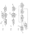
- Figure 1 is a simplified block diagram of a system at a voice encoder for encoding voice signals into a digital form for transmission to a voice decoder;
- Figure 2 is a simplified block diagram of a system at a voice decoder for receiving the digital signals from the voice encoder and for decoding the digital signals to reproduce the voice signals;
- Figure 3 is a block diagram in increased detail of a portion of the voice encoder shown in Figure 1 and shows how the voice encoder determines and encodes the amplitudes and phases of the harmonics in successive time frames;
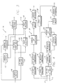
- Figure 4 is a block diagram of another portion of the voice encoder and shows how the voice encoder determines the pitch frequency of the voice signals in the successive time frames;
- Figure 5 is a block diagram of the voice decoder shown in Figure 2 and shows the decoding system in more detail than that shown in Figure 2;
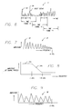
- Figure 6 is a schematic diagram of the voice signals to be encoded in successive time frames and further illustrates how the time frames overlap;
- Figure 7 is a diagram schematically illustrating signals produced in a typical time frame to represent different frequencies after the voice signals in the time frame have been frequency transformed as by a Fourier frequency analysis;
- Figure 8 illustrates the characteristics of a low pass filter for operating upon the frequency signals such as shown in Figure 7;
- Figure 9 is a diagram schematically illustrating a spectrum of frequency signals after the frequency signals of Figure 7 have been passed through a low pass filter with the characteristics shown in Figure 8;
- Figure 10 is a diagram illustrating one step involving the use of a Hamming window analysis in precisely determining the characteristics of each harmonic frequency in the voice signals in each time frame;
- Figure 11 indicates the amplitude pattern of an individual frequency as a result of using the Hamming window analysis shown in Figure 10;
- Figure 12 illustrates the techniques used to determine the amplitude and phase of each harmonic in the voice signals in each time frame with greater precision than in the prior art;
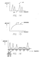
- Figure 13 illustrates the relative amplitude values of the logarithms of the different harmonics in the voice signals in each time frame and the selection of the harmonic with the peak amplitude;
- Figure 14 indicates the logarithmic harmonic signals of Figure 13 after the amplitudes of the different harmonics have been converted to indicate their amplitude difference relative to the peak amplitude shown in Figure 13;
- Figure 15 schematically indicates the effect of a companding operation on the signals shown in Figure 14; and
- Figure 16 illustrates how the frequency signals in different frequency slots or bins in each time frame are analyzed to provide voiced (binary "I") and unvoiced (binary "0") signals in such time frame.
-
- In one embodiment of the invention, voice signals are indicated at 10 in Figure 6. As will be seen, the voice signals are generally variable with time and generally do not have a fully repetitive pattern. The system of this invention includes a block segmentation stage 12 (Figure 1) which separates the signals into time frames 14 (Figure 6) each preferably having a suitable time duration such as approximately thirty two milliseconds (32 ms.). Preferably the
time frames 14 overlap by a suitable period of time such as approximately twelve milliseconds (12 ms.) as indicated at 16 in Figure 1. The overlap 16 is provided in thetime frames 14 because portions of the voice signals at the beginning and end of eachtime frame 14 tend to become distorted during the processing of the signals in the time frame relative to the portions of the signals in the middle of the time frame. - The
block segmentation stage 12 in Figure 1 is included in a voice coder generally indicated at 18 in Figure 1. A pitch estimation stage generally indicated at 20 estimates the pitch or fundamental frequency of the voice signals in each of thetime frames 14 in a number of different ways each providing an added degree of precision and/or confidence to the estimation. The stages estimating the pitch frequency in different ways are shown in Figure 4. - The voice signals in each
time frame 14 also pass tostage 22 which provides a frequency transform such as a Fourier frequency transform on the signals. The resultant frequency signals are generally indicated at 24 in Figure 7. Thesignals 24 in eachtime frame 14 then pass to acoder stage 26. Thecoder stage 26 determines the amplitude and phase of the different frequency components in the voice signals in eachtime frame 14 and converts these determinations to a binary form for transmission to a voice decoder such as shown in Figures 2 and 5. The stages for providing the determination of amplitudes and phases and for converting these determinations to a form for transmission to the voice decoder of Figure 2 are shown in Figure 3. - Figure 4 illustrates in additional detail the
pitch estimation stage 20 shown in Figure 1. Thepitch estimation stage 20 includes astage 30 for receiving the voice signals on aline 32 in a first one of thetime frames 14 and for performing a frequency transform on such voice signals as by a Fourier frequency transform. Similarly, astage 34 receives the voice signals on aline 36 in thenext time frame 14 and performs a frequency transform such as by a Fourier frequency transform on such voice signals. In this way, thestage 30 performs frequency transforms on the voice signals in alternate ones of thesuccessive time frames 14 and thestage 34 performs frequency transforms on the voice signals in the other ones of the time frames. Thestages signals 24 in Figure 7. - The frequency signals from the
stage 30 pass to astage 38 which performs a logarithmic calculation on the magnitudes of these frequency signals. This causes the magnitudes of the peak amplitudes of thesignals 24 to be closer to one another than if the logarithmic calculation were not provided. Harmonic gap measurements in astage 40 are then provided on the logarithmic signals from thestage 38. The harmonic gap calculations involve a determination of the difference in amplitude between the peak of each frequency signal and the trough following the signal. This is illustrated in Figure 8 at 42 for a peak amplitude for one of the frequency signals 24 and at 44 for a trough following thepeak amplitude 40. In determining the difference between the peak amplitudes such as the amplitude 42 and the troughs such as the trough 44, the positions in the frequency spectrum around the peak amplitude and the trough are also included in the determination. The frequency signal providing the largest difference between the peak amplitude and the following trough in the frequency signals 24 constitutes one estimation of the pitch frequency of the voice signals in thetime frame 14. This estimation is where the peak amplitude of such frequency signal occurs. - As will be appreciated, female voices are higher in pitch frequency than male voices. This causes the number of harmonic frequencies in the voice signals of females to be lower than those in the voice signals of male voices. However, since the pitch frequency in the voice signals of a male is low, the spacing in time between successive signals at the pitch frequency in each
time frame 14 may be quite long. Because of this, only two (2) or three (3) periods at the pitch frequency may occur in eachtime frame 14 for a male voice. This limits the ability to provide accurate determinations of pitch frequency for a male voice. - In providing a harmonic gap calculation, the
stage 40 always provides a determination with respect to the voice frequencies of voices whether the voice is that of a male or a female. However, when the voice is that of a female, thestage 40 provides an additional calculation with particular attention to the pitch frequencies normally associated with female voices. This additional calculation is advantageous because there are an increased number of signals at the pitch frequency of female voices in eachtime frame 14, thereby providing for an enhancement in the estimation of the pitch frequency when an additional calculation is provided in thestage 40 for female voices. - The signals from the
stage 40 for performing the harmonic gap calculation pass to astage 46 for providing a pitch match with a restored harmonic synthesis. This restored harmonic synthesis will be described in detail subsequently in connection with the description of thetransform coder stage 26 which is shown in block form in Figure 1 and in a detailed block form in Figure 3. Thestage 46 operates to shift the determination of the pitch frequency from thestage 66 through a relatively small range above and below the determined pitch frequency to provide an optimal matching with such harmonic synthesis. In this way, the determination of the pitch frequency in each time frame is refined if there is still any ambiguity in this determination. As will be appreciated, a sequence of 512 successive frequencies can be represented in a binary sequence of nine (9) binary bits. Furthermore, the pitch frequency of male and female voices generally falls in this binary range of 512 discrete frequencies. As will be seen subsequently, the pitch frequency of the voice signals in eachtime frame 14 is indicated by nine (9) binary bits. - The signals from the
stage 46 are introduced to astage 48 for determining a harmonic difference. In thestage 48, the peak amplitudes of all of the odd harmonics are added to provide one cumulative value and the peak amplitudes of all of the even harmonics are added to provide another cumulative value. The two cumulative values are then compared. When the cumulative value for the even harmonics exceeds the cumulative value for the odd harmonics by a particular value such as approximately fifteen per cent (15%), the lowest one of the even harmonics is selected as the pitch frequency. Otherwise, the lowest one of the odd harmonics is selected. - The voice signals on the lines 32 (for the alternate time frames 14) and 36 (for the remaining time frames 14) are introduced to a low pass filter 52. The filter 52 has characteristics for passing the full amplitudes of the signal components in the pairs of successive time frames with frequencies less than approximately one thousand hertz (1000Hz). This is illustrated at 54a in figure 8. As the frequency components increase above one thousand hertz (1000Hz), progressive portions of these frequency components are filtered. This is illustrated at 54b in Figure 8. As will be seen in Figure 8, the filter has a flat response 54a to approximately one thousand hertz (1000Hz) and the response then decreases relatively rapidly between a range of frequencies such as to approximately eighteen hundred hertz (1800Hz). The lowpass filtered signal is subsampled by a factor of two - i.e., alternate samples are discarded. This is consistent with the theory since the frequencies above 2000Hz have been nearly diminished.
- The signals passing through the low pass filter 52 in Figure 4 are introduced to a
stage 56 for providing a frequency transform such as a Fourier frequency transform. By filtering increasing amplitudes of the signals with progressive increases in frequency above one thousand Hertz (1000Hz), the frequency transformed signals generally indicated at 58 in Figure 9 are spread out more in the frequency spectrum than the signals in Figure 7. This may be seen by comparing the frequency spectrum of the signals produced in Figure 9 as a result of the filtering in comparison with the frequency spectrum in Figure 7. The spreading of the frequency spectrum in Figure 9 causes the resolution in the signals to be enhanced. For example, the frequency resolution may be increased by a factor of two (2). - The signals from the low pass filter 52 are also introduced to a
stage 60 for providing a Cepstrum computation or analysis. Stages providing Cepstrum computations or analyses are well known in the art. In such a stage, the highest peak amplitude of the filtered signals in each pair ofsuccessive time frames 14 is determined. This signal may be indicated at 62 in Figure 6. The time between thissignal 62 and asignal 64 with the next peak amplitude in the pair ofsuccessive time frames 14 may then be determined. This time is indicated at 66 in Figure 6. Thetime 66 is then translated into a pitch frequency for the signals in the pair of successive time frames 14. - The determination of the pitch frequency in the
stage 60 is introduced to astage 66 in Figure 4. Thestage 66 receives the signals from astage 68 which performs logarithmic calculations on the amplitudes of the frequency signals from thestage 56 in a manner similar to that described above for thestage 38. Thestage 66 provides harmonic gap calculations of the pitch frequency in a manner similar to that described above for thestage 40. Thestage 66 accordingly modifies (or provides a refinement in) the determination of the frequency from thestage 60 if there is any ambiguity in such determination. Alternatively, thestage 60 may be considered to modify (or provide a refinement in) the signals from thestage 66. As will be appreciated, there may be an ambiguity in the determination of the pitch frequency from thestage 60 if the time determination should be made from a different peak amplitude than the highest peak amplitude in the two (2) successive time frames or if the time between the successive peaks does not provide a precise indication of the pitch frequency. - As previously described, the
stage 34 provides a frequency transform such as a Fourier frequency transform on the signals in theline 36 which receives the voice signals in the second of the two (2)successive time frames 14 in each pair. The frequency signals from thestage 34 pass to astage 70 which provides a log magnitude computation or analysis corresponding to the log magnitude computations or analyses provided by thestages stage 70 in turn pass to thestage 66 to provide a further refinement in the determination of the pitch frequency for the voice signals in each pair of two (2) successive time frames 14. - The signals from the
stage 66 pass to astage 74 which provides a pitch match with a restored harmonic synthesis. This restored harmonic synthesis will be described in detail subsequently in connection with the description of thetransform coder stage 26 which is shown in block form in Figure 1 and in a detailed block form in Figure 3. The pitch match performed by thestage 74 corresponds to the pitch match performed by thestage 46. Thestage 74 operates to shift the determination of the pitch frequency from thestage 66 through a relatively small range above and below this determined pitch frequency to provide an optimal matching with such harmonic synthesis. In this way, the determination of the pitch frequency in each time frame is refined if there is still any ambiguity in this determination. - A
stage 78 receives the refined determination of the pitch frequency from thestage 74. Thestage 78 provides a further refinement in the determination of the pitch frequency in each time frame if there is still any ambiguity in such determination. Thestage 78 operates to accumulate the sum of the amplitudes of all of the odd harmonics in the frequency transform signals obtained by thestage 74 and to accumulate the sum of the amplitudes of all of the even harmonics in such even harmonics exceeds the accumulated sum of all of the odd harmonics by a particular magnitude such as fifteen percent (15%) of the accumulated sum of the odd harmonics, the lowest frequency in the even harmonics is chosen as the pitch frequency. If the accumulated sum of the even harmonics does not exceed the accumulated sum of the odd harmonics by this threshold, the lowest frequency in the odd harmonics is selected as the pitch frequency. The operation of theharmonic difference stage 78 corresponds to the operation of theharmonic difference stage 48. - The signals from the
stage 78 pass to apitch interpolation stage 80. Thepitch interpolation stage 80 also receives through a line 82 signals which represent the signals obtained from thestage 78 for one (1) previous frame. For example, if the signals passing to thestage 80 from thestage 78 represent the pitch frequency determined intime frames frame 0. Thestage 80 interpolates between the pitch frequency determined for thetime frame 0 and thetime frames time frame 1. This information is introduced to thestage 40 to refine the determination of the pitch frequency in that stage for thetime frame 1. - The
pitch interpolation stage 80 also employs heuristic techniques to refine the determination of pitch frequency for thetime frame 1. For example, thestage 80 may determine the magnitude of the power in the frequency signals for low frequencies in thetime frames time frame 0. Thestage 80 may also determine the ratio of the cumulative magnitude of the power in the frequency signals at low frequencies (or the cumulative magnitude of the amplitudes of such signals) in such time frames relative to the cumulative magnitude of the power (or the cumulative magnitude of the amplitudes) of the high frequency signals in such time frames. These factors, as well as other factors, may be used in thestage 80 in refining the pitch frequency for thetime frame 1. - The output from the
pitch interpolation stage 80 is introduced to the harmonicgap computation stage 40 to refine the determination of the pitch frequency in thestage 38. As previously described, this determination is further refined by thepitch match stage 46 and theharmonic difference stage 48. The output from theharmonic difference stage 48 indicates in nine (9) binary bits the refined determination of the pitch frequency for thetime frame 1. These are the first binary bits that are transmitted to the voice decoder shown in Figure 2 to indicate to the voice decoder the parameters identifying the characteristics of the voice signals in thetime frame 1. In like manner, theharmonic difference stage 78 indicates in nine (9) binary bits the refined estimate of the pitch frequency for thetime frame 2. These are the first binary bits that are transmitted to the voice decoder shown in Figure 2 to indicate the parameters of the voice signals in thetime frame 2. As will be appreciated, the system shown in Figure 4 and described above operates in a similar manner to determine and code the pitch frequency in successive pairs of time frames such astime frames 3 and 4, 5 and 6, etc. - The
transform coder 26 in Figure 1 is shown in detail in Figure 3. Thetransform coder 26 includes astage 86 for determining the amplitude and phase of the signals at the fundamental (or pitch) frequency and the amplitude and phase of each of the harmonic signals. This determination is provided in a range of frequencies to approximately four KiloHertz (4 KHz) bandwidth. The determination is limited to approximately four KiloHertz (4 KHz) because the limit of four thousand hertz (4Kz) corresponds to the limit of frequencies encountered in the telephone network as a result of adapted standards. - As a first step in determining the amplitude and phase of the pitch frequency and the harmonics in each
time frame 14, thestage 86 divides the frequency range to four thousand Hertz (4000Hz) into a number of frequency blocks such as thirty (32). Thestage 86 then divides each frequency block into a particular number of grids such as approximately sixteen (16). Several frequency blocks 96 and thegrids 98 for one of the frequency blocks are shown in Figure 12. Thestage 86 knows, from the determination of the pitch frequency in eachtime frame 14, the frequency block in which each harmonic frequency is located. Thestage 86 then determines the particular one of the sixteen (16) grids in which each harmonic is located in its respective frequency block. By precisely determining the frequency of each harmonic signal, the amplitude and phase of each harmonic signal can be determined with some precision, as will be described in detail subsequently. - As a first step in determining with some precision the frequency of each harmonic signal in the Fourier frequency transform produced in each
time frame 14, thestage 86 provides a Hamming window analysis of the voice signals in eachtime frame 14. A Hamming window analysis is well known in the art. In a Hamming window analysis, the voice signals 92 (Figure 10) in eachtime frame 14 are modified as by a curve having a dome-shapedpattern 94 in Figure 10. As will be seen, the dome-shapedpattern 94 has a higher amplitude with progressive positions toward the center of thetime frame 14 then toward the edges of the time frame. This relative de-emphasis of the voice signals at the opposite edges of eachtime frame 14 is one reason why the time frames are overlapped as shown in Figure 6. - When the
Hamming pattern 94 is used to modify the voice signals in eachtime frame 14 and a Fourier transform is made of the resultant pattern for an individual frequency, a frequency pattern such as shown in Figure 11 is produced. This frequency pattern may be produced for one of the sixteen (16) grids in the frequency block in which a harmonic is determined to exist. Similar frequency patterns are determined for the other fifteen (15) grids in the frequency block. The grid which is nearest to the location of a given harmonic is selected. By determining the particular one of the sixteen (16) grids in which the harmonic is located, the frequency of the harmonic is selected with greater precision than in the prior art. - In this way, the amplitude and phase are determined for each harmonic in each
time frame 14. The phase of each harmonic is encoded for eachtime frame 14 by comparing the harmonic frequency in eachtime frame 14 with the harmonic frequency in the adjacent time frames. As will be be appreciated, changes in the phase of a harmonic signal result from changes in frequency of that harmonic signal. Since the period in eachtime frame 14 is relatively short and since there is a time overlap between adjacent time frames, any changes in pitch frequency in successive time frames may be considered to result in changes in phase. - As a result of the analysis as discussed above, pairs of signals are generated for each harmonic frequency, one of these signals representing amplitude and the other representing phase. These signals may be represented as a1⊘1, a2⊘2, a3⊘3, etc.
In this sequence
a1, a2, a3, etc. represent the amplitudes of the signals at the fundamental frequency and the second, third, etc. harmonics of the pitch frequency signals in each time frame; and
⊘1, ⊘2, ⊘3, etc. represent the phases of the signals at the fundamental frequency and the second, third, etc. harmonics in eachtime frame 14. - Although the amplitude values a1, a2, a3, etc., and the phase values ⊘1, ⊘2, ⊘3, etc. may represent the parameters of the signals at the fundamental pitch frequency and the different harmonics in each
time frame 14 with some precision, these values are not in a form which can be transmitted from thevoice coder 18 shown in Figure 1 to a voice decoder generally indicated at 100 in Figure 2. The circuitry shown in Figure 3 provides a conversion of the amplitude values a1, a2, a3, etc., and the phase values ⊘1, ⊘2, ⊘3, etc. to a meaningful binary form for transmission to thevoice decoder 100 in Figure 2 and for decoding at the voice decoder. - To provide such a conversion, the signals from the
harmonic analysis stage 86 in Figure 3 are introduced to astage 104 designated as "spectrum shape calculation". Thestage 104 also receives the signals from astage 102 which is designated as "get band amplitude". The input to thestage 102 corresponds to the input to thestage 86. Thestage 102 determines the frequency band in which the amplitude of the signals occurs. - As a first step in converting the amplitudes a1, a2, a3, etc., to meaningful and simplified binary values for transmission to the
voice decoder 100, the logarithms of the amplitude values a1, a2, a3, etc., are determined in thestage 104 in Figure 3. Taking the logarithm of these amplitude values is desirable because the resultant values become compressed relative to one another without losing their significance with respect to one another. The logarithms can be with respect to any suitable base value such as a base value of two (2) or a base value of ten (10). - The logarithmic values of amplitude are then compared in the
stage 104 in Figure 3 to select the peak value of all of these amplitudes. This is indicated schematically in Figure 13 where the different frequency signals and the amplitudes of these signals are indicated schematically and the peak amplitude of the signal with the largest amplitude is indicated at 106. The amplitudes of all of the other frequency signals are then scaled with thepeak amplitude 106 as a base. In other words, the difference between thepeak amplitude 106 and the magnitude of each of the remaining amplitude values a1, a2, a3, etc., is determined. These difference values are indicated schematically at 108 in Figure 14. - The difference values 108 in Figure 14 are next companded. A companding operation is well known in the art. In a companding operation, the difference values shown in Figure 14 are progressively compressed for values at the high end of the amplitude range. This is indicated schematically at 110 in Figure 15. In effect, the amplitude values closest to the peak values in Figure 13 are emphasized by the companding operation relative to the amplitudes of low value in Figure 13.
- As the next step in converting the amplitude values a1, a2, a3, etc., to a meaningful and simplified binary form, the number of such values is limited in the
stage 104 to a particular value such as forty five (45) if the amplitude values exceed forty five (45). This limit is imposed by disregarding the harmonics having the highest frequency values. Disregarding the harmonics of the highest frequency does not result in any deterioration in the faithful reproduction of sound since most of the information relating to the sound is contained in the low frequencies. - As a next step, the number of harmonics is limited in the
stage 104 to a suitable number such as sixteen (16) if the number of harmonics is between sixteen (16) and twenty (20). This is accomplished by eliminating alternate ones of the harmonics at the high end of the frequency range if the number of harmonics is between sixteen (16) and twenty (20). If the number of harmonics is less than sixteen (16), the harmonics are expanded to sixteen (16) by pairing successive harmonics at the upper frequency end to form additional harmonics between the paired harmonics and by interpolating the amplitudes of the additional harmonics in accordance with the amplitudes of the paired harmonics. - In like manner, if the number of harmonics is greater than twenty four (24), alternate ones of the harmonics are eliminated at the high end of the frequency range until the number of harmonics is reduced to twenty four (24). If the number of harmonics is between twenty one (21) and twenty four (24), the number of harmonics is increased to twenty four (24) by pairing successive harmonics at the upper frequency end to form additional harmonics between the paired harmonics and by interpolating the amplitudes of the additional harmonics in accordance with the amplitudes of the paired harmonics.
- After the number of harmonics has been limited to sixteen (16) or twenty four (24) depending upon the number of harmonics produced in the Fourier frequency transform, a discrete cosine transform is provided in the
stage 104 on the limited number of harmonics. The discrete cosine transform is well known to be advantageous for compression of correlated signals such as in a spectrum shape. The discrete cosine transform is taken over the full range of sixteen (16) or twenty four (24) harmonics. This is different from the prior art because the prior art obtains several discrete cosine transforms of the harmonics, each limited to approximately eight (8) harmonics. However, the prior art does not limit the total number of frequencies in the transform such as is provided in the system of this invention when the number is limited to sixteen (16) or twenty four (24). - The results obtained from the discrete cosine transform discussed in the previous paragraph are subsequently converted by a
stage 110 to a particular number of binary bits to represent such results. For example, the results may be converted to forty eight (48), sixty four (64) or eighty (80) binary bits. The number of binary bits is preselected so that thevoice decoder 100 will know how to decode such binary bits. In coding the results of the discrete cosine transform, a greater emphasis is preferably placed on the low frequency components of the discrete cosine transform relative to the high frequency components. For example, the number of binary bits used to indicate the successive values from the discrete cosine transform may illustratively be asequence voice decoder 100 in Figure 2 after the transmission of the nine (9) binary bits representing the pitch or fundamental frequency. - A
stage 112 in Figure 3 receives the signals representing the discrete cosine transform from thestage 104 and reconstructs these signals to a form corresponding to the Fourier frequency transform signals introduced to thestage 86. As a first step in this reconstruction, thestage 112 receives the signals from thestage 104 and provides an inverse of a discrete cosine transform. Thestage 112 then expands the number of harmonics to coincide with the number of harmonics in the Fourier frequency transform signals introduced to thestage 86. Thestage 112 does this by interpolating between the amplitudes of successive pairs of harmonics in the upper end of the frequency range. Thestage 112 then performs a decompanding operation which is the inverse of the companding operation performed by thestage 110. The signals are now in a form corresponding to that shown in Figure 14. - To convert the signals to the form shown in Figure 13, a difference is determined between the
peak amplitude 106 shown in Figure 13 for each harmonic and the amplitude shown in Figure 14 for such harmonic. The resultant amplitudes correspond to those shown in Figure 13, assuming that each step in the reconversion provided in thestage 112 provides ideal calculations. The signals corresponding to those shown in Figure 13 are then processed in thestage 112 to remove the logarithmic values and to obtain Fourier frequency transform signals corresponding to those introduced to thestage 86. - The reconstructed Fourier frequency transform signals from the
stage 112 are introduced to astage 116. The Fourier frequency transform signals passing to thestage 86 are also introduced to thestage 116 for comparison with the reconstructed Fourier frequency transform signals in thestage 112. To provide this comparison, the Fourier frequency transform signals from each of thestages bins 118 as shown in Figure 16. Each of the frequency slots orbins 118 has a different range of frequencies than the other frequency slots or bins. The number of frequency slots or bins is arbitrary but twelve (12) may be preferable. It will be appreciated that more than one (1) harmonic may be located in each time slot orbin 118. - The
stage 116 compares the amplitudes of the Fourier frequency transform signals from thestage 112 in each frequency slot orbin 118 and the signals introduced to thestage 86 for that frequency slot or bin. If the amplitude match is within a particular factor for an individual one of the time slot orbin 118, thestage 116 produces a binary "1" for that time slot or bin. If the amplitude match is not within the particular factor for an individual time slot orbin 118, thestage 116 produces a binary "0" for that time slot or bin. The particular factor may depend upon the pitch frequency and upon other quality factors. - Figure 16 illustrates when a binary "1" is produced in a time slot or
bin 118 and when a binary "0" is produced in a time slot orbin 118. As will be seen, when the correlation between the signals in thestages bin 118. However, when the correlation is low as indicated by a signal of low amplitude, a binary "0" is produced for a time slot orbin 118. In effect, thestage 116 provides a binary "1" only in the frequency slots orbins 118 where thestage 104 has been successful in converting the frequency indications in thestage 86 to a form closely representing the indications in thestage 86. In the time slots orbins 118 where such conversion has not been successful, thestage 116 provides a binary "0". - Some post processing may be provided in the
stage 116 to reconsider whether the binary value for a time slot orbin 118 is a binary "1" or a binary "0". For example, if the binary values for successive time slots or bins is "000100", the binary value of "1" in this sequence in the time frame 114 under consideration may be reconsidered in thestage 116 on the basis of heuristics. Under such circumstances, the binary value for this time slot or bin in theadjacent time frames 14 could also be analyzed to reconsider whether the binary value for this time slot or bin in thetime frame 14 under consideration should actually be a binary "0" rather than a binary "1". Similar heuristic techniques may also be employed in thestage 116 to reconsider whether the binary value of "0" in the sequence of 11101 should be a binary "1" rather than a binary "0". - The twelve (12) binary bits representing a binary "1" or a binary "0" in each of the twelve (12) time slots or bins (118) in each
time frame 14 are introduced to thestage 110 in Figure 3 for transmission to thevoice decoder 100 shown in Figure 1. These twelve (12) binary bits in each time frame may be produced immediately after the nine (9) binary bits representing the pitch frequency and may be followed by the 48, 64 or 80 binary bits representing the amplitudes of the different harmonics. A binary "1" in any of these twelve (12) time bins orslots 118 may be considered to represent voiced signals for such time bin or slot. A binary "0" in any of these twelve (12) time bins orslots 118 may be considered to represent unvoiced signals for such time bin or slot. For a time bin or slot where unvoiced signals are produced, the amplitude of the harmonic or harmonics in such time bin or slot may be considered to represent noise at an average of the amplitude levels of the harmonic or harmonics in such time slot or bin. - The binary value representing the voiced (binary "1") or unvoiced (binary "0") signals from the
stage 116 are introduced to thestage 104. For the time slots orbins 118 where a binary "1" has been produced by thestage 116, thestage 104 produces binary signals representing the amplitudes of the signals in the time slots or bins. These signals are encoded by thestage 110 and are transmitted through a line 124 to the voice decoder shown in Figure 2. When a binary "0" is produced by thestage 116 for a time slot orbin 118, thestage 104 produces "noise" signals having an amplitude representing the average amplitude of the signals in the time slot or bin. These signals are encoded by thestage 110 into binary form and are transmitted through the line 124 to the voice decoder. - The phase signals ⊘1, ⊘2, ⊘3, etc. for the successive harmonics in each
time frame 14 are converted in astage 120 in Figure 3 to a form for transmission to thevoice decoder 100. If the phase of the signals for a harmonic has at least a particular continuity in aparticular time frame 14 with the phase of the signals for the harmonic in the previous time frame, the phase of the signal for the harmonic in the particular time frame is predicted from the phase of the signal for the harmonic in the previous time frame. The difference between the actual phase and this prediction is what is transmitted for the phase of the signal for the harmonic in the particular time frame. For a particular number of binary bits to represent such harmonic, this difference prediction can be transmitted with more accuracy to thevoice decoder 100 than the information representing the phase of the'signal constituting such harmonic in such particular time frame. However, if the phase of the signal for such harmonic in suchparticular time frame 14 does not have at least the particular continuity with the phase of the signal for such harmonic in the previous time frame, the phase of the signal for such harmonic in such particular time frame is transmitted to thevoice decoder 100. - As with the amplitude information, a particular number of binary bits is provided to represent the phase, or the difference prediction of the phase, for each harmonic in each time frame. The number of binary bits representing the phases, or the difference predictions of the phases, of the harmonic signals in each
time frame 14 is computed as the total bits available for the time frame minus the bits already used for prior information. The phases, or the difference predictions of the phases, of the signals at the lower harmonic frequencies are indicated in a larger number of binary bits than the phases of the signals, or the difference predictions of the phases, of the signals at the higher frequencies. - The binary bits representing the phases, or the predictions of the phases, for the signals of the different harmonics in each
time frame 14 are produced in astage 130 in Figure 3, this stage being designated as "phase encoding". The binary bits representing the phases, or the prediction of the phases, of the signals at the different harmonics in eachtime frame 14 are transmitted through aline 132 in eachtime frame 14 after the binary bits representing the amplitudes of the signals at the different harmonics in each time frame. - The
voice decoder 100 is shown in a simplified block form in Figure 2. Thevoice decoder 100 includes aline 140 which receives the coded voice signals from thevoice coder 18. A transform decoder stage generally indicated at 142 operates upon these signals, which indicate the pitch frequency and the amplitudes and phases of the pitch frequency and the harmonics, to recover the signals representing the pitch frequency and the harmonics. Astage 144 performs an inverse of a Fourier frequency transform on the recovered signals representing the pitch frequency and the harmonics to restore the signals to a time domain form. These signals are further processed in thestage 144 by compensating for the effects of theHamming window 94 shown in Figure 10. In effect, thestage 144 divides by theHamming window 94 to compensate for the multiplication by the Hamming window in thevoice coder 18. The signals in the time domain form are then separated in astage 146 into the voice signals in thesuccessive time frames 14 by taking account of the time overlap still remaining in the signals from thestage 144. This time overlap is indicated at 16 in Figure 6. - The
transform decoder stage 142 is shown in block form in additional detail in Figure 5. Thetransform decoder 142 includes astage 150 for receiving the 48, 64 or 80 bits representing the amplitudes of the pitch frequency and the harmonics and for decoding these signals to determine the amplitudes of the pitch frequency and the harmonics. In decoding such signals, thestage 150 performs a sequence of steps which are in reverse order to the steps performed during the encoding operation and which are the inverse of such steps. As a first step in such decoding, thestage 150 performs the inverse of a discrete cosine transform on such signals to obtain the frequency components of the voice signals in eachtime frame 14. - As will be appreciated, the number of signals produced as a result of the inverse discrete cosine transform depends upon the number of the harmonics in the voice signals at the
voice coder 18 in Figure 1. The number of harmonics is then expanded or compressed to the number of harmonics at thevoice coder 18 by interpolating between successive pairs of harmonics at the upper end of the frequency range. The number of harmonics in the voice signals at thevoice coder 18 in each time frame can be determined in thestage 18 from the pitch frequency of the voice signals in that time frame. As will be appreciated, if an expansion in the number of harmonics occurs, the amplitude of each of these interpolated signals may be determined by averaging the amplitudes of the harmonic signals with frequencies immediately above and below ' the frequency of this interpolated signal. - A decompanding operation is then performed on the expanded number of harmonic signals. This decompanding operation is the inverse of the companding operation performed in the
transform coder stage 26 shown in Figure 1 and in detail in Figure 3 and shown schematically in Figure 15. The decompanded signals are then restored to a base of zero (0) as a reference from the peak amplitude of all of the harmonic signals as a reference. This corresponds to a conversion of the signals from the form shown in Figure 14 to the form shown in Figure 13. - A
phase decoding stage 152 in Figure 5 receives the signals from theamplitude decoding stage 150. Thephase decoding stage 152 determines the phases ⊘1, ⊘2, ⊘3, etc. for the successive harmonics in eachtime frame 14. Thephase decoding stage 152 does this by decoding the binary bits indicating the phase of each harmonic in eachtime frame 14 or by decoding the binary bits indicating the difference predictions of the phase for such harmonic insuch time frame 14. When thephase decoding stage 152 decodes the difference prediction of the phase of a harmonic in aparticular time frame 14, it does so by determining the phase for such harmonic in theprevious time frame 14 and by modifying such phase in theparticular time frame 14 in accordance with such phase prediction for such time frame. - The decoded phase signals from the
phase decoding stage 152 are introduced to a harmonic reconstruction stage 154 as are the signals from theamplitude decoding stage 150. The harmonic reconstruction stage 154 operates on the amplitude signals from theamplitude decoding stage 150 and the phase signals from thephase decoding stage 152 for eachtime frame 14 to reconstruct the harmonic signals in such time frame. The harmonic reconstruction stage 154 reconstructs the harmonics in eachtime frame 14 by providing the frequency pattern (Figure 11) at different frequencies to determine the pattern at such different frequencies of the signals introduced to the stage 154. - The signals from the harmonic reconstruction stage 154 are introduced to a harmonic synthesis stage 158. The stage 158 operates to synthesize the Fourier frequency coefficients by positioning the harmonics and multiplying these harmonics by the Fourier frequency transform of the
Hamming window 94 shown in Figure 10. The signals from the harmonic synthesis stage 158 pass to astage 160 where the unvoiced signals (binary "0") in the time slots or bins 118 (Figure 16) are provided on a line 167 and are processed. In these frequency bins orslots 118, signals having a noise level represented by the average amplitude level of the harmonic signals in such time slots or bins are provided on the line 168. These signals are processed in thestage 160 to recover the frequency components in such time slots. As previously indicated, the signals from thestage 160 are subjected in thestage 144 in Figure 2 to the inverse of the Fourier frequency transform. The resultant signals are in the time domain and are modified by the inverse of theHamming window 94 shown in Figure 10. The signals from thestage 144 accordingly represent the voice signals in the successive time frames 14. The overlap in thesuccessive time frames 14 is removed in thestage 146 to reproduce the voice signals in a continuous pattern. - The apparatus and methods described above have certain important advantages. They employ a plurality of different techniques to determine, and then refine the determination of, the pitch frequency in each of a sequence of overlapping time frames. They employ refined techniques to determine the amplitude and phase of the pitch frequency signals and the harmonic signals in the voice signals of each time frame. They also employ refined techniques to convert the amplitude and phase of the pitch frequency signals and the harmonic signals to a binary form which accurately represents the amplitudes and phases of such signals.
- The apparatus and methods described in the previous paragraph are employed at the voice coder. The voice decoder employs refined techniques which are the inverse of those, and are in reverse order to those, at the voice coder to reproduce the voice signals. The apparatus and methods employed at the voice decoder are refined in order to process, in reverse order and on an inverted basis, the encoded signals to recover the voice signals introduced to the voice encoder.
- Although this invention has been disclosed and illustrated with reference to particular embodiments, the principles involved are susceptible for use in numerous other embodiments which will be apparent to persons skilled in the art. The invention is, therefore, to be limited only as indicated by the scope of the appended claims.
Claims (40)
- An encoder (18) for coding input voice signals, including a block segmentation means (12) for dividing the voice signals into successive time frames (14), pitch estimation means (20), responsive to the block segmentation means (12), for estimating the pitch of the voice signals in each of the time frames (14), frequency transform means (22), responsive to the block segmentation means (12), for providing a frequency transform on the voice signals in each of the time frames (14), and transform coder means (26), responsive to the pitch estimation means (20) and the frequency transform means (22), for determining the amplitude and phase of the different frequency components in the voice signal in each time frame (14) and converting these determinations into binary form, wherein the pitch estimation means (20) is,
receiving means (32,36) for combining the voice signals in successive pairs of time frames (14) to obtain an enhanced resolution of the voice signals in each time frame (14),
frequency transforming means (30,34), responsive to the receiving means (32,36), for obtaining a frequency transform of the voice signals into frequency signals in each of the successive pairs of time frames (14),
logarithm computation means (38,70), responsive to the frequency transforming means (30,34), for performing a logarithmic calculation of the magnitudes of the frequency signals,
filtering means (52), responsive to the receiving means (32,36), for passing the voice signals in each of the successive pairs of frames in a first particular range of frequencies and for providing a progressive filtering of such voice signals for progressive frequencies above the first particular range in each of the successive pairs of time frames, and
frequency transformation means (56), responsive to the filtering means (52), for operating upon the signals for determining the pitch frequency of the voice signals in each successive pair of time frames (14). - An encoder (18) for coding input voice signals in accordance with claim 1, wherein the pitch estimation means (20) is further,
characterized by
Cepstrum computation means (60), responsive to the filtering means (52), for providing a Cepstrum determination of the voice pitch frequency in the successive time frames (14), and
first harmonic gap computation means (66), responsive to the Cepstrum computation means (60), for determining the difference in amplitude between the peak (42) of the frequency signal and the trough (44) following the frequency signal. - An encoder (18) for coding input voice signals in accordance with claim 2, wherein the pitch estimation means (20) is further,
characterized by
pitch interpolation means (80), responsive to the detection provided by the Cepstrum computation means (60) and the first harmonic gap computation means (66), for applying heuristic techniques to the Cepstrum determination and the difference in amplitude between a peak (42) of the frequency signal and a trough (44) following the frequency signal for redefining the determination of the voice pitch frequency. - An encoder (18) for coding input voice signals in accordance with claim 3, wherein the pitch interpolation means (80) is further,
characterized by
means for determining the magnitude of the power at low frequencies in the voice in the successive time frames (14), and
means for determining the ratio of the cumulative magnitude of the power of the low frequency signals relative to the cumulative magnitude of the power of the high frequency signals in the successive time frames (14). - An encoder (18) for coding input voice signals in accordance with any of claims 2 to 4, wherein the pitch estimation means (20) is further,
characterized by
means for selecting in each successive time frame (14) a particular number of signals with the highest peak amplitudes (62), and
second harmonic gap calculation means (40) for determining in each successive time frame (14) the amplitude difference between the peak amplitudes and the troughs between the peak amplitudes and the peak amplitude of the adjacent harmonic to refine the determination of the peak frequency by the Cepstrum computation means (60). - An encoder (18) for coding input voice signals in accordance with any of claims 2 to 5, wherein
the Cepstrum computation means (60) determines the location and amplitudes of the peaks of the signals in successive time frames. - An encoder (18) for coding input voice signals in accordance with any of claims 5 to 6, wherein the second harmonic gap computation means (40) is further,
characterized by
means for determining the pitch frequencies by the harmonic gap analysis in the pitch frequency range of low pitch voices whether the voices are low pitch or high pitch, and
means for determining the pitch frequencies in the pitch frequency range of high pitch voices by the harmonic gap analysis when the voice has a high pitch. - An encoder (18) for coding input voice signals in accordance with any of claims 5 to 7, wherein the pitch estimation means (20) is further,
characterized by
pitch matching means (46,74), responsive to the first and second harmonic gap computation means (40,66), for shifting the determination of the pitch frequency from
the logarithm magnitude computation means (36,70,68) through a small range above and below the determined pitch frequency to provide an optical matching with the harmonic synthesis. - An encoder (18) for coding input voice signals in accordance with claim 8, wherein the pitch estimation means (20) is further,
characterized by
harmonic difference calculation means (48,78), responsive to the pitch matching means (46,74), for accumulating the sum of the amplitudes of the odd and even harmonics in the frequency transform signals. - An encoder (18) for coding input voice signals in accordance with any of claims 1 to 9, wherein the transform coder means (26) is further,
characterized by
harmonic analysis means (86) for generating pairs of signals for each harmonic frequency, one of the signals representing amplitude and the other signal representing phase, and
converting means, responsive to the harmonic analysis means (86), for converting the pairs of signals into binary form for transmission. - An encoder (18) for coding input voice signals in accordance with claim 10, wherein the harmonic analysis means (86) is further,
characterized by
generating a range of frequencies with a band width of approximately 4 kilohertz. - An encoder (18) for coding input voice signals in accordance with either claim 10 or 11, wherein the harmonic analysis means (86) is further,
characterized by
means for determining the disposition of each harmonic in the frequency signals in individual ones of a plurality of time blocks and in individual ones of a plurality of grids within each time block. - An encoder (18) for coding input voice signals in accordance with claim 12, wherein the harmonic analysis means (86) is further,
characterized by
Hamming pattern (94) analysis means, for conducting a Hamming window analysis and frequency transformation such that a frequency pattern is generated for an individual grid within the time block. - An encoder (18) for coding input voice signals in accordance with any of claims 10 to 13, wherein the converting means is further,
characterized by
get band amplitude means (102) for determining the frequency band in which the amplitude of the signals occurs,
spectrum shape calculation means (104), responsive to the harmonic analysis means (86) and get band amplitude means (102), for completing a discrete cosine transformation upon a limited number of harmonics of the signals,
amplitude coding means (110), responsive to the spectrum shape calculation means (104), for converting the discrete cosine transformation into binary form,
phase calculation means (120), responsive to the harmonic analysis means (86), for converting phase signals into binary format, and
phase encoding means (130), responsive to the phase calculation means (120) and amplitude encoding means (110), for generating binary bits representing the phases for the signal of the different harmonics in each time frame (14). - An encoder (18) for coding input voice signals in accordance with claim 14, wherein the converting means is further,
characterized by
harmonic synthesis means (112), responsive to the spectrum shape calculation means (104), for reconstructing the discrete cosine transformation signal to a form corresponding to frequency transformation signals, and
harmonic correlation means (116), responsive to the harmonic synthesis means (112), pitch estimation means (20) and frequency transform means (22), and coupled to the spectrum shape calculation means (104), amplitude encoding means (110) and phase encoding means (130), for correlating the amplitudes of the frequency transformation signals, the frequency transform on the voice signals in each of the time frames (14), and the estimated pitch of the voice signals in each of the time frames (14). - A voice decoder (100) for recovering voice signals introduced to a voice coder (18) where the voice signals are processed in successive time frames (14) and wherein the voice signals in each time frame are subjected to a first frequency transform (22) to produce frequency signals in each time frame and where inversion signals are produced representing the difference between the peak amplitude of the frequency signals in each time frame and amplitude of the frequency signals in such time frame (20) and where the amplitudes of the inversion signals are companded and wherein a second frequency transform is performed on the companded signals and wherein the amplitudes of the signals in the second frequency transform are converted to digital signals (26), the voice decoder comprising input means (140) for receiving coded voice signals, transform decoder means (142), connected to the input means (140), for recovering the coded voice signals representing the pitch frequency and the harmonics, inverse transform means (144), coupled to the transform decoder means (142), for providing an inverse transformation in order to restore the signals to a time domain form, and smoothing means (146), coupled to the inverse transform means (144), for separating the signals in time domain form into voice signals, wherein the transform decoder means (142) is
characterized by
amplitude decoding means (150) for decoding the amplitudes of the pitch frequency and the harmonics,
phase decoding means (152), coupled to the amplitude decoding means (150), for determining the phases for the successive harmonics in each time frame,
harmonic reconstruction means (154), coupled to the amplitude decoding means (150) and the phase decoding means (152), for reconstructing the harmonics in each time frame,
harmonic synthesis means (158), coupled to the harmonic reconstruction means (154), for synthesizing the transformed frequency coefficients by positioning the harmonics and multiplying the harmonics by the frequency transform, and
unvoiced synthesis means (160), coupled to the harmonic synthesis means (158), for processing the unvoiced signals in frequency slots (118) to recover the frequency components in such frequency slots (118). - A voice decoder (100) in accordance with claim 16, wherein the number of frequency harmonics in each time frame is limited or expanded at the voice coder (18) to a particular value by eliminating or adding particular ones of the frequency signals at the high frequencies, and the transform decoder means (142) is further,
characterized by
the amplitude decoding means (150) operates to decompand the limited number of frequency signals. - A voice decoder (100) in accordance with either of claims 16 or 17, wherein the voice encoder (18) provides voice signals in particular time blocks in each time frame (14) and unvoiced signals in the other time blocks in each time frame (188), and the transform decoder means (142) is further,
characterized by
the harmonic reconstruction means (154) synthesizes the signals to determine the amplitudes of the harmonic signals in the voiced and unvoiced time blocks in each time frame (14,118). - A voice decoder (100) in accordance with any of claims 16 to 18, wherein signals are provided at the voice coder to represent the phases of the frequency signals in each time frame (14), and the transform decoder means (142) is further,
characterized by
means for restoring the voice signals in each time frame in accordance with the pitch frequency and the signals representing the amplitudes and phases of the frequency signals in each time frame (14). - A voice decoder (100) in accordance with any of claims 16 or 19, wherein the time frames (14) at the voice coder (18) are overlapped and the transform decoder means (142) is further,
characterized by
the unvoiced synthesis means (160) removes the overlap in successive time frames (14) to reproduce the voice signals in a continuous pattern. - A method of encoding input voice signals, including dividing (12) the voice signals into successive time frames (14), estimating (20) pitch of the voice signals in each of the time frames (14), providing (22) a frequency transform on the voice signals in each of the time frames (14), and determining (26) the amplitude and phase of the different frequency components in the voice signal in each time frame (14) and converting these determinations into binary form, wherein the step of estimating the pitch of the voice signals in each of time frames (14) is,
characterized by
combining (32,36) the voice signals in successive pairs of time frames (14) to obtain an enhanced resolution of the voice signals in each time frame (14),
obtaining (30,34) a frequency transform of the voice signals into frequency signals in each of the successive pairs of time frames (14),
performing (38,70) a logarithmic calculation of the magnitudes of the frequency signals,
passing (52) the voice signals in each of the successive pairs of frames in a first particular range of frequencies and for providing a progressive filtering of such voice signals for progressive frequencies above the first particular range in each of the successive pairs of time frames, and
frequency transforming (56) the signals from the passing step (52) to determine the pitch frequency of the voice signals in each successive pair of frames (14). - A method of encoding input voice signals in accordance with claim 21, wherein the step of estimating the pitch of the voice signals in each time frame (14) is further,
characterized by
providing (60) a Cepstrum determination of the voice pitch frequency in the successive time frames (14), and
determining (66) the difference in amplitude between the peak (42) of the frequency signal and the trough (44) following the frequency signal. - A method of encoding input voice signals in accordance with claim 22, wherein the step of estimating the pitch of the voice signals in each of time frames (14) is further,
characterized by
applying (80) heuristic techniques to the Cepstrum determination and the difference in amplitude between a peak (42) of the frequency signal and a trough (44) following the frequency signal for redefining the determination of the voice pitch frequency. - A method of encoding input voice signals in accordance with claim 23, wherein the step of applying (80) heuristic techniques to the Cepstrum determination and the difference in amplitude between a peak (42) of the frequency signal and a trough (44) following the frequency signal for redefining the determination of the voice pitch frequency is further,
characterized by
determining the magnitude of the power at low frequencies in the voice in the successive time frames (14), and
determining the ratio of the cumulative magnitude of the power of the low frequency signals relative to the cumulative magnitude of power of the high frequency signals in the successive time frames (14). - A method of encoding input voice signals in accordance with any of claims 22 to 24, wherein the step of estimating the pitch of the voice signals in each of time frames (14) is further,
characterized by
selecting in each successive time frame (14) a particular number of signals with the highest peak amplitudes (62), and
determining (40) in each successive time frame (14) the amplitude difference between the peak amplitudes and the troughs between the peak amplitudes and the peak amplitude of the adjacent harmonic to refine the determination of the peak frequency by the Cepstrum computation means (60). - A method of encoding input voice signals in accordance with any of claims 22 to 25, wherein the step of estimating the pitch of the voice signals in each of time frames (14) is further,
characterized by
determining (60) the location and amplitudes of the peaks of the signals in successive time frames. - A method of encoding input voice signals in accordance with any of claims 25 to 26, wherein the step of determining (40) in each successive time frame (14) the amplitude difference between the peak amplitudes and the troughs between the peak amplitudes and the peak amplitude of the adjacent harmonic to refine the determination of the peak frequency by the Cepstrum computation means (60) is further,
characterized by
determining the pitch frequencies by the harmonic gap analysis in the pitch frequency range of low pitch voices whether the voices are low pitch or high pitch, and
determining the pitch frequencies in the pitch frequency range of high pitch voices by the harmonic gap analysis when the voice has a high pitch. - A method of encoding input voice signals in accordance with any of claims 25 to 27, wherein the step of estimating the pitch of the voice signals in each of time frames (14) is further,
characterized by
shifting (46,74) the determination of the pitch frequency from the logarithm magnitude computation means (36,70,68) through a small range above and below the determined pitch frequency to provide an optimal matching with the harmonic synthesis. - A method of encoding input voice signals in accordance with claim 28, wherein the step of estimating the pitch of the voice signals in each of time frames (14) is further,
characterized by
accumulating (48,78) the sum of the amplitudes of the odd and even harmonics in the frequency transform signals. - A method of encoding input voice signals in accordance with any of claims 21 to 29, wherein the step of determining (26) the amplitude and the phase of the different frequency components in the voice signal in each time frame (14) and converting these determinations into binary form is further,
characterized by
generating (86) pairs of signals for each harmonic frequency, one of the signals representing amplitude and the other signal representing phase, and
converting the pairs of signals into binary form for transmission. - A method of encoding input voice signals in accordance with claim 33, wherein the step of generating (86) pairs of signals for each harmonic frequency, one of the signals representing amplitude and the other signal representing phase, is further,
characterized by
generating a range of frequencies with a bandwidth of approximately 4 kilohertz. - A method of encoding input voice signals in accordance with either claim 30 or 31, wherein the step of generating (86) pairs of signals for each harmonic frequency, one of the signals representing amplitude and the other signal representing phase, is further,
characterized by
determining the disposition of each harmonic in the frequency signals in individual ones of a plurality of time blocks and in individual ones of a plurality of grids within each time block. - A method of encoding input voice signals in accordance with claim 32, wherein the step of generating (86) pairs of signals for each harmonic frequency, one of the signals representing amplitude and the other signal representing phase, is further,
characterized by
conducting (94) a Hamming window analysis and frequency transformation such that a frequency pattern is generated for an individual grid within the time block. - A method of encoding input voice signals in accordance with any of claims 30 to 33, wherein the step of converting the pairs of signals into binary form for transmission is
further,
characterized by
determining (102) the frequency band in which the amplitude of the signals occurs,
completing (104) a discrete cosine transformation upon a limited number of harmonics of the signals,
converting (110) the discrete cosine transformation into binary form,
converting (120) phase signals into binary format, and
generating (130) binary bits representing the phases for the signals of the different harmonics in each time frame (14). - A method of encoding input voice signals in accordance with claim 34, wherein the step of converting the pairs of signals into binary form for transmission is further,
characterized by
reconstructing (112) the discrete cosine transformation signal to a form corresponding to frequency transformation signals, and
correlating (116) the amplitudes of the frequency transformation signals, the frequency transform on the voice signals in each of the time frames (14), and the estimated pitch of the voice signals in each of the time frames (14). - A method of voice decoding (100) for recovering voice signals introduced to a voice coder (18) where the voice signals are processed in successive time frames (14) and wherein the voice signals in each time frame are subjected to a first frequency transform (22) to produce frequency signals in each time frame and where inversion signals are produced representing the difference between the peak amplitude of the frequency signals in each time frame and the amplitude of the frequency signals in such time frame (20) and where the amplitudes of the inversion signals are companded and wherein a second frequency transform is performed on the companded signals and wherein the amplitudes of the signals in the second frequency transform are converted to digital signals (26), the method comprising receiving coded voice signals (140), recovering the coded voice signals representing the pitch frequency and the harmonics (142), providing an inverse transformation of the recovered signals in order to restore the signals to a time domain form (144), and separating the signals in time domain form into voice signals (146), wherein the step of recovering the coded voice signals representing the pitch frequency and the harmonics (142) is
characterized by
decoding the amplitudes of the pitch frequency and the harmonics (150),
determining the phases for the successive harmonics in each time frame (152),
reconstructing the harmonics in each time frame (154),
synthesizing transformed frequency coefficients by positioning the harmonics and multiplying the harmonics by the frequency transform (158), and processing the unvoiced signals in frequency slots (118) to recover the frequency components in such frequency slots (160). - A method of voice decoding (100) in accordance with claim 36, wherein the number of frequency harmonics in each time frame is limited or expanded at the voice encoder (18) to a particular value by eliminating or adding particular ones of the frequency signals at the high frequencies and the step of recovering the coded voice signals representing the pitch frequency and the harmonics (142) is further,
characterized by
decompanding the limited number of frequency signals. - A method of voice decoding (100) in accordance with either of claims 36 or 37, wherein the voice encoder (18) provides voice signals in particular time blocks in each time frame (14) and unvoiced signals in other time blocks in each time frame (118), and the step of recovering the coded voice signals representing the pitch frequency and the harmonics (142) is further,
characterized by
the harmonic reconstruction means (154) synthesizes the signals to determine the amplitudes of the harmonic signals in the voiced and unvoiced time blocks in each time frame (14,118). - A method of voice decoding (100) in accordance with any of claims 36 to 38, wherein signals are provided at the voice coder to represent the phases of the frequency signals in each time frame (14), and
the step of recovering the coded voice signals representing the pitch frequency and the harmonics (142) is further,
characterized by
restoring the voice signals in each time frame in accordance with the pitch frequency and the signals representing the amplitudes and phases of the frequency signals in each time frame (14). - A method of voice decoding (100) in accordance with any of claims 36 to 39, wherein the time frames (14) at the voice coder (18) are overlapped and the step of recovering the coded voice signals representing the pitch frequency and the harmonics (142) is further,
characterized by
removing the overlap in successive time frames (14) to reproduce the voice signals in a continuous pattern (160).
Applications Claiming Priority (2)
| Application Number | Priority Date | Filing Date | Title |
|---|---|---|---|
| US782669 | 1985-10-01 | ||
| US07/782,669 US5189701A (en) | 1991-10-25 | 1991-10-25 | Voice coder/decoder and methods of coding/decoding |
Publications (3)
| Publication Number | Publication Date |
|---|---|
| EP0538877A2 EP0538877A2 (en) | 1993-04-28 |
| EP0538877A3 EP0538877A3 (en) | 1994-02-09 |
| EP0538877B1 true EP0538877B1 (en) | 2003-01-22 |
Family
ID=25126805
Family Applications (1)
| Application Number | Title | Priority Date | Filing Date |
|---|---|---|---|
| EP92118176A Expired - Lifetime EP0538877B1 (en) | 1991-10-25 | 1992-10-23 | Voice coder/decoder and methods of coding/decoding |
Country Status (3)
| Country | Link |
|---|---|
| US (1) | US5189701A (en) |
| EP (1) | EP0538877B1 (en) |
| DE (1) | DE69232904T2 (en) |
Families Citing this family (48)
| Publication number | Priority date | Publication date | Assignee | Title |
|---|---|---|---|---|
| US5787387A (en) * | 1994-07-11 | 1998-07-28 | Voxware, Inc. | Harmonic adaptive speech coding method and system |
| JPH08211895A (en) * | 1994-11-21 | 1996-08-20 | Rockwell Internatl Corp | System and method for evaluation of pitch lag as well as apparatus and method for coding of sound |
| US5774837A (en) * | 1995-09-13 | 1998-06-30 | Voxware, Inc. | Speech coding system and method using voicing probability determination |
| US6591240B1 (en) * | 1995-09-26 | 2003-07-08 | Nippon Telegraph And Telephone Corporation | Speech signal modification and concatenation method by gradually changing speech parameters |
| US6044147A (en) * | 1996-05-16 | 2000-03-28 | British Teledommunications Public Limited Company | Telecommunications system |
| KR100217372B1 (en) * | 1996-06-24 | 1999-09-01 | 윤종용 | Pitch extracting method of voice processing apparatus |
| IL120788A (en) * | 1997-05-06 | 2000-07-16 | Audiocodes Ltd | Systems and methods for encoding and decoding speech for lossy transmission networks |
| US6240141B1 (en) | 1998-05-09 | 2001-05-29 | Centillium Communications, Inc. | Lower-complexity peak-to-average reduction using intermediate-result subset sign-inversion for DSL |
| JP2002515610A (en) * | 1998-05-11 | 2002-05-28 | コーニンクレッカ フィリップス エレクトロニクス エヌ ヴィ | Speech coding based on determination of noise contribution from phase change |
| EP0993674B1 (en) * | 1998-05-11 | 2006-08-16 | Philips Electronics N.V. | Pitch detection |
| KR100434538B1 (en) * | 1999-11-17 | 2004-06-05 | 삼성전자주식회사 | Detection apparatus and method for transitional region of speech and speech synthesis method for transitional region |
| EP1143413A1 (en) * | 2000-04-06 | 2001-10-10 | Telefonaktiebolaget L M Ericsson (Publ) | Estimating the pitch of a speech signal using an average distance between peaks |
| AU2001258298A1 (en) | 2000-04-06 | 2001-10-23 | Telefonaktiebolaget Lm Ericsson (Publ) | Pitch estimation in speech signal |
| WO2001077635A1 (en) | 2000-04-06 | 2001-10-18 | Telefonaktiebolaget Lm Ericsson (Publ) | Estimating the pitch of a speech signal using a binary signal |
| US7397867B2 (en) * | 2000-12-14 | 2008-07-08 | Pulse-Link, Inc. | Mapping radio-frequency spectrum in a communication system |
| US6937674B2 (en) * | 2000-12-14 | 2005-08-30 | Pulse-Link, Inc. | Mapping radio-frequency noise in an ultra-wideband communication system |
| US6876965B2 (en) * | 2001-02-28 | 2005-04-05 | Telefonaktiebolaget Lm Ericsson (Publ) | Reduced complexity voice activity detector |
| KR100347188B1 (en) * | 2001-08-08 | 2002-08-03 | Amusetec | Method and apparatus for judging pitch according to frequency analysis |
| US7225135B2 (en) * | 2002-04-05 | 2007-05-29 | Lectrosonics, Inc. | Signal-predictive audio transmission system |
| AU2003215851A1 (en) * | 2002-04-19 | 2003-11-03 | Koninklijke Philips Electronics N.V. | Method for synthesizing speech |
| WO2004036549A1 (en) * | 2002-10-14 | 2004-04-29 | Koninklijke Philips Electronics N.V. | Signal filtering |
| JP3963850B2 (en) * | 2003-03-11 | 2007-08-22 | 富士通株式会社 | Voice segment detection device |
| US20050065787A1 (en) * | 2003-09-23 | 2005-03-24 | Jacek Stachurski | Hybrid speech coding and system |
| US20080120097A1 (en) * | 2004-03-30 | 2008-05-22 | Guy Fleishman | Apparatus and Method for Digital Coding of Sound |
| KR100608062B1 (en) * | 2004-08-04 | 2006-08-02 | 삼성전자주식회사 | Method and apparatus for decoding high frequency of audio data |
| KR100750115B1 (en) * | 2004-10-26 | 2007-08-21 | 삼성전자주식회사 | Method and apparatus for encoding/decoding audio signal |
| KR100770839B1 (en) * | 2006-04-04 | 2007-10-26 | 삼성전자주식회사 | Method and apparatus for estimating harmonic information, spectrum information and degree of voicing information of audio signal |
| KR100735343B1 (en) * | 2006-04-11 | 2007-07-04 | 삼성전자주식회사 | Apparatus and method for extracting pitch information of a speech signal |
| KR100827153B1 (en) * | 2006-04-17 | 2008-05-02 | 삼성전자주식회사 | Method and apparatus for extracting degree of voicing in audio signal |
| JP6439682B2 (en) * | 2013-04-11 | 2018-12-19 | 日本電気株式会社 | Signal processing apparatus, signal processing method, and signal processing program |
| US9565493B2 (en) | 2015-04-30 | 2017-02-07 | Shure Acquisition Holdings, Inc. | Array microphone system and method of assembling the same |
| US9554207B2 (en) | 2015-04-30 | 2017-01-24 | Shure Acquisition Holdings, Inc. | Offset cartridge microphones |
| US9965685B2 (en) * | 2015-06-12 | 2018-05-08 | Google Llc | Method and system for detecting an audio event for smart home devices |
| JP6758890B2 (en) * | 2016-04-07 | 2020-09-23 | キヤノン株式会社 | Voice discrimination device, voice discrimination method, computer program |
| US10367948B2 (en) | 2017-01-13 | 2019-07-30 | Shure Acquisition Holdings, Inc. | Post-mixing acoustic echo cancellation systems and methods |
| JP6891736B2 (en) * | 2017-08-29 | 2021-06-18 | 富士通株式会社 | Speech processing program, speech processing method and speech processor |
| EP3804356A1 (en) | 2018-06-01 | 2021-04-14 | Shure Acquisition Holdings, Inc. | Pattern-forming microphone array |
| US11297423B2 (en) | 2018-06-15 | 2022-04-05 | Shure Acquisition Holdings, Inc. | Endfire linear array microphone |
| CN112889296A (en) | 2018-09-20 | 2021-06-01 | 舒尔获得控股公司 | Adjustable lobe shape for array microphone |
| US11558693B2 (en) | 2019-03-21 | 2023-01-17 | Shure Acquisition Holdings, Inc. | Auto focus, auto focus within regions, and auto placement of beamformed microphone lobes with inhibition and voice activity detection functionality |
| JP2022526761A (en) | 2019-03-21 | 2022-05-26 | シュアー アクイジッション ホールディングス インコーポレイテッド | Beam forming with blocking function Automatic focusing, intra-regional focusing, and automatic placement of microphone lobes |
| EP3942842A1 (en) | 2019-03-21 | 2022-01-26 | Shure Acquisition Holdings, Inc. | Housings and associated design features for ceiling array microphones |
| US11445294B2 (en) | 2019-05-23 | 2022-09-13 | Shure Acquisition Holdings, Inc. | Steerable speaker array, system, and method for the same |
| EP3977449A1 (en) | 2019-05-31 | 2022-04-06 | Shure Acquisition Holdings, Inc. | Low latency automixer integrated with voice and noise activity detection |
| WO2021041275A1 (en) | 2019-08-23 | 2021-03-04 | Shore Acquisition Holdings, Inc. | Two-dimensional microphone array with improved directivity |
| US11552611B2 (en) | 2020-02-07 | 2023-01-10 | Shure Acquisition Holdings, Inc. | System and method for automatic adjustment of reference gain |
| US11706562B2 (en) | 2020-05-29 | 2023-07-18 | Shure Acquisition Holdings, Inc. | Transducer steering and configuration systems and methods using a local positioning system |
| JP2024505068A (en) | 2021-01-28 | 2024-02-02 | シュアー アクイジッション ホールディングス インコーポレイテッド | Hybrid audio beamforming system |
Family Cites Families (13)
| Publication number | Priority date | Publication date | Assignee | Title |
|---|---|---|---|---|
| US3566035A (en) * | 1969-07-17 | 1971-02-23 | Bell Telephone Labor Inc | Real time cepstrum analyzer |
| US4076960A (en) * | 1976-10-27 | 1978-02-28 | Texas Instruments Incorporated | CCD speech processor |
| US4667340A (en) * | 1983-04-13 | 1987-05-19 | Texas Instruments Incorporated | Voice messaging system with pitch-congruent baseband coding |
| AU2944684A (en) * | 1983-06-17 | 1984-12-20 | University Of Melbourne, The | Speech recognition |
| CA1255802A (en) * | 1984-07-05 | 1989-06-13 | Kazunori Ozawa | Low bit-rate pattern encoding and decoding with a reduced number of excitation pulses |
| US4885790A (en) * | 1985-03-18 | 1989-12-05 | Massachusetts Institute Of Technology | Processing of acoustic waveforms |
| US4827516A (en) * | 1985-10-16 | 1989-05-02 | Toppan Printing Co., Ltd. | Method of analyzing input speech and speech analysis apparatus therefor |
| US4827517A (en) * | 1985-12-26 | 1989-05-02 | American Telephone And Telegraph Company, At&T Bell Laboratories | Digital speech processor using arbitrary excitation coding |
| US4771465A (en) * | 1986-09-11 | 1988-09-13 | American Telephone And Telegraph Company, At&T Bell Laboratories | Digital speech sinusoidal vocoder with transmission of only subset of harmonics |
| US4797926A (en) * | 1986-09-11 | 1989-01-10 | American Telephone And Telegraph Company, At&T Bell Laboratories | Digital speech vocoder |
| US5054072A (en) * | 1987-04-02 | 1991-10-01 | Massachusetts Institute Of Technology | Coding of acoustic waveforms |
| US5179626A (en) * | 1988-04-08 | 1993-01-12 | At&T Bell Laboratories | Harmonic speech coding arrangement where a set of parameters for a continuous magnitude spectrum is determined by a speech analyzer and the parameters are used by a synthesizer to determine a spectrum which is used to determine senusoids for synthesis |
| EP0360265B1 (en) * | 1988-09-21 | 1994-01-26 | Nec Corporation | Communication system capable of improving a speech quality by classifying speech signals |
-
1991
- 1991-10-25 US US07/782,669 patent/US5189701A/en not_active Expired - Lifetime
-
1992
- 1992-10-23 EP EP92118176A patent/EP0538877B1/en not_active Expired - Lifetime
- 1992-10-23 DE DE69232904T patent/DE69232904T2/en not_active Expired - Fee Related
Also Published As
| Publication number | Publication date |
|---|---|
| DE69232904T2 (en) | 2003-06-18 |
| DE69232904D1 (en) | 2003-02-27 |
| EP0538877A2 (en) | 1993-04-28 |
| US5189701A (en) | 1993-02-23 |
| EP0538877A3 (en) | 1994-02-09 |
Similar Documents
| Publication | Publication Date | Title |
|---|---|---|
| EP0538877B1 (en) | Voice coder/decoder and methods of coding/decoding | |
| US5754974A (en) | Spectral magnitude representation for multi-band excitation speech coders | |
| RU2214048C2 (en) | Voice coding method (alternatives), coding and decoding devices | |
| EP0279451B1 (en) | Speech coding transmission equipment | |
| US5701390A (en) | Synthesis of MBE-based coded speech using regenerated phase information | |
| US6345246B1 (en) | Apparatus and method for efficiently coding plural channels of an acoustic signal at low bit rates | |
| CA1277720C (en) | Method for enhancing the quality of coded speech | |
| EP0770987A2 (en) | Method and apparatus for reproducing speech signals, method and apparatus for decoding the speech, method and apparatus for synthesizing the speech and portable radio terminal apparatus | |
| EP0927988A2 (en) | Encoding speech | |
| EP0152430A1 (en) | Apparatus and methods for coding, decoding, analyzing and synthesizing a signal. | |
| EP0766230B1 (en) | Method and apparatus for coding speech | |
| JP2002055699A (en) | Device and method for encoding voice | |
| GB1602499A (en) | Digital communication system and method | |
| KR100526829B1 (en) | Speech decoding method and apparatus Speech decoding method and apparatus | |
| KR19980032825A (en) | Speech analysis method and speech encoding method and apparatus | |
| JP3765171B2 (en) | Speech encoding / decoding system | |
| US5794185A (en) | Method and apparatus for speech coding using ensemble statistics | |
| CA1332982C (en) | Coding of acoustic waveforms | |
| CA2156558C (en) | Speech-coding parameter sequence reconstruction by classification and contour inventory | |
| US5448680A (en) | Voice communication processing system | |
| WO2000048169A1 (en) | A method and apparatus for pre-processing speech signals prior to coding by transform-based speech coders | |
| Johnson et al. | Adaptive transform coding incorporating time domain aliasing cancellation | |
| US6073093A (en) | Combined residual and analysis-by-synthesis pitch-dependent gain estimation for linear predictive coders | |
| JP3344944B2 (en) | Audio signal encoding device, audio signal decoding device, audio signal encoding method, and audio signal decoding method | |
| US20020040299A1 (en) | Apparatus and method for performing orthogonal transform, apparatus and method for performing inverse orthogonal transform, apparatus and method for performing transform encoding, and apparatus and method for encoding data |
Legal Events
| Date | Code | Title | Description |
|---|---|---|---|
| PUAI | Public reference made under article 153(3) epc to a published international application that has entered the european phase |
Free format text: ORIGINAL CODE: 0009012 |
|
| AK | Designated contracting states |
Kind code of ref document: A2 Designated state(s): CH DE FR GB IT LI SE |
|
| PUAL | Search report despatched |
Free format text: ORIGINAL CODE: 0009013 |
|
| AK | Designated contracting states |
Kind code of ref document: A3 Designated state(s): CH DE FR GB IT LI SE |
|
| 17P | Request for examination filed |
Effective date: 19940211 |
|
| 17Q | First examination report despatched |
Effective date: 19961219 |
|
| RIC1 | Information provided on ipc code assigned before grant |
Free format text: 7G 10L 19/02 A, 7G 10L 11/04 B |
|
| GRAG | Despatch of communication of intention to grant |
Free format text: ORIGINAL CODE: EPIDOS AGRA |
|
| GRAG | Despatch of communication of intention to grant |
Free format text: ORIGINAL CODE: EPIDOS AGRA |
|
| GRAG | Despatch of communication of intention to grant |
Free format text: ORIGINAL CODE: EPIDOS AGRA |
|
| GRAH | Despatch of communication of intention to grant a patent |
Free format text: ORIGINAL CODE: EPIDOS IGRA |
|
| GRAH | Despatch of communication of intention to grant a patent |
Free format text: ORIGINAL CODE: EPIDOS IGRA |
|
| RAP1 | Party data changed (applicant data changed or rights of an application transferred) |
Owner name: NORTEL NETWORKS INC. |
|
| GRAA | (expected) grant |
Free format text: ORIGINAL CODE: 0009210 |
|
| AK | Designated contracting states |
Kind code of ref document: B1 Designated state(s): CH DE FR GB IT LI SE |
|
| PG25 | Lapsed in a contracting state [announced via postgrant information from national office to epo] |
Ref country code: IT Free format text: LAPSE BECAUSE OF FAILURE TO SUBMIT A TRANSLATION OF THE DESCRIPTION OR TO PAY THE FEE WITHIN THE PRE;WARNING: LAPSES OF ITALIAN PATENTS WITH EFFECTIVE DATE BEFORE 2007 MAY HAVE OCCURRED AT ANY TIME BEFORE 2007. THE CORRECT EFFECTIVE DATE MAY BE DIFFERENT FROM THE ONE RECORDED.SCRIBED TIME-LIMIT Effective date: 20030122 Ref country code: CH Free format text: LAPSE BECAUSE OF FAILURE TO SUBMIT A TRANSLATION OF THE DESCRIPTION OR TO PAY THE FEE WITHIN THE PRESCRIBED TIME-LIMIT Effective date: 20030122 Ref country code: LI Free format text: LAPSE BECAUSE OF FAILURE TO SUBMIT A TRANSLATION OF THE DESCRIPTION OR TO PAY THE FEE WITHIN THE PRESCRIBED TIME-LIMIT Effective date: 20030122 |
|
| REG | Reference to a national code |
Ref country code: GB Ref legal event code: FG4D |
|
| REG | Reference to a national code |
Ref country code: CH Ref legal event code: EP |
|
| REF | Corresponds to: |
Ref document number: 69232904 Country of ref document: DE Date of ref document: 20030227 Kind code of ref document: P |
|
| PG25 | Lapsed in a contracting state [announced via postgrant information from national office to epo] |
Ref country code: SE Free format text: LAPSE BECAUSE OF FAILURE TO SUBMIT A TRANSLATION OF THE DESCRIPTION OR TO PAY THE FEE WITHIN THE PRESCRIBED TIME-LIMIT Effective date: 20030422 |
|
| REG | Reference to a national code |
Ref country code: CH Ref legal event code: PL |
|
| ET | Fr: translation filed | ||
| PLBE | No opposition filed within time limit |
Free format text: ORIGINAL CODE: 0009261 |
|
| STAA | Information on the status of an ep patent application or granted ep patent |
Free format text: STATUS: NO OPPOSITION FILED WITHIN TIME LIMIT |
|
| 26N | No opposition filed |
Effective date: 20031023 |
|
| PGFP | Annual fee paid to national office [announced via postgrant information from national office to epo] |
Ref country code: GB Payment date: 20050914 Year of fee payment: 14 |
|
| PGFP | Annual fee paid to national office [announced via postgrant information from national office to epo] |
Ref country code: FR Payment date: 20051006 Year of fee payment: 14 |
|
| PGFP | Annual fee paid to national office [announced via postgrant information from national office to epo] |
Ref country code: DE Payment date: 20051031 Year of fee payment: 14 |
|
| PG25 | Lapsed in a contracting state [announced via postgrant information from national office to epo] |
Ref country code: DE Free format text: LAPSE BECAUSE OF NON-PAYMENT OF DUE FEES Effective date: 20070501 |
|
| GBPC | Gb: european patent ceased through non-payment of renewal fee |
Effective date: 20061023 |
|
| REG | Reference to a national code |
Ref country code: FR Ref legal event code: ST Effective date: 20070629 |
|
| PG25 | Lapsed in a contracting state [announced via postgrant information from national office to epo] |
Ref country code: GB Free format text: LAPSE BECAUSE OF NON-PAYMENT OF DUE FEES Effective date: 20061023 |
|
| PG25 | Lapsed in a contracting state [announced via postgrant information from national office to epo] |
Ref country code: FR Free format text: LAPSE BECAUSE OF NON-PAYMENT OF DUE FEES Effective date: 20061031 |