EP0538037B1 - Saturable core proximity sensor including a flux director - Google Patents
Saturable core proximity sensor including a flux director Download PDFInfo
- Publication number
- EP0538037B1 EP0538037B1 EP92309420A EP92309420A EP0538037B1 EP 0538037 B1 EP0538037 B1 EP 0538037B1 EP 92309420 A EP92309420 A EP 92309420A EP 92309420 A EP92309420 A EP 92309420A EP 0538037 B1 EP0538037 B1 EP 0538037B1
- Authority
- EP
- European Patent Office
- Prior art keywords
- core
- sensor
- magnet
- target
- magnetic field
- Prior art date
- Legal status (The legal status is an assumption and is not a legal conclusion. Google has not performed a legal analysis and makes no representation as to the accuracy of the status listed.)
- Expired - Lifetime
Links
Images


Classifications
-
- G—PHYSICS
- G01—MEASURING; TESTING
- G01V—GEOPHYSICS; GRAVITATIONAL MEASUREMENTS; DETECTING MASSES OR OBJECTS; TAGS
- G01V3/00—Electric or magnetic prospecting or detecting; Measuring magnetic field characteristics of the earth, e.g. declination, deviation
- G01V3/08—Electric or magnetic prospecting or detecting; Measuring magnetic field characteristics of the earth, e.g. declination, deviation operating with magnetic or electric fields produced or modified by objects or geological structures or by detecting devices
- G01V3/081—Electric or magnetic prospecting or detecting; Measuring magnetic field characteristics of the earth, e.g. declination, deviation operating with magnetic or electric fields produced or modified by objects or geological structures or by detecting devices the magnetic field is produced by the objects or geological structures
Definitions
- the present invention pertains to magnetic field-dependent proximity sensors and, more particularly, to saturably core magnetic field-dependent proximity sensors.
- Magnetic field-dependent proximity sensors are known, as illustrated in U.S. Patents Nos. 4 719 362 to Nest et. al., 4 587 486 to Soyck, and 4 140 971 to Blincoe.
- Such proximity sensors typically include a magnet that functions as the target of the sensor, a core made from a material that will magnetically saturate when exposed to a field having a predetermined flux density, and an inductive element, e.g., a coil, surrounding the core. As the magnet is moved toward the core/inductive element assembly, a distance is reached where the magnetic field of the magnet finds the core to be the smallest reluctance path.
- German Patent No. 3 346 340 which forms the pre-characterising portion of claim 1 is a similar proximity sensor design.
- a magnetic core is surrounded by a protective housing that sits on a yoke. When a target magnet is brought close to the core, the yoke saturates.
- Magnetic field-dependent proximity sensors are used in a wide range of applications for detecting when a first movement member is positioned in predetermined spaced relationship to a second member. For instance, such proximity sensors may be used to detect the position of devices used to actuate the flap panels in the wings of an aircraft, as disclosed in U.S. Patent No. 4 256 277 to Embree.
- magnetic field-dependent proximity sensors used in aircraft typically function satisfactorily, their performance can be adversely affected when the aircraft is struck by lightning. More specifically, when lightning strikes an aircraft, peak current in excess of 200 Kamps can travel along the skin of the aircraft. These currents generate high frequency electromagnetic fields which may intercept the core and inductor, or the magnet of the target, of a magnetic field-dependent proximity sensor mounted to the aircraft.
- the strength of such fields is sufficient to cause the core to saturate.
- the inductance of the inductor may fall into a range indicating the magnet, and hence the mechanical element attached thereto, has been moved to within a predetermined proximity of the core and inductive element assembly. Similar change in the detection range of the proximity sensor can occur if the electromagnetic fields demagnetize the magnet of the target.
- Such erroneous signal information from the proximity sensor can be particularly troublesome when the sensor is used to detect the presence or absence of a mechanical element affecting the safe operation of the aircraft.
- known proximity sensors In addition to the sensitivity of known proximity sensors to high frequency electromagnetic fields generated by lightning strikes, known sensors also have a tendency to provide spurious results when the sensor is subjected to electromagnetic interference ("EMI") generated by equipment such as electrical motors, wiring and the like positioned near the proximity sensor.
- EMI electromagnetic interference
- known magnetic field-dependent proximity sensors are not typically designed to detect only that portion of a magnetic field having a predetermined direction component. That is, known magnetic field-dependent proximity sensors are not generally designed to detect the X component of a magnetic field having X, Y and Z directional components, while at the same time substantially not detecting the Y and Z components of the magnetic field.
- EMI electromagnetic interference
- the resolution and/or target distance to field strength ratio of such sensors may not be as good as is desired.
- the actuation zone of known variable reluctance proximity sensors i.e., the physical region in which the target material must be positioned to be detected by the sensor, is often undesirably small.
- the respective placement of the target and sensor on the two mechanical elements, the proximity of which is to be detected is critical to obtain proper proximity detection information. If the sensor and target are positioned too close to one another due to improper installation, mechanical wear, tolerance buildup or other factors, the first mechanical element could contact the second mechanical element during normal operation before the presence thereof is detected. Alternatively, if the sensor and target are positioned too far part due to the above-noted factors, the sensor will never indicate the first mechanical element is within a predetermined proximity of the second element.
- Such criticality in the relative placement of the sensor and magnet can add significantly to the cost of installing and maintaining the proximity sensor, and can potentially compromise the safe operation of the machine in which the proximity sensor is installed.
- Another problem with known magnetic field-dependent proximity sensors is that accurate proximity information is obtained from such devices only in a relatively narrow temperature range. Because such proximity sensors are frequently used in an environment subjected to significant swings in temperature, e.g., in unheated portions of an aircraft, a strong need exists for a magnetic field-dependent proximity sensor that is highly temperature stable.
- the weight to detection range ratio of known magnetic field-dependent proximity sensors is typically less than is desired.
- a known variable reluctance proximity sensor that is representative of the state of the art with respect to weight to detection range ratios weighs 00.59Kg (13 pounds) and has a detection range of 0.254cm (0.1 inch), providing a weight-to-range ratio of 4.305cm/Kg (0.769 inch/pound).
- This relatively low weight-to-range ratio is especially problematic when the proximity sensor is designed to be used in spacecraft or other equipment where weight is critical.
- a saturable core proximity sensor of the type that includes a target magnet and an inductor having an inductance that varies when the sensor is positioned near the target magnet, comprising:
- the present invention therefore comprises a saturable core proximity sensor comprising a sensor assembly and a target assembly.
- the sensor assembly includes a core made from a permeable material that will saturate when exposed to a magnetic field having a predetermined flux density.
- the inductance of the inductor is less than a predetermined value when the core is saturated and is greater than the predetermined value when the core is not saturated.
- At the distal end of the sensor core are a set of radially extending flux director arms. Each arm has a cross-sectional area that is approximately one-quarter of the cross-sectional area of the core.
- the flux director arms are made of the same high permeability material as the core so the flux director arms saturate at the same time as the core. The flux director arms increase the sensitivity of the sensor, as well as increase the rate of change of inductance as the sensor approaches a target assembly.
- the target assembly comprises a base plate made from a material having a high relative permeability and flux saturation value.
- a high field strength magnet e.g., a magnet made from samarium cobalt, is positioned on the high permeability plate.
- the magnet has a planar configuration and is magnetized so that the magnetic field thereof is centered about an axis extending perpendicular to the major plane of the magnet.
- the high permeability plate reduces the reluctance path surrounding the magnet by about 50%, thereby substantially eliminating that portion of the magnet's field extending in one direction away from the major plane of the magnet and increasing the field strength of that portion of the magnetic field extending in an opposite direction away from the major plane.
- a nonmagnetic metal housing surrounds and encloses the base and magnet.
- the housing is designed to function as a Faraday cage, i.e., it cancels electromagnetic fields generated by currents provided by a source external to the proximity sensor so that the electromagnetic fields substantially do not intercept the magnet of the target assembly.
- the magnetic field of the inductor (generated by the drive current of the sensor assembly) together with the magnetic field of the target assembly cause the core of the sensor assembly to saturate to a level such that the inductance of the inductor decreases to a predetermined value.
- This predetermined value indicates that the target assembly has been moved to within a predetermined proximity of the sensor assembly.
- the proximity sensor of the present invention is highly temperature stable.
- the distance between the sensor assembly and target assembly at which the sensor assembly first detected the presence of the target assembly differed less than about 4% over the temperature range of -60°C to +120°C.
- the present invention has a weight to detection range ratio that is about five times better than that of known variable reluctance proximity sensors.
- the sensor is highly suitable for use in applications where weight is critical, e.g., in spacecraft.
- the present invention is a saturable core proximity sensor assembly 20 comprising a target 22 and a sensor 50.
- target 22 or sensor 50 is attached to a first object (not shown) that is mounted so as to be movable along a predefined path relative to a second object (not shown) to which the other of the target 22 or sensor 50 is attached.
- the second object will also be mounted so as to move along a predetermined path.
- sensor assembly 20 may be used to detect the presence of the first object relative to the second object, or may be used to determine the distance between the first object and the second object within a given range, as discussed in greater detail hereinafter.
- target 22 comprises a magnet 24.
- magnet 24 has the highest B r (residual flux density) and H c (coercive force) values possible, which values will not degrade with the changes in temperature to be encountered by sensor assembly 20.
- B r values provide a longer actuation range for sensor assembly 20, and higher H c values provide increased protection from demagnetizing fields.
- Both B r and H c determine the energy in the magnet.
- commercially available magnets having sufficiently high B r and H c values and high stability of such values over a wide temperature range e.g., -60°C to +120°C
- either high B r and H c values or high temperature stability must be sacrificed.
- magnet 24 When high temperature stability of B r and H c values is desired, one family of magnetic materials that may be satisfactorily used for magnet 24 is composed of rare earth elements and cobalt, e.g., samarium cobalt.
- magnet 24 made from such materials has a B r of at least about 8,000 Gauss, an H c (coercive force) of at least about 7,000 Oersteds, a reversible temperature coefficient of induction of about -0.09% per °C in the range 25°C to 100°C, and a Curie temperature of at least about 250°C.
- B r of at least about 8,000 Gauss
- H c coercive force
- a reversible temperature coefficient of induction of about -0.09% per °C in the range 25°C to 100°C
- Curie temperature Ugimag Company distributes this type of magnet under the mark RECOMA®.
- magnet 24 may differ somewhat from those values indicated above. For instance, when the sensor assembly is intended to be used in an environment subject to temperature swings of only about -55°C to 70°C the Curie temperature of magnet 24 may be lower, thereby permitting neodymium iron boron magnets to be used as magnet 24.
- An advantage of such magnets is their relatively high B r values (i.e., 11,000 Gauss), which would result in an increase in operating range for the sensor. Ugimag Company distributes this type of magnet under the mark REFEMA®.
- Magnet 24 is magnetized so that its magnetic field extends in opposite directions through the thickness dimension and is centered, i.e., has a maximum X directed flux density on the centroid of the magnet. Additionally, the magnetic field distribution B x at a point X on the magnet central line (the axis intersecting the center of the magnet and extending perpendicular to the major plane of the magnet) varies based on the physical configuration of the magnet in accordance with the following formulas: Cylindrical configuration:
- the size and configuration of magnet 24 is selected based on the distance between target 22 and sensor 50 at which the presence of the target is to be detected.
- Target 22 further comprises a base plate 28 made from a material preferably having a relative permeability of at least about 100, i.e., 100 times the permeability of a vacuum.
- base plate 28 preferably has a flux saturation value of at least about 14,000 Gauss. Magnetic alloys similar to type 416 stainless steel may be used in the construction of base plate 28.
- the cross-sectional area of top surface 29 of base plate 28 is greater than the cross-sectional surface area of top surface 25 of magnet 24.
- surface 25 of magnet 24 measures 1.27 cm x 1.27 cm (0.5 inch x 0.5 inch) and surface 29 of base plate 28 measures 2.54 cm x 2.54 cm (1.0 inch x 1.0 inch), with magnet 24 having a thickness of 0.318 cm (0.125 inch) and plate 28 having a thickness of 0.102 cm (0.04 inch).
- the relative permeability, flux saturation level and thickness values for base plate 28 are relative, to some extent. Materials with lower saturation levels may be used if thickness and/or permeability values are increased. Also, the relative permeability, flux saturation and thickness values of base plate 28 may have to be adjusted somewhat depending on the magnitude of the B r value for magnet 24. Such balancing of parameters will be governed by the intended use of sensor 20, and is believed to be well within the abilities of one of ordinary skill in the art.
- Target 22 also comprises a two-part housing consisting of container 34 and cover 36.
- Container 34 includes four sides and a base and is open on top. The container is sized to receive magnet 24 and base plate 28.
- Cover 36 is designed to fit over container 34 so as to close off the open end of the container.
- base plate 28 is secured to the bottom of container 34 by suitable means, e.g., using an adhesive.
- Magnet 24 is then polarized as desired and positioned on plate 28 (centered in this example).
- Adhesive is used to bond the magnet into position as illustrated in FIGURE 6.
- cover 36 is so positioned, the cover is welded or otherwise secured to container 34 such that electrical continuity is assured.
- Container 34 and cover 36 are sized so that magnet 24 and base plate 28 are protected without stress.
- Attachment means such as threaded studs 37, may be mounted to container 34 for use in securing target to an object, the proximity of which, relative to a second object, is to be determined.
- target 22 generates a magnetic field that may be represented by concentric flux lines 46 (FIGURE 1).
- the flux lines 46 emanate outwardly away from magnet 24 and then curve around and enter the base plate 28 along the least reluctance path. The flux is then carried along the base plate until it reenters magnet 24.
- the flux density of the magnetic field provided by target 22 in the direction extending parallel to axis 48 is greatest adjacent to the central axis, the latter extending perpendicular to the top surface of the target and intersecting the center of the magnet 24.
- the flux lines associated with the magnetic field of a magnet emanate outwardly and loop around the magnet and then reenter the magnet at a position opposite where the flux lines exited the magnet, as indicated by flux line 47 (FIGURE 1).
- the permeability and geometry of base plate 28 should be selected so that the latter reduces at least 90% of the reluctance path on the back side of target 22.
- base plate 28 effectively prevents the emanation of a magnetic field from the back side of target 22.
- base plate 28 increases the strength of the magnetic field extending away from the front side of sensor assembly 20. Specifically, the magnetic field extends about 1.6 times as far away from the front surface of target 22, as measured along central axis 48, as it would without the presence of base plate 28.
- sensor 50 comprises a core 52 made from a magnetically saturable material having a high relative permeability.
- core 52 should have the highest relative permeability possible.
- a relative permeability exceeding 20,000 has been found to be satisfactory.
- Lower permeability material i.e., material having a relative permeability less than 20,000, may also be satisfactorily employed when some loss in temperature stability over a wide range can be accommodated.
- Core 52 may have a circular or rectangular cross-sectional configuration, as desired.
- the long dimension of core 52 i.e., the dimension extending along central axis 54, is significantly greater than the cross-sectional width or diameter of the core.
- core 52 preferably has a relatively small cross-sectional area, e.g., 0.0097 cm 2 (0.0015 square inch), and a length-to-width ratio of at least 7 to 1.
- core 52 had a width of 0.238 cm (0.094 inch), a thickness of 0.0356 cm (0.014 inch), and a length of 1.90 cm (0.75 inch).
- Core 52 has a front end 56.
- Sensor 50 also includes an inductive element 60 surrounding core 52.
- Inductive element 60 comprises a plurality of turns of relatively fine gauge wire, e.g., # 37 copper wire, the ends of which are coupled with a circuit (not shown) for receiving the output of sensor assembly 20.
- the length of inductive element 60 will vary as a function of the environment and intended mode of operation of sensor assembly 20.
- Inductive element 60 is coupled with the circuit (not shown) with which sensor assembly 20 is connected.
- the circuit provides an AC drive current to inductive element 60 that causes the element to produce a magnetic field identified by flux lines 62 (FIGURES 1 and 3). These flux lines travel through core 52, exit one end of the core, travel around the outside of sensor 50 and reenter the other end of the core.
- the strength of the magnetic field associated with inductive element 60 will vary as a function of the amplitude of the drive current. In turn, the strength of the magnetic field of inductive element 60 will be affected when core 52 reaches saturation which determines the detection range of sensor assembly 20, as discussed in greater detail hereinafter.
- the specific characteristics of the drive current for sensor 50 are a design choice to be made by one of ordinary skill in the art based on the desired application and actuation range for sensor assembly 20.
- the AC drive current provided to sensor 50 will typically be on the order of 1-3 milliamps at 1 volt with a frequency in the range of 1000 to 3000 Hz.
- the drive current for inductive element 60 is insufficient to cause the element to generate a magnetic field of a strength sufficient to cause core 52 to saturate to the predetermined level indicating target 22 is positioned within a predetermined proximity of sensor 50, as discussed in greater detail hereinafter.
- Sensor 50 preferably comprises a protective housing (not shown) surrounding core 52 and inductive element 60.
- This housing is made from a nonmagnetic material, such as an appropriate type of stainless steel and may be hermetic.
- Sensor assembly 20 is designed to be operated in either the slide-by mode, as illustrated in FIGURE 1, or the head-on mode, as indicated in FIGURE 3.
- target 22 is mounted to a first object (not shown) positioned adjacent a second object (not shown) to which sensor 50 is mounted.
- Relative movement occurs between the first and second objects along an axis or axes extending parallel to axis 70 (FIGURE 1).
- the first object may be fixed and the second object designed to move parallel to axis 70.
- the second object may be fixed and the first object designed to move parallel to axis 70.
- both first and second objects are designed to move back and forth along axes extending parallel to axis 70.
- core 52 will saturate to a predetermined value when at least a portion of target 22 crosses over the actuation zone boundary 72a and will unsaturate such that its saturation value is less than the predetermined value when all of target 22 crosses over deactuation zone boundary 72b.
- the spacing between boundaries 72a and 72b is relatively small, i.e., less than about 0.05 cm (0.020 inch).
- Actuation zone boundaries 72a and 72b are caused by hysteresis in the electronics (not shown) to which sensor assembly 20 is connected, such electronics not forming part of the present invention, and not by differences in the magnitude of the predetermined saturation value when target assembly 22 is moved toward sensor 50 versus when the target assembly is moved away from sensor 50.
- the inductance of inductive element 60 drops rapidly from a relatively high value representing virtually no saturation of the core to a relatively low value representing virtually complete saturation of the core.
- the "no saturation” inductance level is represented by the upper horizontal portion of inductance curve 80 in FIGURE 4, and the "complete saturation” inductance level is represented by the lower horizontal portions of curve 80.
- the magnitude of the inductance of element 60 when core 52 is not saturated is typically about 6-8 times the magnitude of the inductance of element 60 when core 52 is saturated.
- the inductance of inductive element 60 drops from the upper “no saturation” level to the lower “complete saturation” level, the inductance passes through a predetermined level identified by an "X" on curve 80 in FIGURE 4.
- This predetermined inductance level indicates either (a) that target 22 has moved within a predetermined proximity of sensor 50, when the inductance of inductive element 60 decreases through the predetermined inductance level, or (b) that target 22 has moved outside of a predetermined proximity of sensor 50, when the inductance of inductive element 60 increases through the predetermined inductance level.
- the specific magnitude of the predetermined inductance value will differ depending upon the size of inductive element 60 and the position on the slope of the inductance curve selected as the predetermined inductance value.
- the predetermined inductance value is about 50% of the "no saturation” inductance level to provide equal margins for "near” and “far” and a symmetrical transfer function, as illustrated in FIGURE 4.
- the first object to which the target is attached is positioned in predetermined proximity to the second object to which the sensor is attached, as measured along axis 70.
- the rate at which the inductance of inductive element 60 drops from the upper value representing nonsaturation of core 52 to the lower value representing saturation of core 52, relative to changes in distance between target 22 and sensor 50, will vary depending upon the size, configuration and permeability of core 52 and the size, configuration and drive current of inductive element 60.
- the inductance versus distance curve have a very steep function between saturation and nonsaturation points, e.g., as illustrated by inductance curve 80.
- sensor 20 is designed so that its entire length will rapidly saturate when exposed to a magnetic field having a predetermined flux density.
- core 52 is relatively short (e.g., core 52 has a length to diameter ratio in the range 5 to 1 - 10 to 1) and has a high relative permeability (e.g., 20,000) with the length of inductive element 60 being about equal to that of core 52.
- sensor assembly 20 will function as an "on/off" proximity detector.
- the inductance versus distance curve for sensor 50 so that the specific inductance of inductive element 60 may be equated with the spacing between target 22 and sensor 50.
- the change in spacing between the objects from a baseline distance may be determined by monitoring the absolute value of the inductance of inductive element 60.
- the length of core 52 and inductive element 60 are increased somewhat.
- Actuation zone 72 extends outwardly from front end 56 along axis 54 a relatively large distance, as compared to known magnetic-field-dependent variable reluctance proximity sensors.
- sensor assembly 20 when sensor assembly 20 is used in the slide-by mode, relatively wide latitude exists in the placement of target 22 on the first object and sensor 50 on the second object, as measured along axes extending parallel to central axis 54. That is, the spacing between target 22 and sensor 50, as measured along an axis extending parallel to central axis 54, may vary a relatively large amount, e.g., 1.27 cm (0.5 inch) in one embodiment of the present invention, while still ensuring target 22 will fall within actuation zone 72 when positioned adjacent to the front end 56 of sensor 50.
- known variable reluctance proximity sensors used in the slide-by mode typically can accommodate only a relatively small, e.g., ⁇ 0.127cm ( ⁇ 0.05 inch), variation in spacing between target and sensor.
- Sensor assembly 20 is also designed to be operated in the head-on mode, as indicated in FIGURE 3.
- the first object to which the target 22 is attached and the second object to which the sensor 50 is attached are designed to move toward and away from one another such that central axis 48 of the target extends parallel to or coaxial with central axis 54 of the sensor, i.e., one or both of the first and second objects move along an axis or axes extending parallel to axis 80 in FIGURE 3.
- the sensor assembly When sensor assembly 20 is set up to be operated in the head-on mode, the sensor assembly may be used to either detect when the first object to which target 22 is attached is within a predetermined proximity of the second object to which sensor 50 is attached or to detect the distance between the first and second objects, when such distance falls within a predetermined range.
- the core 52 and inductive element 60 of sensor 50 are preferably relatively short, i.e., the length of core 52 is on the order of 5 to 10 times the width or diameter of the core, with the length of inductive element 60 being similar to the length of core 52.
- a ball-shaped actuation zone 72 extends outwardly from the front end 56 of the sensor.
- target 22 passes within actuation zone 72, thereby causing the core of the sensor to begin saturating and the inductance of the inductive element to begin decreasing.
- the core will change from an unsaturated to a saturated state, and the inductance of inductive element 60 will change from a relatively high value to a relatively low value, as a result of only a relatively small amount of relative movement between the target and sensor, as illustrated by graph 80 in FIGURE 4.
- sensor 50 when sensor 50 is relatively short, it functions substantially as an on-off proximity detector.
- sensor assembly 20 has a very good signal-to-noise ratio and a high immunity to EMI (electromagnetic interference).
- sensor assembly 20 Due to the relatively low reversible temperature coefficient of induction of magnet 24 (e.g., about -0.09%/°C in the range 25°C to 100°C), the relatively large air gap associated with sensor 50, and the relatively small cross section of core 52, sensor assembly 20 is highly temperature stable. This characteristic of the present invention is highly advantageous when consistent proximity or distance detection information is required over a relatively wide temperature range (e.g., -60°C to 150°C).
- sensor assembly 20 when operated in the head-on mode, the position at which the sensor 50 first detects the presence of target 22 differs less than 4% over the temperature range from about -60°C to about 120°C.
- sensor 50 consists of a core 52 having a cross section area of 0.0084 cm 2 (0.0013 square inch), a length of about 1.90 cm (0.75 inch), and a relative permeability of about 20,000.
- Inductive element 60 consists of turns of copper wire wrapped around substantially the entire length of the core to a thickness such that the outside diameter of the inductive element is about 1.27 cm (0.5 inch).
- the core and inductive element are encased in a cylindrical housing made from a nonmagnetic stainless steel and having a wall thickness of about 0.05 cm (0.02 inch).
- magnet 24 measures about 1.27 cm x 1.27 cm x 0.317 cm (0.5 inch x 0.5 inch x 0.125 inch), is made from samarium cobalt, has a residual induction B r of about 10,000 Gauss, a coercive force H c of about 10,000 Oersteds, a reversible temperature coefficient of induction of about -0.09%/°C (25°C to 100°C), and a Curie temperature of about 312°C.
- Base plate 28 measures about 2.54 cm x 2.54 cm x 0.127 cm (1 inch x 1 inch x 0.05 inch) and is made from a stainless alloy having a relative permeability of about 100 and a saturation value of about 14,000 Gauss.
- Container 34 and cover 36 are made from aluminum plate having a thickness of about 0.076 cm (0.03 inch).
- the inductance of the inductive element 60 of the embodiment of sensor assembly 20 described in the preceding paragraph also changes less than about 4% over the temperature range -60°C to 120°C when target 22 is positioned in fixed relation to sensor 50 such that core 52 of the sensor is saturated by the magnetic field generated by target 22.
- inductive element 60 had an inductance of about 4 mh at 2 KHz drive signal, such inductance varying less than about 2% over the temperature range -60°C to 120°C for a total change of less than about 4%. Because the inductance of inductive element 60 constitutes the output signal of sensor assembly 20, such relatively minor changes in inductance demonstrate that highly consistent results may be obtained from sensor assembly 20 over a relatively wide temperature range.
- sensor assembly 20 has a detection distance-to-weight ratio of about 7 to 1. That is, sensor 50 will first detect the presence of target 22, when sensor assembly 20 is operated in the head-on mode, when target 22 is moved to within about 1.9 cm (0.75 inch) of sensor 50, with the entire sensor assembly 20 weighing about 0.1 pounds. Similar detection distance-to-weight ratios are obtained when the above-described embodiment of sensor assembly 20 is operated in the slide-by mode.
- a magnet 24 that is larger than that used in the embodiment of sensor assembly 20 described above, or by using a magnet 24 having a residual induction, B r , greater than 10,000 Gauss, detection distance-to-weight ratios significantly in excess of 10 to 1 may be achieved with the present invention.
- Sensor assembly 20 is designed to provide consistent, repeatable proximity or distance detection information even in the presence of relatively strong electromagnetic fields generated by current from a source external to the sensor assembly.
- a source external to the sensor assembly For instance, when sensor assembly 20 is installed in an aircraft, the latter may be subjected to lightning strikes having a peak current of 200 Kamps or more. This current, which sheets along the outer skin of the aircraft, generates electromagnetic fields having an intensity of 10,000 amps/M or more, which fields may intercept sensor assembly 20 when positioned adjacent the outer skin of the aircraft.
- Such fields could temporarily adversely affect the operation of sensor assembly 20 by saturating core 52 of sensor 50, thereby causing the inductance of inductive element 60 to decrease to a level indicative of target 22 being positioned within a predetermined proximity of sensor 50.
- electromagnetic fields associated with a lightning strike or other large current source could permanently affect the operation of proximity sensor 20 by demagnetizing magnet 24 of target 22.
- housing container 34 and cover 36 are provided.
- container 34 and cover 36 are made from a nonmagnetic metal having a fairly high conductivity, i.e., a conductivity equal to at least half the conductivity of copper. It is preferred that aluminum be used in the construction of container 34 and cover 36 because it is relatively noncorrosive. However, other materials having a conductivity equal to or greater than that of aluminum, e.g., copper, may also be satisfactorily employed, particularly where corrosion will not occur or can be accommodated.
- FIGURES 1 and 3 When container 34 and cover 36 are assembled as illustrated in FIGURES 1 and 3 so as to retain magnet 24 and base plate 28 therein, the container and cover function as a Faraday cage.
- electromagnetic fields generated by current from a source external to sensor assembly 20 which extend so as to intercept target 22 assume a pattern represented by flux lines 90a and 90b in FIGURE 6.
- Flux lines 90a extend in a first direction along concentric substantially circular paths centered about a point adjacent one end of target 22, and flux lines 90b extend in an opposite direction in concentric substantially circular paths centered about a second point positioned adjacent an opposite end of target 22 and overlapping the paths of flux lines 90a.
- flux lines 90a and 90b extend in opposite directions along overlapping paths through magnet 24, that portion of the magnetic field represented by the flux lines extending through magnet 24 is substantially cancelled, thereby producing a resultant field as represented by flux lines 92 in FIGURE 7. As these flux lines 92 indicate, at most only the outer edges of magnet 24 are intercepted by relatively weak electromagnetic fields.
- Container 34 and cover 36 also provide physical protection for magnet 24 and plate 28.
- container 34, with its mounting studs 37, provides a convenient way of securing target 22 to an object.
- sensor assembly 20 An important characteristic of sensor assembly 20, particularly when sensor 50 is relatively long proportionate to its diameter, i.e., a length-to-diameter ratio of more than 5 to 1, is that sensor assembly 20 substantially will not detect side fields extending transversely to central axis 54 of sensor 50. Such side fields typically consist of electromagnetic interference (EMI) generated by electrical equipment positioned adjacent sensor assembly 20 and by other known factors.
- EMI electromagnetic interference
- flux lines 46 associated with the magnetic field generated by target 22 consist of direction components extending along the X, Y, and Z axes.
- core 52 extends parallel to the X directional components, as defined by the coordinate axis illutrated in FIGURE 8, the core provides a least reluctance path substantially only for the X directional components, and hence only the latter will enter core 52 and cause the latter to saturate.
- the Y and Z directional components will find the reluctance path provided by core 52 to be sufficiently high as to substantially prevent the Y and Z components from entering and affecting the saturation of the core.
- the magnetic field 62 associated with inductive element 60 consists principally of X directional components, i.e., directional components extending along the length of the core.
- the flux density of field 62 is insufficient to cause core 52 to saturate to the predetermined value.
- sensor 50 When determining the size and configuration of sensor 50, consideration needs to be given to the electronic environment in which sensor assembly 20 is to be used. Because the change in inductance of inductive element 60 as a consequence of core 52 switching between the saturated and unsaturated states can be relatively large, e.g., greater than 6 to 1, sensor 50 should be sized so that the change of inductance falls within a range that can be accommodated by the electronic environment in which sensor assembly 20 is installed. For instance, in the BITE (built-in test equipment) environment of commercial aircraft, an inductive LRU (line replaceable unit) might have an acceptable range of 4.2 mh to 10 mh, with inductances falling outside of this range being considered a fault in the LRU. Thus, if sensor assembly 20 is designed so that the inductance of inductive element 60 has a range of 3 mh to 18 mh, the BITE system would consider the operation of proximity sensor 20 to be constantly in fault.
- BITE built-in test equipment
- sensor 50 is sized and configured so that its inductance varies over a relatively small range, e.g., 0.5 mh to 3 mh.
- the output of the circuit consisting of sensor 50 and inductive element 100 may be designed to fall within the prescribed range of the BITE system.
- sensor assembly 20 is designed so that the inductance of inductive element 60 ranges between 0.5 mh and 3 mh, and the inductance of inductive element 100 is 4 mh.
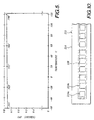
- target 222 illustrated in FIGURE 10 is substituted for target 22.
- Target 222 is similar to target 22 except that it has an elongated configuration and a plurality of magnets 224 (i.e., 224a, 224b, etc.) with the same polarity are used in place of magnet 24.
- a single elongate magnet (not shown) may be used in place of magnets 224.
- base plate 228 is made from a high permeability material and has an elongate configuration.
- Container 234 is made from a nonmagnetic metal and is sized to receive elongate base plate 228 and the array of magnets 224 positioned thereon.
- An elongate version of cover 36 (not shown) is provided for engaging container 234 so as to enclose a space in which magnets 224 and base plate 228 are positioned and protected.
- target 222 is attached to a first object and sensor 50 is attached to a second object designed to move back and forth along an axis extending parallel to the long axis of target 222 such that sensor 50 will be intercepted by the magnetic fields provided by magnets 224, a point will be reached during the movement of the second object where magnet 224 enters the actuation zone of sensor 50.
- This event causes core 52 to saturate to the predetermined value, thereby causing the inductance of inductive element 60 to drop which in turn indicates the second object is within predetermined proximity of the first object.
- sensor 50 will pass out of the magnetic field of magnet 224a and into the magnetic field of magnet 224b.
- the magnets 224 in target 222 are positioned sufficiently close to one another such that core 52 of sensor 50 remains saturated to the predetermined value as the sensor passes between adjacent magnets.
- the inductance of inductive element 60 remains low, thereby indicating the relative proximity of the first and second objects.
- Targets 22 and 222 have been described as including a housing made from a nonmagnetic metal. It is to be appreciated that when sensor assembly 20 (container 34 and cover 36) is designed to be used in an environment where stray currents from external sources will not be present, e.g., in an outer space environment, the housing is not required. In this case, base plate 28 or 228 may be attached directly to a first object.
- the sensor 50 includes a nonmagnetic bobbin 53 upon which is wound the inductive element 60.
- the core 52 extends within the bobbin 53.
- the sensor can operate in either a slide-by mode or a head-on mode. In the slide-by mode, the sensor moves in the Y direction relative to the magnet 24. As the sensor approaches the magnet 24, the magnetic flux lines 46 produced by the magnet 24 enter the core 52. When the flux density reaches a predetermined level in the core, the core saturates causing a corresponding drop in the inductance of the inductive element 60. This change in inductance can be measured by an appropriate electronic circuit to determine when the sensor is within a predefined proximity of the magnet 24.
- the sensor can also be used in a head-on mode, in which the sensor moves in the X direction towards the magnet 24.
- the core 52 saturates, causing a drop in the inductance of the inductive element 60 as described above.
- FIGURE 11 Also shown in FIGURE 11 is an addition to the core element 52.
- the addition is a flux director 120 that comprises a pair of metal strips that are spot welded to or integrally formed at an end of the core.
- the flux director acts to intercept the fringing flux lines 46 from the magnet 24 and direct the flux lines into the core 52.
- the addition of the flux director to the sensor core 52 makes the sensor more sensitive and more accurate.
- FIGURE 12 An enlarged view of the flux director 120 is shown in FIGURE 12.
- the metal strips form four radially extending arms 120a, 120b, 120c and 120d. Each of the arms is spaced at approximately 90° intervals around the core.
- the flux director 120 is made from the same highly permeable material as the core 52.
- the core 52 and flux director 120 are both made of HyMu "80"®.
- the flux director 120 acts to intercept and direct the flux lines from the magnet element 24, shown in FIGURE 11, into the core 52. As a result, the core will saturate at a greater distance away from the magnet than is possible without the flux director.
- the cross-sectional area of the arms that comprise the flux director 120 determines how the sensor will respond when used in a slide-by or head-on mode.
- two arms located on one side of the sensor nearest the target for example, arm 120a and arm 120d, will extend into the fringing magnetic flux lines before the arms located on the other side of the sensor.
- the arms that extend into the flux lines of the magnet will direct the flux lines through the core 52.
- each of the flux director arms have a cross-sectional area that is roughly equal to one-half to one-quarter of the cross-sectional area of the core. Therefore, the total cross-sectional area of that portion of the flux director that extends into the magnetic field producted by the magnet 24 when the core saturates is approximately equal to the cross-sectional area of the core.
- each of the flux director arms should have a cross-sectional area that is approximately equal to one quarter of the cross-sectional area of the core 52.
- each arm should have a cross-sectional area equal to one third of the cross-sectional area of the core. The embodiment shown is a reasonable compromise and functions well in both a head-on and slide-by application.
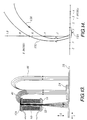
- FIGURE 13 illustrates how the flux director 120 operates to intercept the distant flux lines 46 of the magnet 24 as the sensor 50 slides by.
- the flux lines 40 are drawn into the core 52 by the low reluctance path of the flux director arms.
- the core 52 saturates at a distance that is farther away from the magnet 24 than if the flux director is not used.
- FIGURE 14 is a graph of two curves showing a locus of points at which the sensor has an impedance halfway between its minimum and maximum values.
- a curve 130 shows the mid-value impedance for a sensor without the flux director and a curve 132 shows the mid-value impedance for a sensor with a flux director.
- the curves 130 and 132 show where in relation to the magnet the sensor has a mid-value impedance.
- the X and Y axes are in the same orientation as is shown in FIGURE 11. For example, at the point labeled "A,” the sensor with the flux director added has a mid-value impedance at approximately 0.18 cm (0.07 inches) to the left of the magnet and 0.51 cm (0.2 inches) from the front face of the magnet.
- the sensor without a flux director is also located at 0.51 cm (0.2 inches) in front of the magnet and is approximately 0.10 cm (0.04 inches) to the left of the magnet.
- curve 132 is at the center line with a total slide-by delta of approximately 0.20 cm (0.08 inch)
- curve 130 is at -0.38 cm (-0.15 inch) with a slide-by delta of 0.48 cm (0.19 inches). This is shown by a gap 134 and demonstrates the approximate 2:1 improvement in slide-by accuracy obtained by the use of the flux director.
- FIGURE 15 shows a graph of sensor impedance versus distance for a proximity sensor with and without the flux director when the sensor is used in a head-on mode.
- a line 136 shows the change in impedance versus the head-on distance away from the magnet for a sensor without the flux director.
- a line 138 shows the change in impedance versus distance away from the magnet for a sensor having the flux director.
- the sensor without the flux director reaches its mid-value impedance at a distance of 2.28 cm (0.9 inches) away from the magnet as is indicated by the point "C.”
- the mid-value impedance is reached at a distance of 2.69 cm (1.06 inches) as indicated by the point "D.”
- the flux director provides an 18% improvement in the gap over the sensor with no flux director, thereby making the sensor more sensitive. Also, the flux director increases the range of impedance as the sensor goes from an unsaturated to a saturated state.
- the line 138 has a steeper slope than the line 136 at the point of mid-level impedance as illustrated by points C and D, thereby producing a greater change in impedance for a given change in distance away from the magnet and the transfer function is symmetrical about the mid-value impedance point. Therefore, the sensor that includes the flux director is more accurate for a given change in the X direction than the same sensor without the flux director.
- the use of the flux director 120 on the end of the core 52 improves the sensitivity of the sensor when used in both head-on and slide-by modes.
- the flux director is shown having a generally figure "X" configuration, other configurations may be used depending upon the application in which the sensor is to be used. However, it is important that the flux director and core saturate at roughly the same position away from the magnet and therefore the cross-sectional area of the core needs to be approximately the same as the total cross-sectional area of the flux director at the point where the sensor saturates.
- An important advantage of the present invention as described is that its actuation range-to-weight ratio is about 7 times better than that of conventional variable reluctance proximity sensors. More specifically, proximity sensors having characteristics similar to those of the embodiment of the present invention described above in connection with the discussion of FIGURE 5 and the high temperature stability of sensor assembly 20 can have an actuation range on the order of 1.27 cm (0.5 inches) to at least 5.08 cm (2 inches). By contrast, known variable reluctance proximity sensors of similar weight to such embodiment of the present invention typically have an actuation range on the order of 0.254 cm (0.1 inch). Consequently, the present sensor has particular utility in environments where minimal weight is important, e.g., on aircraft or spacecraft.
- the high actuation range-to-weight ratio of the sensor of the present invention is achieved by the choice of materials used for magnet 24, the provision of plate 28, the choice of materials used for core 52, and the length-to-diameter ratio of sensor 50, all discussed above.
- the sensor assembly of the present invention is its high resistance to electromagnetic fields generated by a source external to the sensor assembly.
- the sensor may be advantageously used in environments subject to large electromagnetic fields, e.g., in aircraft subject to lightning strikes.
- Yet another important advantage of the sensor assembly of the present invention is that its output signal is highly temperature stable. Typically, the output signal of the sensor assembly varies less than about 4% over the temperature range -60°C to +120°C.
Landscapes
- Remote Sensing (AREA)
- Engineering & Computer Science (AREA)
- Life Sciences & Earth Sciences (AREA)
- Physics & Mathematics (AREA)
- Geology (AREA)
- Environmental & Geological Engineering (AREA)
- Electromagnetism (AREA)
- General Life Sciences & Earth Sciences (AREA)
- General Physics & Mathematics (AREA)
- Geophysics (AREA)
- Switches That Are Operated By Magnetic Or Electric Fields (AREA)
- Geophysics And Detection Of Objects (AREA)
- Measurement Of Length, Angles, Or The Like Using Electric Or Magnetic Means (AREA)
Description
- The present invention pertains to magnetic field-dependent proximity sensors and, more particularly, to saturably core magnetic field-dependent proximity sensors.
- Magnetic field-dependent proximity sensors are known, as illustrated in U.S. Patents Nos. 4 719 362 to Nest et. al., 4 587 486 to Soyck, and 4 140 971 to Blincoe. Such proximity sensors typically include a magnet that functions as the target of the sensor, a core made from a material that will magnetically saturate when exposed to a field having a predetermined flux density, and an inductive element, e.g., a coil, surrounding the core. As the magnet is moved toward the core/inductive element assembly, a distance is reached where the magnetic field of the magnet finds the core to be the smallest reluctance path. As a result, the flux of the field enters the core and, as the distance is decreased, eventually saturates the core. This causes the inductance of the inductive element to decrease. By measuring changes in inductance of the inductive element, the presence of the magnetic field, and hence the position of the magnet, may be detected. German Patent No. 3 346 340 which forms the pre-characterising portion of
claim 1 is a similar proximity sensor design. A magnetic core is surrounded by a protective housing that sits on a yoke. When a target magnet is brought close to the core, the yoke saturates. - Magnetic field-dependent proximity sensors are used in a wide range of applications for detecting when a first movement member is positioned in predetermined spaced relationship to a second member. For instance, such proximity sensors may be used to detect the position of devices used to actuate the flap panels in the wings of an aircraft, as disclosed in U.S. Patent No. 4 256 277 to Embree. Although magnetic field-dependent proximity sensors used in aircraft typically function satisfactorily, their performance can be adversely affected when the aircraft is struck by lightning. More specifically, when lightning strikes an aircraft, peak current in excess of 200 Kamps can travel along the skin of the aircraft. These currents generate high frequency electromagnetic fields which may intercept the core and inductor, or the magnet of the target, of a magnetic field-dependent proximity sensor mounted to the aircraft. In some cases, the strength of such fields is sufficient to cause the core to saturate. As a result of this saturation, the inductance of the inductor may fall into a range indicating the magnet, and hence the mechanical element attached thereto, has been moved to within a predetermined proximity of the core and inductive element assembly. Similar change in the detection range of the proximity sensor can occur if the electromagnetic fields demagnetize the magnet of the target. Such erroneous signal information from the proximity sensor can be particularly troublesome when the sensor is used to detect the presence or absence of a mechanical element affecting the safe operation of the aircraft.
- In addition to the sensitivity of known proximity sensors to high frequency electromagnetic fields generated by lightning strikes, known sensors also have a tendency to provide spurious results when the sensor is subjected to electromagnetic interference ("EMI") generated by equipment such as electrical motors, wiring and the like positioned near the proximity sensor. Relatedly, known magnetic field-dependent proximity sensors are not typically designed to detect only that portion of a magnetic field having a predetermined direction component. That is, known magnetic field-dependent proximity sensors are not generally designed to detect the X component of a magnetic field having X, Y and Z directional components, while at the same time substantially not detecting the Y and Z components of the magnetic field. As a consequence of EMI and the inability of known proximity sensors to discriminate as to the directional component of a field it detects, the resolution and/or target distance to field strength ratio of such sensors may not be as good as is desired.
- The actuation zone of known variable reluctance proximity sensors, i.e., the physical region in which the target material must be positioned to be detected by the sensor, is often undesirably small. As a consequence, the respective placement of the target and sensor on the two mechanical elements, the proximity of which is to be detected, is critical to obtain proper proximity detection information. If the sensor and target are positioned too close to one another due to improper installation, mechanical wear, tolerance buildup or other factors, the first mechanical element could contact the second mechanical element during normal operation before the presence thereof is detected. Alternatively, if the sensor and target are positioned too far part due to the above-noted factors, the sensor will never indicate the first mechanical element is within a predetermined proximity of the second element. Such criticality in the relative placement of the sensor and magnet can add significantly to the cost of installing and maintaining the proximity sensor, and can potentially compromise the safe operation of the machine in which the proximity sensor is installed.
- Another problem with known magnetic field-dependent proximity sensors is that accurate proximity information is obtained from such devices only in a relatively narrow temperature range. Because such proximity sensors are frequently used in an environment subjected to significant swings in temperature, e.g., in unheated portions of an aircraft, a strong need exists for a magnetic field-dependent proximity sensor that is highly temperature stable.
- The weight to detection range ratio of known magnetic field-dependent proximity sensors is typically less than is desired. For instance, a known variable reluctance proximity sensor that is representative of the state of the art with respect to weight to detection range ratios weighs 00.59Kg (13 pounds) and has a detection range of 0.254cm (0.1 inch), providing a weight-to-range ratio of 4.305cm/Kg (0.769 inch/pound). This relatively low weight-to-range ratio is especially problematic when the proximity sensor is designed to be used in spacecraft or other equipment where weight is critical.
- According to our invention, there is provided a saturable core proximity sensor of the type that includes a target magnet and an inductor having an inductance that varies when the sensor is positioned near the target magnet, comprising:
- a magnetic target that includes a magnet having a front face and a back face that produces a magnetic field in front of, in back of, and to the sides of the magnet; and
- sensor means for detecting said magnetic field and for indicating when said sensor means is positioned within a predetermined proximity of said magnetic target, said sensor means including a core and an inductive element wherein said core and the inductive element have an inductance that decreases when said core is saturated by the magnetic field produced by the magnet and an inductance that increases when said core is not saturated by the magnetic field produced by the magnet, said change in inductance providing an indication of the proximity of the sensor means to the magnetic target;
- the magnetic target also includes a plate positioned adjacent the magnet for reducing the magnetic field in the back of and at the side of the magnet and for increasing the distance at which the magnetic field extends in a direction perpendicular to the front face of the magnet;
- the core has a distal end and a proximal end and a longitudinal axis that is aligned substantially perpendicular to the front face of the magnet, wherein said core has a cross-sectional area in a plane perpendicular to the longitudinal axis that is substantially smaller than a cross-sectional area of the core along the longitudinal axis, said core becoming magnetically saturated when exposed to magnetic fields of a predetermined flux density that extend along the longitudinal axis of the core, but not saturating when exposed to magnetic fields of the predetermined flux density that extend in a direction substantially deviating from the longitudinal axis of the core; and
- the inductive element surrounding said core produces a second magnetic field that flows through the core and through an air gap that exists between the distal and proximal ends of the core.
- The present invention therefore comprises a saturable core proximity sensor comprising a sensor assembly and a target assembly. The sensor assembly includes a core made from a permeable material that will saturate when exposed to a magnetic field having a predetermined flux density. The inductance of the inductor is less than a predetermined value when the core is saturated and is greater than the predetermined value when the core is not saturated. At the distal end of the sensor core are a set of radially extending flux director arms. Each arm has a cross-sectional area that is approximately one-quarter of the cross-sectional area of the core. The flux director arms are made of the same high permeability material as the core so the flux director arms saturate at the same time as the core. The flux director arms increase the sensitivity of the sensor, as well as increase the rate of change of inductance as the sensor approaches a target assembly.
- The target assembly comprises a base plate made from a material having a high relative permeability and flux saturation value. A high field strength magnet, e.g., a magnet made from samarium cobalt, is positioned on the high permeability plate. The magnet has a planar configuration and is magnetized so that the magnetic field thereof is centered about an axis extending perpendicular to the major plane of the magnet. The high permeability plate reduces the reluctance path surrounding the magnet by about 50%, thereby substantially eliminating that portion of the magnet's field extending in one direction away from the major plane of the magnet and increasing the field strength of that portion of the magnetic field extending in an opposite direction away from the major plane. A nonmagnetic metal housing surrounds and encloses the base and magnet. The housing is designed to function as a Faraday cage, i.e., it cancels electromagnetic fields generated by currents provided by a source external to the proximity sensor so that the electromagnetic fields substantially do not intercept the magnet of the target assembly.
- As the target assembly is moved toward the sensor assembly, a point is reached where the magnetic field of the inductor (generated by the drive current of the sensor assembly) together with the magnetic field of the target assembly cause the core of the sensor assembly to saturate to a level such that the inductance of the inductor decreases to a predetermined value. This predetermined value indicates that the target assembly has been moved to within a predetermined proximity of the sensor assembly.
- Due to its design and construction, the proximity sensor of the present invention is highly temperature stable. In one embodiment of the present invention, the distance between the sensor assembly and target assembly at which the sensor assembly first detected the presence of the target assembly differed less than about 4% over the temperature range of -60°C to +120°C.
- In addition to being highly temperature stable, the present invention has a weight to detection range ratio that is about five times better than that of known variable reluctance proximity sensors. As a consequence, the sensor is highly suitable for use in applications where weight is critical, e.g., in spacecraft.
- The foregoing aspects and many of the attendant advantages of this invention will become more readily appreciated as the same becomes better understood by reference to the following detailed description, when taken in conjunction with the accompanying drawings, wherein:
- FIGURE 1 is a side elevation view of the proximity sensor of the present invention, with the sensor and target being positioned for operation in the slide-by mode;
- FIGURE 2 is an exploded perspective view of the target of the proximity sensor;
- FIGURE 3 is similar to FIGURE 1, except that the sensor and target are positioned for operation in the head-on mode;
- FIGURE 4 graphically illustrates the manner in which the inductance of the inductor of the sensor changes with changes in distance between the sensor and target within a predetermined range for one embodiment of the sensor of the present invention;
- FIGURE 5 illustrates graphically, for one embodiment of the present invention, over a given temperature range, the distance between the sensor and target at which the sensor detects the target;
- FIGURE 6 is a side elevation view of the target, illustrating the manner in which electromagnetic fields from an external current source intercept the target;
- FIGURE 7 is similar to FIGURE 6, except that it illustrates the manner in which the housing of the target cancels such electromagnetic fields;
- FIGURE 8 is similar to FIGURE 3, except that the target has been moved closer to the sensor, and the magnetic fields of the inductor of the sensor are illustrated;
- FIGURE 9 is a circuit diagram of one embodiment of the proximity sensor;
- FIGURE 10 is a top view of another embodiment of the target of the proximity sensor;
- FIGURE 11 is an exploded three-dimensional view of the proximity sensor according to the present invention, including a flux director according to another aspect of the present invention;
- FIGURE 12 is a side elevational view of a sensor core including the flux;
- FIGURE 13 is a cross-sectional view of the proximity sensor showing how the fringing flux lines from the target magnet are drawn into the sensor core by the flux director;
- FIGURE 14 is a graph showing the improved sensitivity obtained using the flux director when the proximity sensor is operated in a slide-by mode; and
- FIGURE 15 is a graph showing the improved sensitivity obtained using the flux director when the proximity sensor is used in a head-on mode.
- Referring to FIGURE 1, the present invention is a saturable core
proximity sensor assembly 20 comprising atarget 22 and asensor 50. Typically, either target 22 orsensor 50 is attached to a first object (not shown) that is mounted so as to be movable along a predefined path relative to a second object (not shown) to which the other of thetarget 22 orsensor 50 is attached. In some cases, the second object will also be mounted so as to move along a predetermined path. Depending upon the configuration employed,sensor assembly 20 may be used to detect the presence of the first object relative to the second object, or may be used to determine the distance between the first object and the second object within a given range, as discussed in greater detail hereinafter. - Referring to FIGURE 2,
target 22 comprises amagnet 24. Ideally,magnet 24 has the highest Br (residual flux density) and Hc (coercive force) values possible, which values will not degrade with the changes in temperature to be encountered bysensor assembly 20. Higher Br values provide a longer actuation range forsensor assembly 20, and higher Hc values provide increased protection from demagnetizing fields. Both Br and Hc determine the energy in the magnet. Unfortunately, commercially available magnets having sufficiently high Br and Hc values and high stability of such values over a wide temperature range (e.g., -60°C to +120°C) are not believed to exist. Consequently, either high Br and Hc values or high temperature stability must be sacrificed. - When high temperature stability of Br and Hc values is desired, one family of magnetic materials that may be satisfactorily used for
magnet 24 is composed of rare earth elements and cobalt, e.g., samarium cobalt. Preferably,magnet 24 made from such materials has a Br of at least about 8,000 Gauss, an Hc (coercive force) of at least about 7,000 Oersteds, a reversible temperature coefficient of induction of about -0.09% per °C in therange 25°C to 100°C, and a Curie temperature of at least about 250°C. Ugimag Company distributes this type of magnet under the mark RECOMA®. - Depending upon the intended application of
sensor assembly 20, the specific values for the foregoing characteristics ofmagnet 24 may differ somewhat from those values indicated above. For instance, when the sensor assembly is intended to be used in an environment subject to temperature swings of only about -55°C to 70°C the Curie temperature ofmagnet 24 may be lower, thereby permitting neodymium iron boron magnets to be used asmagnet 24. An advantage of such magnets is their relatively high Br values (i.e., 11,000 Gauss), which would result in an increase in operating range for the sensor. Ugimag Company distributes this type of magnet under the mark REFEMA®. -
Magnet 24 is magnetized so that its magnetic field extends in opposite directions through the thickness dimension and is centered, i.e., has a maximum X directed flux density on the centroid of the magnet. Additionally, the magnetic field distribution Bx at a point X on the magnet central line (the axis intersecting the center of the magnet and extending perpendicular to the major plane of the magnet) varies based on the physical configuration of the magnet in accordance with the following formulas:
Cylindrical configuration:
- Br =
- residual flux density of magnet
- L =
- length of magnet
- R =
- radius of magnet
- X =
- distance from surface of magnet along magnet central line (measured along axis extending coaxial with longitudinal axis of cylinder)
- Br =
- residual flux density of magnet
- A =
- length of magnet
- B =
- width of magnet
- L =
- thickness of magnet (dimension parallel to magnet central line)
- X =
- distance from surface of magnet along magnet central line
- Thus, as indicted by the foregoing equations, the size and configuration of
magnet 24 is selected based on the distance betweentarget 22 andsensor 50 at which the presence of the target is to be detected. -
Target 22 further comprises abase plate 28 made from a material preferably having a relative permeability of at least about 100, i.e., 100 times the permeability of a vacuum. In addition,base plate 28 preferably has a flux saturation value of at least about 14,000 Gauss. Magnetic alloys similar to type 416 stainless steel may be used in the construction ofbase plate 28. Preferably, the cross-sectional area oftop surface 29 ofbase plate 28 is greater than the cross-sectional surface area oftop surface 25 ofmagnet 24. In one embodiment of the present invention,surface 25 ofmagnet 24 measures 1.27 cm x 1.27 cm (0.5 inch x 0.5 inch) andsurface 29 ofbase plate 28 measures 2.54 cm x 2.54 cm (1.0 inch x 1.0 inch), withmagnet 24 having a thickness of 0.318 cm (0.125 inch) andplate 28 having a thickness of 0.102 cm (0.04 inch). - The relative permeability, flux saturation level and thickness values for
base plate 28 are relative, to some extent. Materials with lower saturation levels may be used if thickness and/or permeability values are increased. Also, the relative permeability, flux saturation and thickness values ofbase plate 28 may have to be adjusted somewhat depending on the magnitude of the Br value formagnet 24. Such balancing of parameters will be governed by the intended use ofsensor 20, and is believed to be well within the abilities of one of ordinary skill in the art. -
Target 22 also comprises a two-part housing consisting ofcontainer 34 andcover 36.Container 34 includes four sides and a base and is open on top. The container is sized to receivemagnet 24 andbase plate 28.Cover 36 is designed to fit overcontainer 34 so as to close off the open end of the container. - To assemble
target 22,base plate 28 is secured to the bottom ofcontainer 34 by suitable means, e.g., using an adhesive.Magnet 24 is then polarized as desired and positioned on plate 28 (centered in this example). Adhesive is used to bond the magnet into position as illustrated in FIGURE 6. Aftercover 36 is so positioned, the cover is welded or otherwise secured tocontainer 34 such that electrical continuity is assured.Container 34 and cover 36 are sized so thatmagnet 24 andbase plate 28 are protected without stress. Attachment means such as threadedstuds 37, may be mounted tocontainer 34 for use in securing target to an object, the proximity of which, relative to a second object, is to be determined. - Referring to FIGURES 1 and 2,
target 22 generates a magnetic field that may be represented by concentric flux lines 46 (FIGURE 1). The flux lines 46 emanate outwardly away frommagnet 24 and then curve around and enter thebase plate 28 along the least reluctance path. The flux is then carried along the base plate until it reentersmagnet 24. The flux density of the magnetic field provided bytarget 22 in the direction extending parallel toaxis 48 is greatest adjacent to the central axis, the latter extending perpendicular to the top surface of the target and intersecting the center of themagnet 24. - Ordinarily, the flux lines associated with the magnetic field of a magnet emanate outwardly and loop around the magnet and then reenter the magnet at a position opposite where the flux lines exited the magnet, as indicated by flux line 47 (FIGURE 1). However, due to the high relative permeability of
base plate 28, the latter provides a lower reluctance path than the region adjacent the back side oftarget 22, i.e., the area inspace surrounding studs 37. In this regard, the permeability and geometry ofbase plate 28 should be selected so that the latter reduces at least 90% of the reluctance path on the back side oftarget 22. By appropriate sizing and selection of materials formagnet 24 andbase plate 28, a reasonable goal is to reduce approximately 95-98% of the reluctance path on the back side oftarget 22. Thus,base plate 28 effectively prevents the emanation of a magnetic field from the back side oftarget 22. - In addition to preventing such emanation of the magnetic field,
base plate 28 increases the strength of the magnetic field extending away from the front side ofsensor assembly 20. Specifically, the magnetic field extends about 1.6 times as far away from the front surface oftarget 22, as measured alongcentral axis 48, as it would without the presence ofbase plate 28. - Referring again to FIGURE 1,
sensor 50 comprises a core 52 made from a magnetically saturable material having a high relative permeability. When high temperature stability ofsensor 20 is desired,core 52 should have the highest relative permeability possible. However, a relative permeability exceeding 20,000 has been found to be satisfactory. Lower permeability material, i.e., material having a relative permeability less than 20,000, may also be satisfactorily employed when some loss in temperature stability over a wide range can be accommodated.Core 52 may have a circular or rectangular cross-sectional configuration, as desired. The long dimension ofcore 52, i.e., the dimension extending alongcentral axis 54, is significantly greater than the cross-sectional width or diameter of the core. The specific length and size ofcore 52 will vary depending upon the environment in whichsensor assembly 20 is to be used. However, to optimize the temperature stability ofsensor assembly 20 and minimize the measurement of side fields, core 52 preferably has a relatively small cross-sectional area, e.g., 0.0097 cm2 (0.0015 square inch), and a length-to-width ratio of at least 7 to 1. In one embodiment of the invention,core 52 had a width of 0.238 cm (0.094 inch), a thickness of 0.0356 cm (0.014 inch), and a length of 1.90 cm (0.75 inch).Core 52 has afront end 56. -
Sensor 50 also includes aninductive element 60 surroundingcore 52.Inductive element 60 comprises a plurality of turns of relatively fine gauge wire, e.g., # 37 copper wire, the ends of which are coupled with a circuit (not shown) for receiving the output ofsensor assembly 20. As also discussed in greater detail hereinafter, the length ofinductive element 60 will vary as a function of the environment and intended mode of operation ofsensor assembly 20. -
Inductive element 60 is coupled with the circuit (not shown) with whichsensor assembly 20 is connected. The circuit provides an AC drive current toinductive element 60 that causes the element to produce a magnetic field identified by flux lines 62 (FIGURES 1 and 3). These flux lines travel throughcore 52, exit one end of the core, travel around the outside ofsensor 50 and reenter the other end of the core. The strength of the magnetic field associated withinductive element 60 will vary as a function of the amplitude of the drive current. In turn, the strength of the magnetic field ofinductive element 60 will be affected whencore 52 reaches saturation which determines the detection range ofsensor assembly 20, as discussed in greater detail hereinafter. Thus, the specific characteristics of the drive current forsensor 50 are a design choice to be made by one of ordinary skill in the art based on the desired application and actuation range forsensor assembly 20. However, the AC drive current provided tosensor 50 will typically be on the order of 1-3 milliamps at 1 volt with a frequency in the range of 1000 to 3000 Hz. In any event, the drive current forinductive element 60 is insufficient to cause the element to generate a magnetic field of a strength sufficient to causecore 52 to saturate to the predeterminedlevel indicating target 22 is positioned within a predetermined proximity ofsensor 50, as discussed in greater detail hereinafter. -
Sensor 50 preferably comprises a protective housing (not shown) surroundingcore 52 andinductive element 60. This housing is made from a nonmagnetic material, such as an appropriate type of stainless steel and may be hermetic. -
Sensor assembly 20 is designed to be operated in either the slide-by mode, as illustrated in FIGURE 1, or the head-on mode, as indicated in FIGURE 3. In the slide-by mode,target 22 is mounted to a first object (not shown) positioned adjacent a second object (not shown) to whichsensor 50 is mounted. Relative movement occurs between the first and second objects along an axis or axes extending parallel to axis 70 (FIGURE 1). Depending upon the environment in whichproximity sensor 20 is designed to be used, the first object may be fixed and the second object designed to move parallel toaxis 70. In other cases, the second object may be fixed and the first object designed to move parallel toaxis 70. In a third case, both first and second objects are designed to move back and forth along axes extending parallel toaxis 70. - As
target 22 moves towardsensor 50, a point is reached where flux lines 46 begin to entercore 52 and follow it as the least reluctance path. As discussed in greater detail hereinafter, the physical dimensions and saturation value ofcore 52, together with the dimensions and configuration ofinductive element 60, and the characteristics of the drive current provided toelement 60, will determine when, after this point, the core reaches magnetic saturation. Whenever at least a portion oftarget 22 is positioned in the ball-shaped actuation zone 72 (FIGURE 1), the magnetic field generated bytarget 52 together with the magnetic field provided byinductive element 60 will saturate the core to a predetermined value. More specifically,core 52 will saturate to a predetermined value when at least a portion oftarget 22 crosses over theactuation zone boundary 72a and will unsaturate such that its saturation value is less than the predetermined value when all oftarget 22 crosses over deactuation zone boundary 72b. The spacing betweenboundaries 72a and 72b is relatively small, i.e., less than about 0.05 cm (0.020 inch).Actuation zone boundaries 72a and 72b are caused by hysteresis in the electronics (not shown) to whichsensor assembly 20 is connected, such electronics not forming part of the present invention, and not by differences in the magnitude of the predetermined saturation value whentarget assembly 22 is moved towardsensor 50 versus when the target assembly is moved away fromsensor 50. - Referring to FIGURES 3 and 4, when
core 52 saturates to the predetermined value, the inductance ofinductive element 60 drops rapidly from a relatively high value representing virtually no saturation of the core to a relatively low value representing virtually complete saturation of the core. The "no saturation" inductance level is represented by the upper horizontal portion ofinductance curve 80 in FIGURE 4, and the "complete saturation" inductance level is represented by the lower horizontal portions ofcurve 80. With the present invention, the magnitude of the inductance ofelement 60 whencore 52 is not saturated is typically about 6-8 times the magnitude of the inductance ofelement 60 whencore 52 is saturated. - As the inductance of
inductive element 60 drops from the upper "no saturation" level to the lower "complete saturation" level, the inductance passes through a predetermined level identified by an "X" oncurve 80 in FIGURE 4. This predetermined inductance level indicates either (a) that target 22 has moved within a predetermined proximity ofsensor 50, when the inductance ofinductive element 60 decreases through the predetermined inductance level, or (b) that target 22 has moved outside of a predetermined proximity ofsensor 50, when the inductance ofinductive element 60 increases through the predetermined inductance level. The specific magnitude of the predetermined inductance value will differ depending upon the size ofinductive element 60 and the position on the slope of the inductance curve selected as the predetermined inductance value. Preferably, the predetermined inductance value is about 50% of the "no saturation" inductance level to provide equal margins for "near" and "far" and a symmetrical transfer function, as illustrated in FIGURE 4. Whentarget 22 is positioned within a predetermined proximity ofsensor 50, it is also known that the first object to which the target is attached is positioned in predetermined proximity to the second object to which the sensor is attached, as measured alongaxis 70. - The rate at which the inductance of
inductive element 60 drops from the upper value representing nonsaturation ofcore 52 to the lower value representing saturation ofcore 52, relative to changes in distance betweentarget 22 andsensor 50, will vary depending upon the size, configuration and permeability ofcore 52 and the size, configuration and drive current ofinductive element 60. Typically, whensensor 20 is operated in the slide-by mode, it is desired that the inductance versus distance curve have a very steep function between saturation and nonsaturation points, e.g., as illustrated byinductance curve 80. To this end,sensor 20 is designed so that its entire length will rapidly saturate when exposed to a magnetic field having a predetermined flux density. That is,core 52 is relatively short (e.g.,core 52 has a length to diameter ratio in the range 5 to 1 - 10 to 1) and has a high relative permeability (e.g., 20,000) with the length ofinductive element 60 being about equal to that ofcore 52. With this configuration,sensor assembly 20 will function as an "on/off" proximity detector. - For certain slide-by application, it may be desirable to flatten out somewhat the inductance versus distance curve for
sensor 50 so that the specific inductance ofinductive element 60 may be equated with the spacing betweentarget 22 andsensor 50. For instance, whensensor assembly 20 is attached to two movable objects, the spacing between which may vary over time, the change in spacing between the objects from a baseline distance may be determined by monitoring the absolute value of the inductance ofinductive element 60. To achieve this flattening of the inductance versus distance curve, the length ofcore 52 andinductive element 60 are increased somewhat. -
Actuation zone 72 extends outwardly fromfront end 56 along axis 54 a relatively large distance, as compared to known magnetic-field-dependent variable reluctance proximity sensors. As a result of this configuration, whensensor assembly 20 is used in the slide-by mode, relatively wide latitude exists in the placement oftarget 22 on the first object andsensor 50 on the second object, as measured along axes extending parallel tocentral axis 54. That is, the spacing betweentarget 22 andsensor 50, as measured along an axis extending parallel tocentral axis 54, may vary a relatively large amount, e.g., 1.27 cm (0.5 inch) in one embodiment of the present invention, while still ensuringtarget 22 will fall withinactuation zone 72 when positioned adjacent to thefront end 56 ofsensor 50. On the other hand, known variable reluctance proximity sensors used in the slide-by mode typically can accommodate only a relatively small, e.g., ±0.127cm (±0.05 inch), variation in spacing between target and sensor. -
Sensor assembly 20 is also designed to be operated in the head-on mode, as indicated in FIGURE 3. In this mode of operation, the first object to which thetarget 22 is attached and the second object to which thesensor 50 is attached are designed to move toward and away from one another such thatcentral axis 48 of the target extends parallel to or coaxial withcentral axis 54 of the sensor, i.e., one or both of the first and second objects move along an axis or axes extending parallel toaxis 80 in FIGURE 3. - When
sensor assembly 20 is set up to be operated in the head-on mode, the sensor assembly may be used to either detect when the first object to whichtarget 22 is attached is within a predetermined proximity of the second object to whichsensor 50 is attached or to detect the distance between the first and second objects, when such distance falls within a predetermined range. - Referring to FIGURES 3 and 4, when
sensor assembly 20 is operated in the head-on mode for detecting when a first object is within a predetermined proximity of the second object, thecore 52 andinductive element 60 ofsensor 50 are preferably relatively short, i.e., the length ofcore 52 is on the order of 5 to 10 times the width or diameter of the core, with the length ofinductive element 60 being similar to the length ofcore 52. As discussed above in connection with the description of the operation ofsensor assembly 20 in the slide-by mode, a ball-shapedactuation zone 72 extends outwardly from thefront end 56 of the sensor. Thus, as the first object to which thetarget 22 is attached moves toward the second object to which thesensor 50 is attached, target 22 passes withinactuation zone 72, thereby causing the core of the sensor to begin saturating and the inductance of the inductive element to begin decreasing. Whensensor 50 is relatively short, the core will change from an unsaturated to a saturated state, and the inductance ofinductive element 60 will change from a relatively high value to a relatively low value, as a result of only a relatively small amount of relative movement between the target and sensor, as illustrated bygraph 80 in FIGURE 4. As discussed above, whensensor 50 is relatively short, it functions substantially as an on-off proximity detector. Because the inductance versus distance curve for a relativelyshort sensor 50 has a very steep function in the transition region between saturation and nonsaturation,sensor assembly 20 has a very good signal-to-noise ratio and a high immunity to EMI (electromagnetic interference). - Due to the relatively low reversible temperature coefficient of induction of magnet 24 (e.g., about -0.09%/°C in the
range 25°C to 100°C), the relatively large air gap associated withsensor 50, and the relatively small cross section ofcore 52,sensor assembly 20 is highly temperature stable. This characteristic of the present invention is highly advantageous when consistent proximity or distance detection information is required over a relatively wide temperature range (e.g., -60°C to 150°C). - The high temperature stability of
sensor assembly 20 is illustrated by the graph set forth in FIGURE 5. In one embodiment ofsensor assembly 20, when operated in the head-on mode, the position at which thesensor 50 first detects the presence oftarget 22 differs less than 4% over the temperature range from about -60°C to about 120°C. In this embodiment,sensor 50 consists of a core 52 having a cross section area of 0.0084 cm2 (0.0013 square inch), a length of about 1.90 cm (0.75 inch), and a relative permeability of about 20,000.Inductive element 60 consists of turns of copper wire wrapped around substantially the entire length of the core to a thickness such that the outside diameter of the inductive element is about 1.27 cm (0.5 inch). The core and inductive element are encased in a cylindrical housing made from a nonmagnetic stainless steel and having a wall thickness of about 0.05 cm (0.02 inch). Also in this embodiment ofsensor assembly 20,magnet 24 measures about 1.27 cm x 1.27 cm x 0.317 cm (0.5 inch x 0.5 inch x 0.125 inch), is made from samarium cobalt, has a residual induction Br of about 10,000 Gauss, a coercive force Hc of about 10,000 Oersteds, a reversible temperature coefficient of induction of about -0.09%/°C (25°C to 100°C), and a Curie temperature of about 312°C. Base plate 28 measures about 2.54 cm x 2.54 cm x 0.127 cm (1 inch x 1 inch x 0.05 inch) and is made from a stainless alloy having a relative permeability of about 100 and a saturation value of about 14,000 Gauss.Container 34 and cover 36 are made from aluminum plate having a thickness of about 0.076 cm (0.03 inch). - The inductance of the
inductive element 60 of the embodiment ofsensor assembly 20 described in the preceding paragraph also changes less than about 4% over the temperature range -60°C to 120°C whentarget 22 is positioned in fixed relation tosensor 50 such thatcore 52 of the sensor is saturated by the magnetic field generated bytarget 22. For instance, with the embodiment ofsensor assembly 20 described in the preceding paragraph, at 30°Cinductive element 60 had an inductance of about 4 mh at 2 KHz drive signal, such inductance varying less than about 2% over the temperature range -60°C to 120°C for a total change of less than about 4%. Because the inductance ofinductive element 60 constitutes the output signal ofsensor assembly 20, such relatively minor changes in inductance demonstrate that highly consistent results may be obtained fromsensor assembly 20 over a relatively wide temperature range. - The above-described embodiment of
sensor assembly 20 has a detection distance-to-weight ratio of about 7 to 1. That is,sensor 50 will first detect the presence oftarget 22, whensensor assembly 20 is operated in the head-on mode, whentarget 22 is moved to within about 1.9 cm (0.75 inch) ofsensor 50, with theentire sensor assembly 20 weighing about 0.1 pounds. Similar detection distance-to-weight ratios are obtained when the above-described embodiment ofsensor assembly 20 is operated in the slide-by mode. By selecting amagnet 24 that is larger than that used in the embodiment ofsensor assembly 20 described above, or by using amagnet 24 having a residual induction, Br, greater than 10,000 Gauss, detection distance-to-weight ratios significantly in excess of 10 to 1 may be achieved with the present invention. -
Sensor assembly 20 is designed to provide consistent, repeatable proximity or distance detection information even in the presence of relatively strong electromagnetic fields generated by current from a source external to the sensor assembly. For instance, whensensor assembly 20 is installed in an aircraft, the latter may be subjected to lightning strikes having a peak current of 200 Kamps or more. This current, which sheets along the outer skin of the aircraft, generates electromagnetic fields having an intensity of 10,000 amps/M or more, which fields may interceptsensor assembly 20 when positioned adjacent the outer skin of the aircraft. Such fields could temporarily adversely affect the operation ofsensor assembly 20 by saturatingcore 52 ofsensor 50, thereby causing the inductance ofinductive element 60 to decrease to a level indicative oftarget 22 being positioned within a predetermined proximity ofsensor 50. Additionally, electromagnetic fields associated with a lightning strike or other large current source could permanently affect the operation ofproximity sensor 20 by demagnetizingmagnet 24 oftarget 22. - To avoid such temporary or permanent effects of lightning strikes or other external sources of current,
housing container 34 and cover 36 are provided. As noted above,container 34 and cover 36 are made from a nonmagnetic metal having a fairly high conductivity, i.e., a conductivity equal to at least half the conductivity of copper. It is preferred that aluminum be used in the construction ofcontainer 34 and cover 36 because it is relatively noncorrosive. However, other materials having a conductivity equal to or greater than that of aluminum, e.g., copper, may also be satisfactorily employed, particularly where corrosion will not occur or can be accommodated. - When
container 34 and cover 36 are assembled as illustrated in FIGURES 1 and 3 so as to retainmagnet 24 andbase plate 28 therein, the container and cover function as a Faraday cage. In this regard, electromagnetic fields generated by current from a source external tosensor assembly 20 which extend so as to intercepttarget 22 assume a pattern represented byflux lines Flux lines 90a extend in a first direction along concentric substantially circular paths centered about a point adjacent one end oftarget 22, andflux lines 90b extend in an opposite direction in concentric substantially circular paths centered about a second point positioned adjacent an opposite end oftarget 22 and overlapping the paths offlux lines 90a. Because theflux lines magnet 24, that portion of the magnetic field represented by the flux lines extending throughmagnet 24 is substantially cancelled, thereby producing a resultant field as represented byflux lines 92 in FIGURE 7. As theseflux lines 92 indicate, at most only the outer edges ofmagnet 24 are intercepted by relatively weak electromagnetic fields. - The effect of a relatively strong lightning strike on the embodiment of
sensor assembly 20 described above in connection with the discussion of FIGURE 5 was investigated. It was assumed that the wave shape of the lightning current was a double decaying exponential with a 200 Kamp peak at 6.4 microseconds and a 50% decay at 69 microseconds. It was assumed also that the proximity sensor was mounted adjacent the outer surface of a wing of an aircraft which was subjected to a lightning strike having the characteristics described above. In view of the manner in whichcontainer 34 andhousing 36 cancel electromagnetic fields generated by a current from an external source, as described above, it was calculated that the intensity, H, of such fields at theupper surface 25 ofmagnet 24 was about 45 Oersteds. By way of contrast, it was calculated that a field having an intensity of 13,500 Oersteds would be required to demagnetizemagnet 24. Thus, the operation ofsensor assembly 20 is virtually unaffected by electromagnetic fields generated by currents from an external source having a magnitude on the order of that which might be encountered in connection with a relatively large magnitude lightning strike. -
Container 34 and cover 36 also provide physical protection formagnet 24 andplate 28. In addition,container 34, with its mountingstuds 37, provides a convenient way of securingtarget 22 to an object. - An important characteristic of
sensor assembly 20, particularly whensensor 50 is relatively long proportionate to its diameter, i.e., a length-to-diameter ratio of more than 5 to 1, is thatsensor assembly 20 substantially will not detect side fields extending transversely tocentral axis 54 ofsensor 50. Such side fields typically consist of electromagnetic interference (EMI) generated by electrical equipment positionedadjacent sensor assembly 20 and by other known factors. - As illustrated in FIGURE 8,
flux lines 46 associated with the magnetic field generated bytarget 22 consist of direction components extending along the X, Y, and Z axes. However, because the long dimension ofcore 52 extends parallel to the X directional components, as defined by the coordinate axis illutrated in FIGURE 8, the core provides a least reluctance path substantially only for the X directional components, and hence only the latter will entercore 52 and cause the latter to saturate. The Y and Z directional components will find the reluctance path provided bycore 52 to be sufficiently high as to substantially prevent the Y and Z components from entering and affecting the saturation of the core. Thus, astarget 22 is moved towardsensor 50, in either the slide-by or head-on mode, a point is reached where the X directional components entercore 52, cause the latter of saturate to the predetermined value (together with the field provided by inductive element 60), and thereby cause the inductance ofinductive element 60 to drop to a level indicating the target is positioned within predetermined proximity of the sensor. In this regard, it is to be appreciated that themagnetic field 62 associated withinductive element 60 consists principally of X directional components, i.e., directional components extending along the length of the core. However, the flux density offield 62 is insufficient to causecore 52 to saturate to the predetermined value. - Thus, side or cross fields generated by EMI or other sources have little, if any, effect on the ability of
sensor 50 to accurately and consistenly detect the proximity or spacing oftarget 22. Additional protection from the effects of EMI and other fields approaching from the back side oftarget 22 is achieved as a consequence of the use ofbase plate 28. As discussed above, as a consequence of the high relative permeability ofbase plate 28, the latter effectively functions as a shield to magnetic fields. - When determining the size and configuration of
sensor 50, consideration needs to be given to the electronic environment in whichsensor assembly 20 is to be used. Because the change in inductance ofinductive element 60 as a consequence ofcore 52 switching between the saturated and unsaturated states can be relatively large, e.g., greater than 6 to 1,sensor 50 should be sized so that the change of inductance falls within a range that can be accommodated by the electronic environment in whichsensor assembly 20 is installed. For instance, in the BITE (built-in test equipment) environment of commercial aircraft, an inductive LRU (line replaceable unit) might have an acceptable range of 4.2 mh to 10 mh, with inductances falling outside of this range being considered a fault in the LRU. Thus, ifsensor assembly 20 is designed so that the inductance ofinductive element 60 has a range of 3 mh to 18 mh, the BITE system would consider the operation ofproximity sensor 20 to be constantly in fault. - Referring to FIGURE 9, to avoid this problem,
sensor 50 is sized and configured so that its inductance varies over a relatively small range, e.g., 0.5 mh to 3 mh. By connectingsensor 50 in series with aninductive element 100 to theelectronic circuit 102 with which the proximity sensor is designed to be used, and by appropriate selection ofinductive element 100, the output of the circuit consisting ofsensor 50 andinductive element 100 may be designed to fall within the prescribed range of the BITE system. For instance, for a BITE system having a prescribed range of 4.2 mh to 10 mh,sensor assembly 20 is designed so that the inductance ofinductive element 60 ranges between 0.5 mh and 3 mh, and the inductance ofinductive element 100 is 4 mh. - In certain slide-by mode applications, it is not sufficient to know when the first object to which
target 22 is attached has passed by a predetermined point on a second object to whichsensor 50 is attached. Such information is provided by the embodiment ofsensor assembly 20 illustrated in FIGURE 1. Instead, under certain circumstances, it is desirable to know if the first object is positioned anywhere along a path on the second object. In other words, under certain applications, a continuous output signal is desired whenever the first object is positioned anywhere along the prescribed path on the second object. - To achieve the above-described slide-by operation, target 222 illustrated in FIGURE 10 is substituted for
target 22.Target 222 is similar to target 22 except that it has an elongated configuration and a plurality of magnets 224 (i.e., 224a, 224b, etc.) with the same polarity are used in place ofmagnet 24. Alternatively, a single elongate magnet (not shown) may be used in place of magnets 224. Thus,base plate 228 is made from a high permeability material and has an elongate configuration.Container 234 is made from a nonmagnetic metal and is sized to receiveelongate base plate 228 and the array of magnets 224 positioned thereon. An elongate version of cover 36 (not shown) is provided for engagingcontainer 234 so as to enclose a space in which magnets 224 andbase plate 228 are positioned and protected. - Assuming
target 222 is attached to a first object andsensor 50 is attached to a second object designed to move back and forth along an axis extending parallel to the long axis oftarget 222 such thatsensor 50 will be intercepted by the magnetic fields provided by magnets 224, a point will be reached during the movement of the second object where magnet 224 enters the actuation zone ofsensor 50. This event causescore 52 to saturate to the predetermined value, thereby causing the inductance ofinductive element 60 to drop which in turn indicates the second object is within predetermined proximity of the first object. As the second object continues to move along the long axis oftarget 222,sensor 50 will pass out of the magnetic field ofmagnet 224a and into the magnetic field ofmagnet 224b. Preferably, the magnets 224 intarget 222 are positioned sufficiently close to one another such thatcore 52 ofsensor 50 remains saturated to the predetermined value as the sensor passes between adjacent magnets. Thus, as long as the second object is positioned relative to the first object such thatcore 52 ofsensor 50 is saturated to the predetermined value by the magnetic field of at least one of the magnets 224target 222, the inductance ofinductive element 60 remains low, thereby indicating the relative proximity of the first and second objects. -
Targets container 34 and cover 36) is designed to be used in an environment where stray currents from external sources will not be present, e.g., in an outer space environment, the housing is not required. In this case,base plate - A variation of the
proximity sensor 50 is shown in FIGURE 11. Thesensor 50 includes anonmagnetic bobbin 53 upon which is wound theinductive element 60. Thecore 52 extends within thebobbin 53. The sensor can operate in either a slide-by mode or a head-on mode. In the slide-by mode, the sensor moves in the Y direction relative to themagnet 24. As the sensor approaches themagnet 24, themagnetic flux lines 46 produced by themagnet 24 enter thecore 52. When the flux density reaches a predetermined level in the core, the core saturates causing a corresponding drop in the inductance of theinductive element 60. This change in inductance can be measured by an appropriate electronic circuit to determine when the sensor is within a predefined proximity of themagnet 24. - The sensor can also be used in a head-on mode, in which the sensor moves in the X direction towards the
magnet 24. When the sensor is close enough, the core 52 saturates, causing a drop in the inductance of theinductive element 60 as described above. - Also shown in FIGURE 11 is an addition to the
core element 52. The addition is aflux director 120 that comprises a pair of metal strips that are spot welded to or integrally formed at an end of the core. The flux director acts to intercept thefringing flux lines 46 from themagnet 24 and direct the flux lines into thecore 52. As will be described in further detail below, the addition of the flux director to thesensor core 52 makes the sensor more sensitive and more accurate. - An enlarged view of the
flux director 120 is shown in FIGURE 12. The metal strips form four radially extendingarms flux director 120 is made from the same highly permeable material as thecore 52. In the preferred embodiment, thecore 52 andflux director 120 are both made of HyMu "80"®. As described above, theflux director 120 acts to intercept and direct the flux lines from themagnet element 24, shown in FIGURE 11, into thecore 52. As a result, the core will saturate at a greater distance away from the magnet than is possible without the flux director. - The cross-sectional area of the arms that comprise the
flux director 120 determines how the sensor will respond when used in a slide-by or head-on mode. In the slide-by mode, two arms located on one side of the sensor nearest the target, for example,arm 120a andarm 120d, will extend into the fringing magnetic flux lines before the arms located on the other side of the sensor. The arms that extend into the flux lines of the magnet will direct the flux lines through thecore 52. In order that the portion of the flux director that extends into the magnetic flux lines andcore 52 saturate at the same time, it is desirable that each of the flux director arms have a cross-sectional area that is roughly equal to one-half to one-quarter of the cross-sectional area of the core. Therefore, the total cross-sectional area of that portion of the flux director that extends into the magnetic field producted by themagnet 24 when the core saturates is approximately equal to the cross-sectional area of the core. - When the sensor is used in a head-on mode, all the flux director arms will be equally exposed to the fringing magnetic field produced by the
magnetic field 24 as the sensor moves toward the magnet. If the flux director is to saturate at the same time as the core, then each of the flux director arms should have a cross-sectional area that is approximately equal to one quarter of the cross-sectional area of thecore 52. As will be appreciated by those skilled the art, if the flux director was made with three arms and used in a head-on mode, then each arm should have a cross-sectional area equal to one third of the cross-sectional area of the core. The embodiment shown is a reasonable compromise and functions well in both a head-on and slide-by application. - FIGURE 13 illustrates how the
flux director 120 operates to intercept thedistant flux lines 46 of themagnet 24 as thesensor 50 slides by. As the sensor nears themagnet 24 from the left, the flux lines 40 are drawn into the core 52 by the low reluctance path of the flux director arms. As a result, the core 52 saturates at a distance that is farther away from themagnet 24 than if the flux director is not used. - FIGURE 14 is a graph of two curves showing a locus of points at which the sensor has an impedance halfway between its minimum and maximum values. A
curve 130 shows the mid-value impedance for a sensor without the flux director and acurve 132 shows the mid-value impedance for a sensor with a flux director. Thecurves curves curve 132 is at the center line with a total slide-by delta of approximately 0.20 cm (0.08 inch), whilecurve 130 is at -0.38 cm (-0.15 inch) with a slide-by delta of 0.48 cm (0.19 inches). This is shown by agap 134 and demonstrates the approximate 2:1 improvement in slide-by accuracy obtained by the use of the flux director. - FIGURE 15 shows a graph of sensor impedance versus distance for a proximity sensor with and without the flux director when the sensor is used in a head-on mode. A
line 136 shows the change in impedance versus the head-on distance away from the magnet for a sensor without the flux director. Similarly, aline 138 shows the change in impedance versus distance away from the magnet for a sensor having the flux director. As can be seen from the graphs, the sensor without the flux director reaches its mid-value impedance at a distance of 2.28 cm (0.9 inches) away from the magnet as is indicated by the point "C." Similarly, for a sensor having the flux director, the mid-value impedance is reached at a distance of 2.69 cm (1.06 inches) as indicated by the point "D." In the head-on mode, the flux director provides an 18% improvement in the gap over the sensor with no flux director, thereby making the sensor more sensitive. Also, the flux director increases the range of impedance as the sensor goes from an unsaturated to a saturated state. Finally, theline 138 has a steeper slope than theline 136 at the point of mid-level impedance as illustrated by points C and D, thereby producing a greater change in impedance for a given change in distance away from the magnet and the transfer function is symmetrical about the mid-value impedance point. Therefore, the sensor that includes the flux director is more accurate for a given change in the X direction than the same sensor without the flux director. - As can be seen, the use of the
flux director 120 on the end of thecore 52 improves the sensitivity of the sensor when used in both head-on and slide-by modes. Although the flux director is shown having a generally figure "X" configuration, other configurations may be used depending upon the application in which the sensor is to be used. However, it is important that the flux director and core saturate at roughly the same position away from the magnet and therefore the cross-sectional area of the core needs to be approximately the same as the total cross-sectional area of the flux director at the point where the sensor saturates. - An important advantage of the present invention as described is that its actuation range-to-weight ratio is about 7 times better than that of conventional variable reluctance proximity sensors. More specifically, proximity sensors having characteristics similar to those of the embodiment of the present invention described above in connection with the discussion of FIGURE 5 and the high temperature stability of
sensor assembly 20 can have an actuation range on the order of 1.27 cm (0.5 inches) to at least 5.08 cm (2 inches). By contrast, known variable reluctance proximity sensors of similar weight to such embodiment of the present invention typically have an actuation range on the order of 0.254 cm (0.1 inch). Consequently, the present sensor has particular utility in environments where minimal weight is important, e.g., on aircraft or spacecraft. The high actuation range-to-weight ratio of the sensor of the present invention is achieved by the choice of materials used formagnet 24, the provision ofplate 28, the choice of materials used forcore 52, and the length-to-diameter ratio ofsensor 50, all discussed above. - Another important advantage of the sensor assembly of the present invention is its high resistance to electromagnetic fields generated by a source external to the sensor assembly. Thus, the sensor may be advantageously used in environments subject to large electromagnetic fields, e.g., in aircraft subject to lightning strikes.
- Yet another important advantage of the sensor assembly of the present invention is that its output signal is highly temperature stable. Typically, the output signal of the sensor assembly varies less than about 4% over the temperature range -60°C to +120°C.
- While the preferred embodiment of the invention has been illustrated and described, it will be appreciated that various changes can be made therein without departing from the spirit and scope of the invention.

Claims (9)
- A saturable core proximity sensor (20) of the type that includes a target magnet (22) and an inductor (60) having an inductance that varies when the sensor (20) is positioned near the target magnet (22), comprising:a magnetic target (22) that includes a magnet (24) having a front face and a back face that produces a magnetic field in front of, in back of, and to the sides of the magnet; andsensor means for detecting said magnetic field and for indicating when said sensor means is positioned within a predetermined proximity of said magnetic target, said sensor means including a core (52) and an inductive element (60) wherein said core (52) and the inductive element (60) have an inductance that decreases when said core is saturated by the magnetic field produced by the magnet and an inductance that increases when said core is not saturated by the magnetic field produced by the magnet, said change in inductance providing an indication of the proximity of the sensor means to the magnetic target;characterised in that:the magnetic target (22) also includes a plate (28) positioned adjacent the magnet for reducing the magnetic field in the back of and at the side of the magnet and for increasing the distance at which the magnetic field extends in a direction perpendicular to the front face of the magnet;the core (52) has a distal end and a proximal end and a longitudinal axis that is aligned substantially perpendicular to the front face of the magnet, wherein said core has a cross-sectional area in a plane perpendicular to the longitudinal axis that is substantially smaller than a cross-sectional area of the core along the longitudinal axis, said core becoming magnetically saturated when exposed to magnetic fields of a predetermined flux density that extend along the longitudinal axis of the core, but not saturating when exposed to magnetic fields of the predetermined flux density that extend in a direction substantially deviating from the longitudinal axis of the core; andthe inductive element (60) surrounding said core produces a second magnetic field that flows through the core and through an air gap that exists between the distal and proximal ends of the core.
- The saturable core sensor according to Claim 1, further comprising cancellation means (34) associated with said magnetic target for canceling electromagnetic fields created by currents generated by a source external to said sensor such that fields substantially do not intercept the magnetic field provided by said magnetic target.
- The saturable core sensor according to Claim 1, further comprising: a flux director (120) disposed at a distal end of the core to intercept a fringing portion of the magnetic field of the magnetic target.
- The saturable core sensor according to Claim 3, wherein the flux director comprises a plurality of radially extending arms that direct the magnetic field of the magnetic target through the core.
- The saturable core sensor according to Claim 4, wherein the plurality of radially extending arms are equally spaced around the distal end of the core.
- The saturable core sensor according to Claim 3, wherein the flux director has a permeability that is substantially the same as the permeability of the core.
- The saturable core sensor according to Claim 3, wherein the flux director and the core saturate at the same time as the sensor enters the magnetic field of the magnetic target.
- The saturable core sensor according to Claim 1, wherein said magnet of the magnetic target has a Curie temperature of at least about 250°C, and the plate positioned adjacent said magnet has a relative permeability of at least about 100 and a flux saturation value of at least about 10,000 Gauss.
- The saturable core sensor according to Claim 1, wherein said sensor means includes a ball-shaped actuation zone extending outwardly from one end of said sensor and centered about a central axis of said sensor, further wherein said magnetic field has a strength sufficient to cause at least a portion of said core to saturate when at least a portion of said magnetic target is within said actuation zone.
Applications Claiming Priority (4)
| Application Number | Priority Date | Filing Date | Title |
|---|---|---|---|
| US944197 | 1978-09-19 | ||
| US777663 | 1991-10-15 | ||
| US07/777,663 US5285154A (en) | 1991-10-15 | 1991-10-15 | Saturable core proximity sensor aligned perpendicular to a magnet target having a plate and a non-magnetic metal housing |
| US07/944,197 US5351004A (en) | 1991-10-15 | 1992-09-11 | Saturable core proximity sensor including a flux director and a magnetic target element |
Publications (3)
| Publication Number | Publication Date |
|---|---|
| EP0538037A2 EP0538037A2 (en) | 1993-04-21 |
| EP0538037A3 EP0538037A3 (en) | 1993-12-29 |
| EP0538037B1 true EP0538037B1 (en) | 1997-03-26 |
Family
ID=27119337
Family Applications (1)
| Application Number | Title | Priority Date | Filing Date |
|---|---|---|---|
| EP92309420A Expired - Lifetime EP0538037B1 (en) | 1991-10-15 | 1992-10-15 | Saturable core proximity sensor including a flux director |
Country Status (4)
| Country | Link |
|---|---|
| US (1) | US5351004A (en) |
| EP (1) | EP0538037B1 (en) |
| CA (1) | CA2080656C (en) |
| DE (1) | DE69218541T2 (en) |
Families Citing this family (32)
| Publication number | Priority date | Publication date | Assignee | Title |
|---|---|---|---|---|
| JP3189464B2 (en) * | 1993-02-19 | 2001-07-16 | 株式会社デンソー | Rotational position detector |
| US5459399A (en) * | 1994-06-08 | 1995-10-17 | Otis Elevator Company | Trap for preventing mixing of flux between adjacent indicia and being disposed adjacent first and second sensors |
| US5717330A (en) * | 1996-03-07 | 1998-02-10 | Moreau; Terence J. | Magnetostrictive linear displacement transducer utilizing axial strain pulses |
| US6121772A (en) * | 1996-11-13 | 2000-09-19 | Shih; Kelvin | Magnetic sensor |
| US6084406A (en) * | 1997-04-01 | 2000-07-04 | Precision Navigation, Inc. | Half-cycle saturable-core magnetometer circuit |
| US6424145B1 (en) * | 2000-02-29 | 2002-07-23 | Eldec Corporation | Inductive proximity sensor for detecting ferromagnetic, non-permeable or magnet targets |
| JP3559225B2 (en) * | 2000-06-30 | 2004-08-25 | 株式会社ミツトヨ | Dielectric type position detector |
| US6690159B2 (en) | 2000-09-28 | 2004-02-10 | Eldec Corporation | Position indicating system |
| US6591688B2 (en) * | 2001-03-07 | 2003-07-15 | Starr-Johnson | Load sensing by partial magnetic saturation |
| US6539806B2 (en) | 2001-03-07 | 2003-04-01 | Starr-Johnson | Fluid-load measurement by magnetic excitation and vibration sensing of a fluid-load-sensitive diaphragm |
| ES2280679T3 (en) * | 2003-12-08 | 2007-09-16 | Whirlpool Corporation | SYSTEM FOR DETECTING THE PRESENCE OF A COOKING UTENSIL ON A COOKING OVEN. |
| US7548819B2 (en) * | 2004-02-27 | 2009-06-16 | Ultra Electronics Limited | Signal measurement and processing method and apparatus |
| US7489996B2 (en) | 2004-05-06 | 2009-02-10 | Hydro-Aire, Inc. | Antiskid control unit and data collection system for vehicle braking system |
| US8049489B2 (en) | 2006-07-26 | 2011-11-01 | Cardiac Pacemakers, Inc. | Systems and methods for sensing external magnetic fields in implantable medical devices |
| WO2009003195A1 (en) * | 2007-06-27 | 2008-12-31 | Brooks Automation, Inc. | Motor stator with lift capability and reduced cogging characteristics |
| US8823294B2 (en) | 2007-06-27 | 2014-09-02 | Brooks Automation, Inc. | Commutation of an electromagnetic propulsion and guidance system |
| US7834618B2 (en) * | 2007-06-27 | 2010-11-16 | Brooks Automation, Inc. | Position sensor system |
| US8129984B2 (en) | 2007-06-27 | 2012-03-06 | Brooks Automation, Inc. | Multiple dimension position sensor |
| US9752615B2 (en) * | 2007-06-27 | 2017-09-05 | Brooks Automation, Inc. | Reduced-complexity self-bearing brushless DC motor |
| US8283813B2 (en) * | 2007-06-27 | 2012-10-09 | Brooks Automation, Inc. | Robot drive with magnetic spindle bearings |
| US8008884B2 (en) | 2007-07-17 | 2011-08-30 | Brooks Automation, Inc. | Substrate processing apparatus with motors integral to chamber walls |
| US7755349B2 (en) * | 2008-03-03 | 2010-07-13 | Memsic, Inc. | Correcting offset in magneto-resistive devices |
| WO2009120671A2 (en) * | 2008-03-24 | 2009-10-01 | Frederick Mining Controls, Llc | Electromagnetic field adjustment for proximity detection |
| US8761862B2 (en) | 2009-10-09 | 2014-06-24 | Stephen F. Ridley | Ultrasound guided probe device and sterilizable shield for same |
| US8425425B2 (en) | 2010-09-20 | 2013-04-23 | M. Dexter Hagy | Virtual image formation method for an ultrasound device |
| US9238959B2 (en) | 2010-12-07 | 2016-01-19 | Schlumberger Technology Corporation | Methods for improved active ranging and target well magnetization |
| US20140275990A1 (en) | 2013-03-15 | 2014-09-18 | Soma Access Systems, Llc | Ultrasound Guidance System Including Tagged Probe Assembly |
| CZ304954B6 (en) | 2013-10-25 | 2015-02-04 | České Vysoké Učení Technické V Praze Univerzitní Centrum Energeticky Efektivních Budov | Contactless magnetic position sensor of magnetic or electrically conducting objects |
| EP3091917B1 (en) | 2014-01-10 | 2019-09-18 | Soma Research LLC | Needle guidance systems for use with ultrasound devices |
| US10007017B2 (en) | 2014-11-14 | 2018-06-26 | Ultra Electronics Limited | Sensor core and sensor |
| US10617182B1 (en) | 2018-12-14 | 2020-04-14 | Joyce Perkins | Cane and proximity alert bracelet assembly |
| US12540836B2 (en) * | 2022-07-20 | 2026-02-03 | Hamilton Sundstrand Corporation | Inductive proximity sensors |
Family Cites Families (18)
| Publication number | Priority date | Publication date | Assignee | Title |
|---|---|---|---|---|
| US3205323A (en) * | 1962-02-16 | 1965-09-07 | Jr Emile C Deshautreaux | Magnetic reed proximity switch |
| US3643155A (en) * | 1966-07-25 | 1972-02-15 | Micro Magnetic Ind Inc | Flux gate magnetometer including backing plate |
| US3502966A (en) * | 1967-06-05 | 1970-03-24 | Maxim Izrailevich Perets | Transducer device for measuring the relative position of two relatively movable objects |
| US3750268A (en) * | 1971-09-10 | 1973-08-07 | Motorola Inc | Poly-silicon electrodes for c-igfets |
| US3956693A (en) * | 1974-12-23 | 1976-05-11 | The Garrett Corporation | Method and apparatus for testing magnetic sensors using a saturable core and variable load resistors to simulate actual test conditions |
| DE2620134C2 (en) * | 1976-05-07 | 1986-01-02 | Robert Bosch Gmbh, 7000 Stuttgart | Device for position detection of moving bodies |
| US4140971A (en) * | 1977-11-10 | 1979-02-20 | Electromagnetic Sciences, Inc. | Proximity detection system utilizing a movable magnet for saturating an inductor core wherein the rise time of a plurality of such inductors are compared |
| US4256277A (en) * | 1978-09-12 | 1981-03-17 | Embree David G | Actuator system for aircraft control surfaces |
| US4587486A (en) * | 1981-12-08 | 1986-05-06 | Werner Turck Gmbh & Co., Kg | Switch for detecting a magnetic field |
| US4556859A (en) * | 1982-09-13 | 1985-12-03 | Sheppard Howard H | Method and structure of individually shielded, relay, pickup and holding coils, to reduce the effects of external and internal transients |
| DE3236224C2 (en) * | 1982-09-30 | 1985-03-28 | Werner Turck Gmbh & Co Kg, 5884 Halver | Inductive proximity switch |
| DE3346340C1 (en) * | 1983-12-22 | 1985-03-21 | Werner Turck Gmbh & Co Kg, 5884 Halver | Sensor adapter for an inductive proximity switch |
| DE8517733U1 (en) * | 1985-06-19 | 1987-02-26 | Dahlheimer, Peter, 5885 Schalksmuehle | Magnetic field dependent, inductive proximity switch |
| DE3544809A1 (en) * | 1985-10-02 | 1987-04-02 | Turck Werner Kg | MAGNETIC-DEPENDENT, ELECTRONIC PROXIMITY SWITCH |
| FR2611894A1 (en) * | 1987-02-26 | 1988-09-09 | Thomson Semiconducteurs | ELECTRONIC ANGLE MEASUREMENT DEVICE |
| US4924180A (en) * | 1987-12-18 | 1990-05-08 | Liquiflo Equipment Company | Apparatus for detecting bearing shaft wear utilizing rotatable magnet means |
| KR960000342B1 (en) * | 1989-03-14 | 1996-01-05 | 미쯔비시 덴끼 가부시끼가이샤 | Hall-efect sensor with integrally molded frame and plate supported hall element |
| DE4003426B4 (en) * | 1989-11-15 | 2005-11-24 | Werner Turck Gmbh & Co. Kg | Magnetic field dependent electronic proximity switch |
-
1992
- 1992-09-11 US US07/944,197 patent/US5351004A/en not_active Expired - Lifetime
- 1992-10-15 CA CA002080656A patent/CA2080656C/en not_active Expired - Lifetime
- 1992-10-15 DE DE69218541T patent/DE69218541T2/en not_active Expired - Lifetime
- 1992-10-15 EP EP92309420A patent/EP0538037B1/en not_active Expired - Lifetime
Also Published As
| Publication number | Publication date |
|---|---|
| CA2080656A1 (en) | 1993-04-16 |
| US5351004A (en) | 1994-09-27 |
| CA2080656C (en) | 2002-01-29 |
| EP0538037A2 (en) | 1993-04-21 |
| DE69218541T2 (en) | 1997-07-03 |
| DE69218541D1 (en) | 1997-04-30 |
| EP0538037A3 (en) | 1993-12-29 |
Similar Documents
| Publication | Publication Date | Title |
|---|---|---|
| EP0538037B1 (en) | Saturable core proximity sensor including a flux director | |
| US5285154A (en) | Saturable core proximity sensor aligned perpendicular to a magnet target having a plate and a non-magnetic metal housing | |
| US3777255A (en) | Position sensor utilizing a primary and secondary shielded from one another by a ferromagnetic shield and a magnet whose position relative to the shield changes the shielding | |
| US4898027A (en) | System for measuring the height above ground level of vehicles | |
| EP0536288B1 (en) | Metal detector | |
| US4365196A (en) | Proximity sensing transducer with simulation means | |
| US4045738A (en) | Variable reluctance speed sensor of integral construction utilizing a shielded high coercive force rare earth magnet positioned directly adjacent the sensing rotating element | |
| JP3377212B2 (en) | Magnetic sensor | |
| US5642041A (en) | Alternating current sensor employing parallel plates and having high dynamic range and accuracy | |
| US4841235A (en) | MRS current sensor | |
| US4950987A (en) | Magneto-inductive sensor for performing tactile and proximity sensing | |
| CA2081809A1 (en) | Shielded current sensing device for a watthour meter | |
| EP0129282B1 (en) | Measuring device for the "contactless" measurement of large thicknesses, for metal materials above the curie temperature | |
| SE9902477D0 (en) | Method of inductive measurement of a dimension of an object | |
| HK1007800A1 (en) | Arrangement for testing of objects with magnetic properties | |
| HK1007800B (en) | Arrangement for testing of objects with magnetic properties | |
| US3911389A (en) | Magnetic gradient vehicle detector | |
| WO1994009340A1 (en) | Magnetostrictive linear position detector with axial coil torsional strain transducer | |
| JPH05504642A (en) | Detection devices for safety systems | |
| US20060006874A1 (en) | Re-configurable induction coil for metal detection | |
| US7148679B2 (en) | Transformer probe | |
| US5255981A (en) | Temperature sensor | |
| GB1595437A (en) | Electromagnetic detectors responsive to a modification of a magnetic field | |
| US4603295A (en) | Two-headed DC magnetic target proximity sensor | |
| US4488113A (en) | Magnetic bridge proximity sensor |
Legal Events
| Date | Code | Title | Description |
|---|---|---|---|
| PUAI | Public reference made under article 153(3) epc to a published international application that has entered the european phase |
Free format text: ORIGINAL CODE: 0009012 |
|
| AK | Designated contracting states |
Kind code of ref document: A2 Designated state(s): DE FR GB IT NL SE |
|
| PUAL | Search report despatched |
Free format text: ORIGINAL CODE: 0009013 |
|
| AK | Designated contracting states |
Kind code of ref document: A3 Designated state(s): DE FR GB IT NL SE |
|
| 17P | Request for examination filed |
Effective date: 19940615 |
|
| 17Q | First examination report despatched |
Effective date: 19950426 |
|
| GRAG | Despatch of communication of intention to grant |
Free format text: ORIGINAL CODE: EPIDOS AGRA |
|
| GRAH | Despatch of communication of intention to grant a patent |
Free format text: ORIGINAL CODE: EPIDOS IGRA |
|
| GRAH | Despatch of communication of intention to grant a patent |
Free format text: ORIGINAL CODE: EPIDOS IGRA |
|
| GRAA | (expected) grant |
Free format text: ORIGINAL CODE: 0009210 |
|
| AK | Designated contracting states |
Kind code of ref document: B1 Designated state(s): DE FR GB IT NL SE |
|
| PG25 | Lapsed in a contracting state [announced via postgrant information from national office to epo] |
Ref country code: NL Free format text: LAPSE BECAUSE OF FAILURE TO SUBMIT A TRANSLATION OF THE DESCRIPTION OR TO PAY THE FEE WITHIN THE PRESCRIBED TIME-LIMIT Effective date: 19970326 |
|
| ITF | It: translation for a ep patent filed | ||
| REF | Corresponds to: |
Ref document number: 69218541 Country of ref document: DE Date of ref document: 19970430 |
|
| ET | Fr: translation filed | ||
| PG25 | Lapsed in a contracting state [announced via postgrant information from national office to epo] |
Ref country code: SE Effective date: 19970626 |
|
| NLV1 | Nl: lapsed or annulled due to failure to fulfill the requirements of art. 29p and 29m of the patents act | ||
| PLBE | No opposition filed within time limit |
Free format text: ORIGINAL CODE: 0009261 |
|
| 26N | No opposition filed | ||
| REG | Reference to a national code |
Ref country code: GB Ref legal event code: IF02 |
|
| PG25 | Lapsed in a contracting state [announced via postgrant information from national office to epo] |
Ref country code: IT Free format text: LAPSE BECAUSE OF NON-PAYMENT OF DUE FEES Effective date: 20051015 |
|
| PGFP | Annual fee paid to national office [announced via postgrant information from national office to epo] |
Ref country code: DE Payment date: 20101013 Year of fee payment: 19 |
|
| PGFP | Annual fee paid to national office [announced via postgrant information from national office to epo] |
Ref country code: GB Payment date: 20101013 Year of fee payment: 19 |
|
| PGFP | Annual fee paid to national office [announced via postgrant information from national office to epo] |
Ref country code: FR Payment date: 20111103 Year of fee payment: 20 |
|
| REG | Reference to a national code |
Ref country code: DE Ref legal event code: R071 Ref document number: 69218541 Country of ref document: DE |
|
| REG | Reference to a national code |
Ref country code: DE Ref legal event code: R071 Ref document number: 69218541 Country of ref document: DE |
|
| REG | Reference to a national code |
Ref country code: GB Ref legal event code: PE20 Expiry date: 20121014 |
|
| PG25 | Lapsed in a contracting state [announced via postgrant information from national office to epo] |
Ref country code: GB Free format text: LAPSE BECAUSE OF EXPIRATION OF PROTECTION Effective date: 20121014 |