EP0537121A1 - Externally mounted sliding bolt for doors, windows or similar frames with an opening for the locking element of a safety lock - Google Patents
Externally mounted sliding bolt for doors, windows or similar frames with an opening for the locking element of a safety lock Download PDFInfo
- Publication number
- EP0537121A1 EP0537121A1 EP92830538A EP92830538A EP0537121A1 EP 0537121 A1 EP0537121 A1 EP 0537121A1 EP 92830538 A EP92830538 A EP 92830538A EP 92830538 A EP92830538 A EP 92830538A EP 0537121 A1 EP0537121 A1 EP 0537121A1
- Authority
- EP
- European Patent Office
- Prior art keywords
- sliding bolt
- support
- locking element
- latch
- safety lock
- Prior art date
- Legal status (The legal status is an assumption and is not a legal conclusion. Google has not performed a legal analysis and makes no representation as to the accuracy of the status listed.)
- Withdrawn
Links
Images

Classifications
-
- E—FIXED CONSTRUCTIONS
- E05—LOCKS; KEYS; WINDOW OR DOOR FITTINGS; SAFES
- E05C—BOLTS OR FASTENING DEVICES FOR WINGS, SPECIALLY FOR DOORS OR WINDOWS
- E05C7/00—Fastening devices specially adapted for two wings
- E05C7/04—Fastening devices specially adapted for two wings for wings which abut when closed
-
- E—FIXED CONSTRUCTIONS
- E05—LOCKS; KEYS; WINDOW OR DOOR FITTINGS; SAFES
- E05B—LOCKS; ACCESSORIES THEREFOR; HANDCUFFS
- E05B17/00—Accessories in connection with locks
- E05B17/20—Means independent of the locking mechanism for preventing unauthorised opening, e.g. for securing the bolt in the fastening position
- E05B17/2007—Securing, deadlocking or "dogging" the bolt in the fastening position
- E05B17/203—Securing, deadlocking or "dogging" the bolt in the fastening position not following the movement of the bolt
Definitions
- the present invention generally relates to the field of accessories for door and window frames and more precisely refers to a sliding bolt of the externally supported type to use in frames provided with a safety lock having more than one locking element.
- safety locks which have multiple locking elements. Some of said locking elements engage in housings made in doorposts or lintels and, in the case of window or door frames with more than one wing, some locking elements engage in housings made in the wing adjacent to that holding the lock.
- One type of lock widely used for double doors has a central locking element and an upper and lower locking element which engage in the corresponding ends of the wing adjacent to that holding the lock.
- the wing is fixed to the lintel or to the threshold by means of sliding bolts normally mounted in correspondence with those points in which it would be useful to make the housings of the locking elements of the safety lock.
- the object of the present invention is to provide a sliding bolt of the externally supported type for doors, windows and similar frames, which can be used in various sizes and which allows the use of safety locks having multiple locking elements some of which engage in the wing adjacent to the area in which the sliding bolts themselves are normally mounted.
- the sliding bolt comprising a latch which is operated manually by means of a lever and slides inside a support mounted on the window or door frame.
- a front opening is formed in the support fit for the passage of a locking element of the lock.
- the latch is divided into two portions connected to one another by arm means sliding on the sides of a bushing housed in the support and provided with a cavity in which the locking element of the lock engages.
- a sliding bolt of the externally supported type generally indicated by 1 comprises an elongated support 2 in which a latch 3 operated by a lever 4 is slidingly engaged.
- the sliding bolt 1 is mounted on a door 5 by means of screws 6.
- the upper sliding bolt is longer in order to allow the lever 4 to be at a height which can be easily reached by anyone.
- an opening 7 is made delimitating a cavity 8 with a locking element 9 of a safety lock 10 can be engaged, as shown in figure 3.
- a sliding bolt 1 is mounted to one wing 5a of door 5, the latch 3 of which is shown engaging in a housing 11 made in the threshold 12.
- the locking element 9 of lock 10 is of the rotating type, the so-called "axe-type".
- cavity 8 has a substantially rectangular shape asymmetrical with respect to a transversal axis and in particular has a larger first portion 8a and a more narrow second portion 8b.
- the axe-type locking element 9 during its rotation enters with a certain clearance in the first portion 8a and then, when the rotation is completed, is housed with precision in the second portion 8b.
- cavity 8 is necessary only in the case of locks with rotating locking elements, whereas it is not necessary for locks with translating locking elements, where cavity 8 can have a symmetrical rectangular shape.
- latch 3 is subdivided in two spaced portions 3a and 3b.
- the two portions are connected to one another by means of an arm 14 formed by two parallel rods 14a and 14b at the ends of which pins 15 are provided for to connect them to the portions 3a and 3b of latch 3.
- a bushing 16 is also fixed composed substantially of an elongated body in which there are formed the cavity 8 as well as longitudinal guides 17, 18 and 19 in which slidingly engage respectively rods 14a and 14b, the portions 3a and 3b of latch 3 and pins 15.
- guides 18 and 19 are formed in the longitudinal direction on opposite ends with respect to cavity 8 since they help in the sliding the opposite portions 3a and 3b and their respective pins 15.
- Guides 17 are, on the other hand, made on the sides of the cavity 8 in a transversal direction and positioned as close as possible to the edges of the support 2 so that they allow the cavity 8 to be wide enough to receive the locking element 9.
- bushing 16 delimitates the cavity 8 and fits in the opening 7 of support 2. Furthermore, together with the support, it delimitates guide 17 in which the rod 14a and 14b of the arm 14 are engaged.
- holes 20 are formed on the bushing 16 through which the bushing 16 is fixed to the support 2 by means of screws 6 (visible in figure 1) which also have the function of fixing the support 2 of sliding bolt 1 to the door.
- the bushing 16, with exclusion of the cavity 8 is preferably symmetrical with respect to a transversal median axis. In this way, an upper sliding bolt can be transformed to a lower sliding bolt by simply rotating the bushing 16 with respect to support 2 thus keeping the narrower portion 8b of cavity 8 in a proper position (i.e. turned toward the floor) in both cases.
Abstract
A sliding bolt (1) of the externally mounted type for a door (5) or window frame equipped with a safety lock (10) comprising a latch (3) which is manually operated by means of a lever (4) and slides inside a support (2). In the support (2) a front opening (7) is formed which is fit for the passage of a locking element (9) of the lock (10). The latch (3) is divided into two portions (3a,3b) connected to one another by arm means (14) sliding on the sides of a bushing (16) housed in the support (2) and defining a shaped cavity (8) in correspondence to said opening (7).
Description
- The present invention generally relates to the field of accessories for door and window frames and more precisely refers to a sliding bolt of the externally supported type to use in frames provided with a safety lock having more than one locking element.
- With the object of increasing security against intrusion, often in doors and similar frames safety locks are used which have multiple locking elements. Some of said locking elements engage in housings made in doorposts or lintels and, in the case of window or door frames with more than one wing, some locking elements engage in housings made in the wing adjacent to that holding the lock. One type of lock widely used for double doors has a central locking element and an upper and lower locking element which engage in the corresponding ends of the wing adjacent to that holding the lock. On the other hand the wing is fixed to the lintel or to the threshold by means of sliding bolts normally mounted in correspondence with those points in which it would be useful to make the housings of the locking elements of the safety lock.
- To avoid said interference, very short sliding bolts could alternatively be used and the housings of the locking elements could be formed at the end of said bolts.However, for a more effective functioning of the safety lock with triple locking element it is important that the upper and lower elements be as far as possible from the central element. Furthermore, it would be impossible to use longer sliding bolts of the externally supported type, which otherwise generally make more useful the operation of the lever for the opening/closing of the latch, in particular for the upper sliding bolt, which normally has a longer support in order to lower the lever to a height easily reached by a person.
- The object of the present invention is to provide a sliding bolt of the externally supported type for doors, windows and similar frames, which can be used in various sizes and which allows the use of safety locks having multiple locking elements some of which engage in the wing adjacent to the area in which the sliding bolts themselves are normally mounted.
- This object is achieved by the sliding bolt according to the present invention, comprising a latch which is operated manually by means of a lever and slides inside a support mounted on the window or door frame. Its novel feature consists in that a front opening is formed in the support fit for the passage of a locking element of the lock. In correspondence to the opening of the support the latch is divided into two portions connected to one another by arm means sliding on the sides of a bushing housed in the support and provided with a cavity in which the locking element of the lock engages.
- The invention will now be illustrated with the description which follows of one of its possible embodiments, given as an example, but not limitative, with reference to the attached drawings in which:
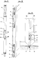
- Figure 1 is an elevational front view of a sliding bolt according to the present invention;
- Figure 2 is a partial view of a door to which two sliding bolts of different lengths according to the present invention are mounted;
- Figure 3 is a partial front view of a double-wing door including a partially sectioned detailed view of a locking element, of a safety lock applied to one wing, engaging with a sliding bolt according to the invention;
- Figures 4 and 5 are a front and a side longitudinal sectional view of a sliding bolt according to the present invention;
- Figures 6 and 7 are enlarged cross sectional view according to arrows VI-VI and VII-VII of figure 4 respectively.
- With reference to figure 1, a sliding bolt of the externally supported type generally indicated by 1 comprises an
elongated support 2 in which alatch 3 operated by alever 4 is slidingly engaged. - With reference to figure 2, the
sliding bolt 1 is mounted on adoor 5 by means ofscrews 6. In particular on thedoor 5 two slidingbolts 1 of different sizes are mounted, and the upper sliding bolt is longer in order to allow thelever 4 to be at a height which can be easily reached by anyone. - With reference to figures 1, 2 and 3, on the
support 2 of thesliding bolt 1 anopening 7 is made delimitating acavity 8 with alocking element 9 of asafety lock 10 can be engaged, as shown in figure 3. - With further reference to figure 3, a
sliding bolt 1 is mounted to onewing 5a ofdoor 5, thelatch 3 of which is shown engaging in ahousing 11 made in thethreshold 12. Thelocking element 9 oflock 10 is of the rotating type, the so-called "axe-type". For this reason, as shown in figure 1,cavity 8 has a substantially rectangular shape asymmetrical with respect to a transversal axis and in particular has a largerfirst portion 8a and a more narrowsecond portion 8b. - With reference to figures 1 and 3, the axe-
type locking element 9 during its rotation enters with a certain clearance in thefirst portion 8a and then, when the rotation is completed, is housed with precision in thesecond portion 8b. Clearly the shape just described ofcavity 8 is necessary only in the case of locks with rotating locking elements, whereas it is not necessary for locks with translating locking elements, wherecavity 8 can have a symmetrical rectangular shape. - With reference to figures 4 and 5, in order to form the
cavity 8 in whichlocking element 9 ofsafety lock 10 is housed,latch 3 is subdivided in two spacedportions arm 14 formed by twoparallel rods pins 15 are provided for to connect them to theportions latch 3. Insidesupport 2 of the sliding bolt abushing 16 is also fixed composed substantially of an elongated body in which there are formed thecavity 8 as well aslongitudinal guides portions latch 3 andpins 15. More precisely,guides cavity 8 since they help in the sliding theopposite portions respective pins 15.Guides 17 are, on the other hand, made on the sides of thecavity 8 in a transversal direction and positioned as close as possible to the edges of thesupport 2 so that they allow thecavity 8 to be wide enough to receive thelocking element 9. - With reference to figure 6, bushing 16 delimitates the
cavity 8 and fits in the opening 7 ofsupport 2. Furthermore, together with the support, it delimitatesguide 17 in which therod arm 14 are engaged. - With reference to figures 4 and 5,
holes 20 are formed on thebushing 16 through which thebushing 16 is fixed to thesupport 2 by means of screws 6 (visible in figure 1) which also have the function of fixing thesupport 2 of slidingbolt 1 to the door. In the case of locks with axe-type locking elements, thebushing 16, with exclusion of thecavity 8, is preferably symmetrical with respect to a transversal median axis. In this way, an upper sliding bolt can be transformed to a lower sliding bolt by simply rotating thebushing 16 with respect to support 2 thus keeping thenarrower portion 8b ofcavity 8 in a proper position (i.e. turned toward the floor) in both cases. - With reference to figure 3 according to the invention, it is possible to use a
sliding bolt 1 of any size and contemporaneously usesafety locks 10 placing them at the upper and lower ends of the door so that they have the maximum locking efficiency without interference with the sliding bolt used for securing the adjacent wing of the door.
Claims (4)
- Sliding bolt (1) of the externally supported type for door or window frames provided with a safety lock (10), comprising a latch (3) operated manually by means of a lever (4) and able to slide inside a support (2) mounted on the frame, characterized in that in said support (2) an opening (7) is formed fit for the passage of a locking element (9) of said safety lock (10), said latch (3) being divided in two spaced portions (3a, 3b) connected to one another in correspondence to said opening(?) by arm means (14) sliding on the sides of a bushing (16) housed in said support (2) and provided with a cavity (8) in which said locking element is engaged.
- Sliding bolt according to claim 1, wherein said arm means (14) comprises two parallel rods (14a, 14b) connected by means of pins (15) to said spaced portions (3a, 3b) of said latch (3), sliding guides (17, 18, 19) being provided for in said bushing (16) for said rods (14a, 14b), for said pins (15) and for the two portions (3a, 3b) of said latch (3).
- Sliding bolt according to claims 1 and 2, wherein said cavity (8) has a substantially rectangular shape asymmetrical with respect to a transversal axis and has a first wider (8a) and second more narrow (8b) portion in which the locking element (9) of the safety lock (10) engages during its passage and in the locked position respectively.
- Sliding bolt according to claims 1 to 3, wherein said bushing (16), with exclusion of said cavity (8), is symmetrical with respect to a transversal median axis, whereby it can be mounted on said support (2) in two different 180° rotated positions.
Applications Claiming Priority (2)
| Application Number | Priority Date | Filing Date | Title |
|---|---|---|---|
| IT000124 IT224504Z2 (en) | 1991-10-02 | 1991-10-02 | EXTERNAL LATCH BOLT FOR DOORS OR SIMILAR FRAMES WITH SEAT PERELEMENT TO LOCK A SECURITY LOCK |
| ITFI910124U | 1991-10-02 |
Publications (1)
| Publication Number | Publication Date |
|---|---|
| EP0537121A1 true EP0537121A1 (en) | 1993-04-14 |
Family
ID=11349654
Family Applications (1)
| Application Number | Title | Priority Date | Filing Date |
|---|---|---|---|
| EP92830538A Withdrawn EP0537121A1 (en) | 1991-10-02 | 1992-09-30 | Externally mounted sliding bolt for doors, windows or similar frames with an opening for the locking element of a safety lock |
Country Status (2)
| Country | Link |
|---|---|
| EP (1) | EP0537121A1 (en) |
| IT (1) | IT224504Z2 (en) |
Cited By (1)
| Publication number | Priority date | Publication date | Assignee | Title |
|---|---|---|---|---|
| EP1396596A1 (en) | 2002-09-06 | 2004-03-10 | Hawa Ag | Locking device for separating element |
Citations (5)
| Publication number | Priority date | Publication date | Assignee | Title |
|---|---|---|---|---|
| GB127972A (en) * | 1918-12-06 | 1919-06-19 | William Johnson Calder | Improvements relating to the Locking or Fastening of Double Doors. |
| US3771339A (en) * | 1972-01-24 | 1973-11-13 | E Smith | Protective apparatus for door locks employing latch-rods |
| US4283882A (en) * | 1979-10-17 | 1981-08-18 | Kawneer Company, Inc. | Safety flush bolt entrance door system |
| FR2598455A1 (en) * | 1986-05-09 | 1987-11-13 | Tirard Sa Jean | Method for blocking locking assemblies equipping opening panels, blocking device allowing this method to be implemented and assemblies provided with this device |
| DE9104645U1 (en) * | 1990-08-31 | 1991-06-27 | Aug. Winkhaus Gmbh & Co Kg, 4404 Telgte, De |
-
1991
- 1991-10-02 IT IT000124 patent/IT224504Z2/en active IP Right Grant
-
1992
- 1992-09-30 EP EP92830538A patent/EP0537121A1/en not_active Withdrawn
Patent Citations (5)
| Publication number | Priority date | Publication date | Assignee | Title |
|---|---|---|---|---|
| GB127972A (en) * | 1918-12-06 | 1919-06-19 | William Johnson Calder | Improvements relating to the Locking or Fastening of Double Doors. |
| US3771339A (en) * | 1972-01-24 | 1973-11-13 | E Smith | Protective apparatus for door locks employing latch-rods |
| US4283882A (en) * | 1979-10-17 | 1981-08-18 | Kawneer Company, Inc. | Safety flush bolt entrance door system |
| FR2598455A1 (en) * | 1986-05-09 | 1987-11-13 | Tirard Sa Jean | Method for blocking locking assemblies equipping opening panels, blocking device allowing this method to be implemented and assemblies provided with this device |
| DE9104645U1 (en) * | 1990-08-31 | 1991-06-27 | Aug. Winkhaus Gmbh & Co Kg, 4404 Telgte, De |
Cited By (2)
| Publication number | Priority date | Publication date | Assignee | Title |
|---|---|---|---|---|
| EP1396596A1 (en) | 2002-09-06 | 2004-03-10 | Hawa Ag | Locking device for separating element |
| US6851730B2 (en) | 2002-09-06 | 2005-02-08 | Hawa Ag | Device for locking a separative element |
Also Published As
| Publication number | Publication date |
|---|---|
| ITFI910124V0 (en) | 1991-10-02 |
| ITFI910124U1 (en) | 1993-04-02 |
| IT224504Z2 (en) | 1996-04-30 |
Similar Documents
| Publication | Publication Date | Title |
|---|---|---|
| US4488378A (en) | Building entrance | |
| US5255471A (en) | Friction stays | |
| US4046410A (en) | Four way security door | |
| US3779588A (en) | Sliding panel lock | |
| EP1703052A1 (en) | Interlocking mechanism for a window or the like | |
| EP0327264B1 (en) | Operating mechanism for closure fastening elements | |
| GB2125876A (en) | Improvements in or relating to hook locks for sliding doors and windows | |
| US4429912A (en) | Foldable security bar | |
| US1269311A (en) | Cremorne bolt. | |
| EP0167386A2 (en) | Securing system for a hinged panel | |
| ATE405719T1 (en) | SECURITY LOCK FOR DOOR | |
| GB2310245A (en) | Locks for windows and doors | |
| EP0537121A1 (en) | Externally mounted sliding bolt for doors, windows or similar frames with an opening for the locking element of a safety lock | |
| GB2289709A (en) | Espagnolette operating mechanism | |
| US4989908A (en) | Latching device for sliding door/window | |
| DE102016003138B4 (en) | burglar alarm | |
| US4272113A (en) | Sliding door safety bar | |
| GB2150972A (en) | Espagnolette operating mechanism | |
| GB2277958A (en) | Espagnolette fastening mechanism | |
| EP1679415B1 (en) | A locking mechanism and parts therefor | |
| US3197818A (en) | Awning window | |
| GB2343477A (en) | Door or window security device with two parts having cooperating projections and apertures | |
| ATE257894T1 (en) | LOCKING ROD FITTING FOR A WINDOW OR DOOR | |
| EP4332334A1 (en) | A reciprocating, sliding engagement mechanism for a window or door | |
| GB2337073A (en) | Shootbolt assembly with transmission members which are in tension during locking |
Legal Events
| Date | Code | Title | Description |
|---|---|---|---|
| PUAI | Public reference made under article 153(3) epc to a published international application that has entered the european phase |
Free format text: ORIGINAL CODE: 0009012 |
|
| AK | Designated contracting states |
Kind code of ref document: A1 Designated state(s): BE CH DE ES FR GR LI NL |
|
| 17P | Request for examination filed |
Effective date: 19930922 |
|
| 17Q | First examination report despatched |
Effective date: 19940920 |
|
| STAA | Information on the status of an ep patent application or granted ep patent |
Free format text: STATUS: THE APPLICATION IS DEEMED TO BE WITHDRAWN |
|
| 18D | Application deemed to be withdrawn |
Effective date: 19950131 |