EP0536920A1 - Container flusher - Google Patents
Container flusher Download PDFInfo
- Publication number
- EP0536920A1 EP0536920A1 EP92308705A EP92308705A EP0536920A1 EP 0536920 A1 EP0536920 A1 EP 0536920A1 EP 92308705 A EP92308705 A EP 92308705A EP 92308705 A EP92308705 A EP 92308705A EP 0536920 A1 EP0536920 A1 EP 0536920A1
- Authority
- EP
- European Patent Office
- Prior art keywords
- container
- conveyor
- flusher
- water tank
- water
- Prior art date
- Legal status (The legal status is an assumption and is not a legal conclusion. Google has not performed a legal analysis and makes no representation as to the accuracy of the status listed.)
- Granted
Links
Images




Classifications
-
- B—PERFORMING OPERATIONS; TRANSPORTING
- B08—CLEANING
- B08B—CLEANING IN GENERAL; PREVENTION OF FOULING IN GENERAL
- B08B9/00—Cleaning hollow articles by methods or apparatus specially adapted thereto
- B08B9/08—Cleaning containers, e.g. tanks
- B08B9/20—Cleaning containers, e.g. tanks by using apparatus into or on to which containers, e.g. bottles, jars, cans are brought
- B08B9/42—Cleaning containers, e.g. tanks by using apparatus into or on to which containers, e.g. bottles, jars, cans are brought the apparatus being characterised by means for conveying or carrying containers therethrough
-
- B—PERFORMING OPERATIONS; TRANSPORTING
- B08—CLEANING
- B08B—CLEANING IN GENERAL; PREVENTION OF FOULING IN GENERAL
- B08B3/00—Cleaning by methods involving the use or presence of liquid or steam
- B08B3/04—Cleaning involving contact with liquid
- B08B3/10—Cleaning involving contact with liquid with additional treatment of the liquid or of the object being cleaned, e.g. by heat, by electricity or by vibration
- B08B3/12—Cleaning involving contact with liquid with additional treatment of the liquid or of the object being cleaned, e.g. by heat, by electricity or by vibration by sonic or ultrasonic vibrations
- B08B3/123—Cleaning travelling work, e.g. webs, articles on a conveyor
- B08B3/126—Cleaning travelling work, e.g. webs, articles on a conveyor in particular moving bottles
-
- B—PERFORMING OPERATIONS; TRANSPORTING
- B08—CLEANING
- B08B—CLEANING IN GENERAL; PREVENTION OF FOULING IN GENERAL
- B08B9/00—Cleaning hollow articles by methods or apparatus specially adapted thereto
- B08B9/08—Cleaning containers, e.g. tanks
- B08B9/20—Cleaning containers, e.g. tanks by using apparatus into or on to which containers, e.g. bottles, jars, cans are brought
- B08B9/22—Cleaning containers, e.g. tanks by using apparatus into or on to which containers, e.g. bottles, jars, cans are brought the apparatus cleaning by soaking alone
- B08B9/24—Cleaning containers, e.g. tanks by using apparatus into or on to which containers, e.g. bottles, jars, cans are brought the apparatus cleaning by soaking alone and having conveyors
Definitions
- This invention relates to an apparatus for washing, rinsing or cooling containers such as ampoules, vials and bottles and which will subsequently be referred to as a flusher.
- Figure 9 of the attached drawings shows a typical container flusher of prior art.
- a container 62 to be flushed is fed and placed, in a standing posture, on the conveyor 61 which conveys, in turn, the container into a water tank 63.
- the container is filled with water injected from above through a nozzle 64.
- the container 62 is transferred at an outlet end of the conveyor from the conveyor onto a carrying plate 65 which is coupled to an ultrasonic transducer 66 to achieve a flushing effect.
- the container 62 is transferred by a lift conveyor 67 onto a conveyor 68 serving to convey the container 62 to a subsequent process.
- the ultrasonic waves are applied to a predetermined number of containers which are moving randomly while conveyed in a group. Therefore, not only the time for which the ultrasonic waves are applied to individual containers is uneven but also the amount of the ultrasonic waves applied to the bottom wall of each individual container is uneven, resulting in uneven flushing.
- the carrying plate 65 interposed between the container 62 and the ultrasonic vibrator 66 inevitably attenuates the ultrasonic waves and reduces a flushing efficiency.
- the container 62 is applied with the ultrasonic waves from its bottom and consequently its lower portion is exposed to the ultrasonic waves more intensely than the upper portion of the container 62. Thus glass exfoliation due to the ultrasonic wave often occurs in the lower portion of the container.
- a container flusher comprises: a conveyor adapted to convey the container along a circumferential path; guide means extending around said conveyor and frictionally contacting the side wall of said container so as to rotate said container around its own axis as said container is conveyed; a water tank in which the conveyor is at least partially water-immersed; and ultrasonic vibrators adapted to apply ultrasonic waves to the side wall of the container being rotated around its own axis by co-operation of said conveyor and said guide means within said water tank.
- the conveyor is provided on its outer peripheral surface with fin-like projections vertically extending and circumferentially spaced from one another at regular intervals; upper rails, sloped rails and lower rails extending around the conveyor so as to support the bottom of the container being conveyed; and guides associated with the respective rails.
- a nozzle used to fill the container with flushing water so that the container is immersed into the water tank for the application of ultrasonic waves.
- a heater below the water tank which heats the flushing water to enhance a flushing effect.
- the flusher of this invention allows the ultrasonic waves, whose output is controlled so as not to damage the glass of the container, to be applied onto the side wall of each container for a predetermined period of time as the container is rotated around its own axis under a frictional contact with the guides, so as to achieve an even flushing of the entire container and thereby to maintain an even quality.
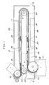
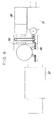
- Fig. 1 is a plan view of the ampoule flusher 50 and Fig. 2 is a side view including a sectional view taken along a line II - II in Fig. 1.
- a conveyor 11 of a relatively large width is draped around parts of respective timing pulleys 12, 13 within a water tank 10 and driven by the timing pulley 12 so as to be moved in a circumferential path counterclockwise (i.e., in the direction as indicated by an arrow in Fig. 1).
- reference symbol (I) designates an inlet end
- reference symbol (O) designates an outlet end of the conveyor 11.
- the conveyor 11 is provided on the outer peripheral surface thereof with fin-like projections 20 extending vertically and laterally spaced from one another at regular intervals so that an ampoule 21 is held between each pair of adjacent projections 20, 20 and the ampoule 21 is conveyed in the direction as indicated by the arrow in Figs. 1 and 2 as the conveyor 11 runs in the circumferential path.
- the upper rails extend at a relatively high level so as to be associated with the upper portion of the conveyor 11 and thereby to support the ampoule 21 above the water surface 39 while the lower rails extend at a relatively low level so as to be associated with the lower portion of the conveyor 11 and thereby to support ampoule 21 below the water surface 39.
- the sloped rails 23 serve to vary a position of the ampoule 21 gradually downward or upward between the respective upper rails 22 and the respective lower rails 24 as the conveyor 11 runs in its circumferential path. Configuration of the sloped rails 23 is not critical and may be non-linear.
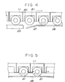
- an inlet end 27 of the guide 26 is slightly curved outward in order that the ampoule 21 can be smoothly transferred from the guide 25 to the guide 26.
- the guide 26 is brought in a frictional contact with the side wall of the ampoule 21 so that the ampoule 21 is rotated thereby around its own axis as the conveyor 11 runs in its circumferential path.
- a pair of ultrasonic vibrators 28 within the water tank 10 on both sides of the conveyor 11 so that the ampoule 21 which is held between the conveyor 11 and the guide 25 and is being conveyed may have its side wall applied with ultrasonic waves and thereby may be flushed.
- a nozzle 29 at the inlet end (I) of the conveyor 11 immediately above the sloped rail 23 and the container moving downward may be filled with flushing water 30 injected from the nozzle 29 as the conveyor 11 runs in its circumferential path as shown by Fig. 3(a).
- the sloped rails 23 may be eliminated as in the embodiment shown by Fig. 3(b) in which the upper rails 22 are arranged to be associated with the upper portion of the conveyor 11 and thereby to support the ampoule 21 above the water surface 39 while the lower rails 24 are arranged to be associated with the lower portion of the conveyor 11 and thereby to support the ampoule 21 below the water surface 39.
- the ampoule 21 vertically falls between each pair of the adjacent projections 20, 20 formed on the outer peripheral surface of the conveyor 11 when the ampoule 21 is transferred from the upper rail 22 to the lower rail 24.
- a location of the lower rail 24 onto which the ampoule 21 falls is provided in case with a shock-absorbing member 24′ made of rubber or the like.
- a star wheel 32 serving to transfer the ampoule 21 received from a feeder unit 31 onto the conveyor 11 of the flusher and there is provided adjacent the outlet end (O) of the conveyor 11 a star wheel 33 serving to feed the ampoule 21 received from the conveyor 11 of the flusher to the subsequent process.
- a heater 34 serving to maintain a water temperature within the water tank 10 about at 50 °C and thereby to enhance the flushing effect.
- the flusher of the invention having an arrangement as has been described above may be located, for example, as shown by Fig. 6 and various units such as the feeder unit 31, a jet flusher unit 36, a sterilizing dryer unit 37 and a water supply unit 38 in order to achieve efficient flushing of the container such as the ampoule.
- the flusher 50 of the invention operates in a manner as will be described.
- the ampoules 21 delivered from the feeder unit 31 to the star wheel 32 is fed at the inlet end (I) of the conveyor 11 into spaces defined between respective pairs of the adjacent projections 20, 20 formed on the outer peripheral surface of the conveyor 11.
- the ampoules 21 non supported by the upper rail 22 are conveyed in a line at a predetermined velocity in the direction as indicated by the arrow as the conveyor 11 runs in its circumferential path.
- these ampoules 21 are now conveyed by the conveyor 11 gradually downward toward the loner rail 24, as shown by Fig. 3(a). With the arrangement having no sloped rail 23, the ampoules 21 abruptly fall onto the lower rail 24, as shown by Fig. 3(b).
- the container 21 is filled with water 30 injected from the nozzle 29 provided thereabove when the container 21 is either on the upper rail 22 or being conveyed along the sloped rail 23. With the arrangement having no sloped rail 23. the nozzle 29 is provided above the upper rail 22 as shown by Fig. 3(b).
- the container 21 filled with water 30 is immersed in water further below the water surface 39 and perfectly immersed into the water tank 10 as the container 21 reaches the lower rail 24 as shown by Fig 3(a), 3(b).
- the container 21 After transferred onto the lower rail 24, the container 21 is held in the space defined between each pair of the adjacent projections 20, 20 formed on the outer peripheral surface of the conveyor 11 with the help of the guide 26, as shown by Fig. 5.
- the guide 26 comes in a frictional contact with the side wall of the container 21 and, under the effect of friction, the container 21 begins to be rotated around its own axis as the conveyor 11 runs.
- the side wall of the container 21 being conveyed is applied with the ultrasonic waves from a pair of the ultrasonic vibrators 28 provided on both sides of the conveyor 11, respectively.
- the container 21 being conveyed by the conveyor 11 and simultaneously rotated around its own axis under the frictional contact with the guide 26 can be evenly applied with the ultrasonic waves and thereby can be subjected to the efficient ultrasonic flushing.
- the ultrasonic flushing can be optimized for a particular size of the container to be flushed merely by adjusting a distance between the container 21 and the ultrasonic vibrators 28.
- no damage to the container will occur by controling the time and output of the application of ultrasonic waves when the container 21 are conveyed in a line at a predetermined velocity and applied onto their side walls with the ultrasonic waves for a predetermined period of time.
- the container 21 which has been thus adequately flushed is further conveyed by the conveyor 11, then transferred onto the sloped rail 23 provided on the opposite side and delivered to the star wheel 33 at the outlet end (O) of the conveyor 11.
- the container 21 is transferred to the subsequent process such as the jet flusher unit 36 or the sterilizing dryer unit 37.
- the nozzle used to fill the container with water or other liquid may be eliminated because the scaled container sinks under water by its own weight.
- a variant shown by Figs. 7 and 8 is a cooler, a requirement for sealed containers which have been heat-sterilized in an autoclave or an auto-sterilizer, to cool the containers during the conveyance to next stage.
- Fig. 7 is a plan view showing a cooler for a sealed container 42, which comprises components similar to those of the previously mentioned flusher of the invention, i.e., the components such as a water tank 40 and a conveyor 41.
- Fig. 8 is a side view including a sectional view taken along a line VIII - VIII.
- a cooling unit 43 having an outlet 44 and an inlet 45 for cooling water.
- the sealed container 42 has previously been filled with liquid and can sink under water within the water tank 40 as the conveyor 41 runs without a nozzle adapted to fill the container with water or other liquid.
- the sealed container 42 transferred from a feed star wheel 46 onto the conveyor 41 sinks into the water tank 40 as the conveyor 41 runs and, during conveyance, the sealed container 42 and the quantity of liquid contained therein are cooled by cooling water discharged from the cooling unit 43.
- the sealed container 42 thus cooled is delivered from the conveyor 41 to a discharging star wheel 47 which, in turn, delivers the container 42 to the subsequent process.
Landscapes
- Engineering & Computer Science (AREA)
- Mechanical Engineering (AREA)
- Cleaning In General (AREA)
- Cleaning By Liquid Or Steam (AREA)
- Apparatus For Disinfection Or Sterilisation (AREA)
- Filling Of Jars Or Cans And Processes For Cleaning And Sealing Jars (AREA)
- Devices That Are Associated With Refrigeration Equipment (AREA)
- Food Preservation Except Freezing, Refrigeration, And Drying (AREA)
- Attitude Control For Articles On Conveyors (AREA)
Abstract
Description
- This invention relates to an apparatus for washing, rinsing or cooling containers such as ampoules, vials and bottles and which will subsequently be referred to as a flusher.
- Figure 9 of the attached drawings shows a typical container flusher of prior art. At an inlet end of a
conveyor 61, acontainer 62 to be flushed is fed and placed, in a standing posture, on theconveyor 61 which conveys, in turn, the container into awater tank 63. In the course of such convenyance, the container is filled with water injected from above through anozzle 64. Then thecontainer 62 is transferred at an outlet end of the conveyor from the conveyor onto a carryingplate 65 which is coupled to anultrasonic transducer 66 to achieve a flushing effect. Upon completion of flushing, thecontainer 62 is transferred by alift conveyor 67 onto aconveyor 68 serving to convey thecontainer 62 to a subsequent process. - However, the above-mentioned flusher of prior art has encountered various problems as will be described.
- The ultrasonic waves are applied to a predetermined number of containers which are moving randomly while conveyed in a group. Therefore, not only the time for which the ultrasonic waves are applied to individual containers is uneven but also the amount of the ultrasonic waves applied to the bottom wall of each individual container is uneven, resulting in uneven flushing.
- The carrying
plate 65 interposed between thecontainer 62 and theultrasonic vibrator 66 inevitably attenuates the ultrasonic waves and reduces a flushing efficiency. - Finally, the
container 62 is applied with the ultrasonic waves from its bottom and consequently its lower portion is exposed to the ultrasonic waves more intensely than the upper portion of thecontainer 62. Thus glass exfoliation due to the ultrasonic wave often occurs in the lower portion of the container. - According to this invention a container flusher comprises:
a conveyor adapted to convey the container along a circumferential path;
guide means extending around said conveyor and frictionally contacting the side wall of said container so as to rotate said container around its own axis as said container is conveyed;
a water tank in which the conveyor is at least partially water-immersed; and
ultrasonic vibrators adapted to apply ultrasonic waves to the side wall of the container being rotated around its own axis by co-operation of said conveyor and said guide means within said water tank. - Preferably, the conveyor is provided on its outer peripheral surface with fin-like projections vertically extending and circumferentially spaced from one another at regular intervals; upper rails, sloped rails and lower rails extending around the conveyor so as to support the bottom of the container being conveyed; and guides associated with the respective rails.
- If desired, there may be provided above the conveyor a nozzle used to fill the container with flushing water so that the container is immersed into the water tank for the application of ultrasonic waves. In addition, there may be provided a heater below the water tank which heats the flushing water to enhance a flushing effect.
- The flusher of this invention allows the ultrasonic waves, whose output is controlled so as not to damage the glass of the container, to be applied onto the side wall of each container for a predetermined period of time as the container is rotated around its own axis under a frictional contact with the guides, so as to achieve an even flushing of the entire container and thereby to maintain an even quality.
- Thus it is a principal advantage of the present invention providing means allowing each container to be efficiently and evenly flushed by evenly applying ultrasonic waves onto a side wall of the container for a predetermined period of time.
- Application of the ultrasonic waves taking place directly onto the container assures an efficient flushing process.
- Particular embodiments of flushers in accordance with this invention will now be described with reference to the accompanying drawings, in which:-
- Fig. 1 is a plan view showing an embodiment of an
ampoule flusher 50 constructed according to the invention; - Fig. 2 is a side view showing the
flusher 50 partially in a section taken along a line II - II in Fig. 1; - Fig 3(a) is a side view showing a relationship of the
upper rail 22, the slopedrail 23 and thelower rail 24; - Fig. 3(b) is a side view showing a relationship between the
upper rail 22 and thelower rail 24 in an alternative embodiment with respect to the embodiment shown by Figure. 3(a); - Fig. 4 is a plan view showing a relationship between the
guide 25 and aninlet end 27 of theadjacent guide 26; - Fig. 5 is a plan view showing a manner in which the
guide 26 is brought in a frictional contact with the side wall of the container; - Fig. 6 is a diagram showing the
flusher 50 of the invention arranged in association with relevant peripheral apparatuses; - Fig. 7 is a plan view of a cooler diverted from the flusher of the invention;
- Fig. 8 is a side view partially in a section taken along a line VIII - VIII in Fig. 7; and
- Fig. 9 is a diagram schematically showing a flusher of prior art.
- Although the invention will be described first with respect to the ampoule as an example of the sealed container, it should be understood here that the invention is not limited to this and applicable also to containers of the other various types such as vial, bottle and phial so far as they have substantially circular or elliptical cross-sections.
- Fig. 1 is a plan view of the
ampoule flusher 50 and Fig. 2 is a side view including a sectional view taken along a line II - II in Fig. 1. - Referring to these figures, the
flusher 50 of the invention will be described in detail. A conveyor 11 of a relatively large width is draped around parts ofrespective timing pulleys water tank 10 and driven by thetiming pulley 12 so as to be moved in a circumferential path counterclockwise (i.e., in the direction as indicated by an arrow in Fig. 1). Referring to Fig. 1, reference symbol (I) designates an inlet end and reference symbol (O) designates an outlet end of the conveyor 11. - As will be apparent from Fig. 2, rotation of an
electric motor 14 provided below thewater tank 10 is transmitted viabelts output shaft 17, on one side. and via abelt 18 to adrive shaft 19 of thetiming pulley 12. - The conveyor 11 is provided on the outer peripheral surface thereof with fin-
like projections 20 extending vertically and laterally spaced from one another at regular intervals so that anampoule 21 is held between each pair ofadjacent projections ampoule 21 is conveyed in the direction as indicated by the arrow in Figs. 1 and 2 as the conveyor 11 runs in the circumferential path. - Around the conveyor 11, there are provided
upper rails 22, slopedrails 23 andlower rails 24 so that theampoule 21 has its bottom supported by theserails ampoule 21 is conveyed. Referring to Fig. 3(a), the upper rails extend at a relatively high level so as to be associated with the upper portion of the conveyor 11 and thereby to support theampoule 21 above thewater surface 39 while the lower rails extend at a relatively low level so as to be associated with the lower portion of the conveyor 11 and thereby to supportampoule 21 below thewater surface 39. The slopedrails 23 serve to vary a position of theampoule 21 gradually downward or upward between the respectiveupper rails 22 and the respectivelower rails 24 as the conveyor 11 runs in its circumferential path. Configuration of thesloped rails 23 is not critical and may be non-linear. - There are provided along the outside of the conveyor 11
guides ampoule 21 supported by theupper rails 22 or the slopedrails 23 between each pair of theadjacent projections ampoule 21 supported by thelower rails 24 between each pair of theadjacent projections - Now referring to Fig. 4, an
inlet end 27 of theguide 26 is slightly curved outward in order that theampoule 21 can be smoothly transferred from theguide 25 to theguide 26. As well be seen in Fig. 5, theguide 26 is brought in a frictional contact with the side wall of theampoule 21 so that theampoule 21 is rotated thereby around its own axis as the conveyor 11 runs in its circumferential path. - Referring again to Figs. 1 and 2, there are provided a pair of
ultrasonic vibrators 28 within thewater tank 10 on both sides of the conveyor 11 so that theampoule 21 which is held between the conveyor 11 and theguide 25 and is being conveyed may have its side wall applied with ultrasonic waves and thereby may be flushed. - For a non-sealed container, there may be provided a
nozzle 29 at the inlet end (I) of the conveyor 11 immediately above the slopedrail 23 and the container moving downward may be filled with flushingwater 30 injected from thenozzle 29 as the conveyor 11 runs in its circumferential path as shown by Fig. 3(a). - Alternatively, the
sloped rails 23 may be eliminated as in the embodiment shown by Fig. 3(b) in which theupper rails 22 are arranged to be associated with the upper portion of the conveyor 11 and thereby to support theampoule 21 above thewater surface 39 while thelower rails 24 are arranged to be associated with the lower portion of the conveyor 11 and thereby to support theampoule 21 below thewater surface 39. In this embodiment, theampoule 21 vertically falls between each pair of theadjacent projections ampoule 21 is transferred from theupper rail 22 to thelower rail 24. In this alternative embodiment, while water itself in the water tank has a shock-absorbing function, a location of thelower rail 24 onto which theampoule 21 falls is provided in case with a shock-absorbingmember 24′ made of rubber or the like. - Referring again to Fig. 1, there is provided adjacent the inlet end (I) of the conveyor 11 a
star wheel 32 serving to transfer theampoule 21 received from afeeder unit 31 onto the conveyor 11 of the flusher and there is provided adjacent the outlet end (O) of the conveyor 11 astar wheel 33 serving to feed theampoule 21 received from the conveyor 11 of the flusher to the subsequent process. Referring to Fig. 2, there is provided below the water tank 10 aheater 34 serving to maintain a water temperature within thewater tank 10 about at 50 °C and thereby to enhance the flushing effect. - The flusher of the invention having an arrangement as has been described above may be located, for example, as shown by Fig. 6 and various units such as the
feeder unit 31, ajet flusher unit 36, asterilizing dryer unit 37 and awater supply unit 38 in order to achieve efficient flushing of the container such as the ampoule. - The
flusher 50 of the invention operates in a manner as will be described. Referring to Fig. 1, theampoules 21 delivered from thefeeder unit 31 to thestar wheel 32 is fed at the inlet end (I) of the conveyor 11 into spaces defined between respective pairs of theadjacent projections ampoules 21 non supported by theupper rail 22 are conveyed in a line at a predetermined velocity in the direction as indicated by the arrow as the conveyor 11 runs in its circumferential path. After transferred from theupper rail 22 onto the slopedrail 23, theseampoules 21 are now conveyed by the conveyor 11 gradually downward toward theloner rail 24, as shown by Fig. 3(a). With the arrangement having no slopedrail 23, theampoules 21 abruptly fall onto thelower rail 24, as shown by Fig. 3(b). - For the
non-sealed container 21, thecontainer 21 is filled withwater 30 injected from thenozzle 29 provided thereabove when thecontainer 21 is either on theupper rail 22 or being conveyed along thesloped rail 23. With the arrangement having no slopedrail 23. thenozzle 29 is provided above theupper rail 22 as shown by Fig. 3(b). - The
container 21 filled withwater 30 is immersed in water further below thewater surface 39 and perfectly immersed into thewater tank 10 as thecontainer 21 reaches thelower rail 24 as shown by Fig 3(a), 3(b). - After transferred onto the
lower rail 24, thecontainer 21 is held in the space defined between each pair of theadjacent projections guide 26, as shown by Fig. 5. In this state, theguide 26 comes in a frictional contact with the side wall of thecontainer 21 and, under the effect of friction, thecontainer 21 begins to be rotated around its own axis as the conveyor 11 runs. The side wall of thecontainer 21 being conveyed is applied with the ultrasonic waves from a pair of theultrasonic vibrators 28 provided on both sides of the conveyor 11, respectively. In this way, thecontainer 21 being conveyed by the conveyor 11 and simultaneously rotated around its own axis under the frictional contact with theguide 26 can be evenly applied with the ultrasonic waves and thereby can be subjected to the efficient ultrasonic flushing. Furthermore, the ultrasonic flushing can be optimized for a particular size of the container to be flushed merely by adjusting a distance between thecontainer 21 and theultrasonic vibrators 28. Also, no damage to the container will occur by controling the time and output of the application of ultrasonic waves when thecontainer 21 are conveyed in a line at a predetermined velocity and applied onto their side walls with the ultrasonic waves for a predetermined period of time. - The
container 21 which has been thus adequately flushed is further conveyed by the conveyor 11, then transferred onto the slopedrail 23 provided on the opposite side and delivered to thestar wheel 33 at the outlet end (O) of the conveyor 11. - Finally, the
container 21 is transferred to the subsequent process such as thejet flusher unit 36 or the sterilizingdryer unit 37. For the sealed container, the nozzle used to fill the container with water or other liquid may be eliminated because the scaled container sinks under water by its own weight. - A variant shown by Figs. 7 and 8 is a cooler, a requirement for sealed containers which have been heat-sterilized in an autoclave or an auto-sterilizer, to cool the containers during the conveyance to next stage.
- Fig. 7 is a plan view showing a cooler for a sealed
container 42, which comprises components similar to those of the previously mentioned flusher of the invention, i.e., the components such as awater tank 40 and aconveyor 41. Fig. 8 is a side view including a sectional view taken along a line VIII - VIII. Within thewater tank 40, there is provided acooling unit 43 having anoutlet 44 and aninlet 45 for cooling water. The sealedcontainer 42 has previously been filled with liquid and can sink under water within thewater tank 40 as theconveyor 41 runs without a nozzle adapted to fill the container with water or other liquid. - With such cooler, the sealed
container 42 transferred from afeed star wheel 46 onto theconveyor 41 sinks into thewater tank 40 as theconveyor 41 runs and, during conveyance, the sealedcontainer 42 and the quantity of liquid contained therein are cooled by cooling water discharged from the coolingunit 43. The sealedcontainer 42 thus cooled is delivered from theconveyor 41 to a dischargingstar wheel 47 which, in turn, delivers thecontainer 42 to the subsequent process. - Furthermore, adding ultrasonic vibrators, which apply ultrasonic waves to the side wall of the container, to this cooler makes it possible to flush the outside of containers while cooling them.
Claims (9)
- A container flusher (50) comprising:
a conveyor (11) adapted to convey the container (21) along a circumferential path;
guide means (25, 26) extending around said conveyor (11) and frictionally contacting the side wall of said container (21) so as to rotate said container (21) around its own axis as said container (21) is conveyed;
a water tank (10) in which the conveyor (11) is at least partially water-immersed; and
ultrasonic vibrators (28) adapted to apply ultrasonic waves to the side wall of the container (21) being rotated around its own axis by co-operation of said conveyor (11) and said guide means (25, 26) within said water tank (10). - A container flusher as recited in claim 1, wherein the conveyor (11) is provided on its outer peripheral surface with fin-like projections (20) vertically extending and circumferentially spaced from one another at regular intervals.
- A container flusher as recited in claim 1 or 2, wherein there are provided around the conveyor (11) upper rails (22) and lower rails (24) both adapted to support the bottom of the containers (21) and wherein said lower rails (24) are immersed in water within the water tank (10).
- A container flusher as recited in claim 3, further comprising a sloped rail (23) interposed between said lower (24) and upper (22) rails.
- A container flusher as recited in claim 3 or 4, in which the guide means (25, 26) are associated with the upper (22) and lower (24) rails, and, where present, the sloping rails (23).
- A container flusher as recited in any preceding claim, further comprising a nozzle (29) provided above the conveyor (11) so that the container (21) is filled with flushing liquid such as water injected through said nozzle (29).
- A container flusher as recited in any preceding claim, further comprising a heater (34) provided below the water tank (10).
- A container flusher as recited in any one of claims 1 to 6, further comprising a cooling unit (43) provided within said water tank (10) and having an inlet (44) and an outlet (45).
- A container flusher comprising:
a conveyor (11) adapted to convey the container (21) along a circumferential path;
guide means (25, 26) extending around said conveyor (11) and frictionally contacting the side wall of said container (21) so as to rotate said container (21) around its own axis as said container (21) is conveyed;
a water tank (10) in which the conveyor (11) is at least partially water-immersed; and
a cooling unit (43) provided within said water tank (10) and having an inlet (44) and an outlet (45) for cooling water.
Priority Applications (1)
| Application Number | Priority Date | Filing Date | Title |
|---|---|---|---|
| EP95200515A EP0661111B1 (en) | 1991-10-09 | 1992-09-24 | Container cooler |
Applications Claiming Priority (2)
| Application Number | Priority Date | Filing Date | Title |
|---|---|---|---|
| JP290835/91 | 1991-10-09 | ||
| JP29083591A JP3297064B2 (en) | 1991-10-09 | 1991-10-09 | Container cleaning equipment |
Related Child Applications (2)
| Application Number | Title | Priority Date | Filing Date |
|---|---|---|---|
| EP95200515A Division EP0661111B1 (en) | 1991-10-09 | 1992-09-24 | Container cooler |
| EP95200515.5 Division-Into | 1992-09-24 |
Publications (2)
| Publication Number | Publication Date |
|---|---|
| EP0536920A1 true EP0536920A1 (en) | 1993-04-14 |
| EP0536920B1 EP0536920B1 (en) | 1996-07-31 |
Family
ID=17761106
Family Applications (2)
| Application Number | Title | Priority Date | Filing Date |
|---|---|---|---|
| EP95200515A Expired - Lifetime EP0661111B1 (en) | 1991-10-09 | 1992-09-24 | Container cooler |
| EP92308705A Expired - Lifetime EP0536920B1 (en) | 1991-10-09 | 1992-09-24 | Container flusher |
Family Applications Before (1)
| Application Number | Title | Priority Date | Filing Date |
|---|---|---|---|
| EP95200515A Expired - Lifetime EP0661111B1 (en) | 1991-10-09 | 1992-09-24 | Container cooler |
Country Status (6)
| Country | Link |
|---|---|
| US (1) | US5316030A (en) |
| EP (2) | EP0661111B1 (en) |
| JP (1) | JP3297064B2 (en) |
| KR (1) | KR930007525A (en) |
| DE (2) | DE69226288T2 (en) |
| TW (1) | TW203019B (en) |
Cited By (4)
| Publication number | Priority date | Publication date | Assignee | Title |
|---|---|---|---|---|
| WO2003082488A1 (en) * | 2002-03-28 | 2003-10-09 | Krones Ag | Method and device for the treatment of plastic bottles |
| EP3666404A1 (en) * | 2018-12-13 | 2020-06-17 | Gebo Packaging Solutions Italy SRL | A washing machine for washing empty containers and an operating method thereof |
| EP3666403A1 (en) * | 2018-12-13 | 2020-06-17 | Gebo Packaging Solutions Italy SRL | A washing machine for washing empty containers and an operating method thereof |
| KR102777439B1 (en) * | 2024-01-30 | 2025-03-05 | 황상철 | vial washer |
Families Citing this family (12)
| Publication number | Priority date | Publication date | Assignee | Title |
|---|---|---|---|---|
| DE4425765C2 (en) * | 1994-07-21 | 1999-01-07 | Duerr Systems Gmbh | System for cleaning workpieces using a compressed air jet |
| DE19702716C2 (en) * | 1997-01-25 | 1999-08-19 | Em Geraetebau Ruecknahmesystem | Device for transporting objects |
| JP3213842B2 (en) * | 1998-09-04 | 2001-10-02 | 日本クラウンコルク株式会社 | Container cleaning method |
| AU779509B2 (en) * | 1999-12-30 | 2005-01-27 | Japan Crown Cork Co. Ltd. | Method for washing container |
| JP2007069052A (en) * | 2005-09-02 | 2007-03-22 | Ishizuka Glass Co Ltd | Ultrasonic cleaning apparatus, ultrasonic cleaning method, and manufacturing method of cleaned product |
| DE102008015815A1 (en) * | 2008-03-27 | 2009-10-01 | Wincor Nixdorf International Gmbh | Reverse vending machine |
| CN101259470B (en) * | 2008-04-23 | 2010-06-16 | 孙志武 | Automatic bottle washing machine for special-shaped bottles |
| CN103193081A (en) * | 2012-01-09 | 2013-07-10 | 上海华东制药机械有限公司 | Lifting wheel body of bottle washer with double bottle feeding tracks |
| CN103599911B (en) * | 2013-12-05 | 2016-01-20 | 镇江市顶智微电子科技有限公司 | A kind ofly rinse the method for washing filling bottle |
| CN112517578A (en) * | 2020-12-17 | 2021-03-19 | 巨石集团有限公司 | Automatic cleaning equipment for wire winding barrel |
| EP4286067B1 (en) * | 2022-05-30 | 2026-01-28 | Sidel Participations | Washing machine for washing empty containers adapted to be filled with a pourable product |
| DE102022003000A1 (en) * | 2022-08-17 | 2024-02-22 | Kocher-Plastik Maschinenbau Gmbh | contraption |
Citations (3)
| Publication number | Priority date | Publication date | Assignee | Title |
|---|---|---|---|---|
| US3090392A (en) * | 1960-12-19 | 1963-05-21 | Hugh H Libby | Label removing apparatus |
| GB1171652A (en) * | 1966-01-29 | 1969-11-26 | Seitz Werke Gmbh | Improvements in or relating to Bottle Cleaning Machines |
| FR2366215A1 (en) * | 1976-07-26 | 1978-04-28 | Appelshauser Charles | Round tin washing machine - has guide members leaving nearly all faces free and has guides for rotating tins |
Family Cites Families (7)
| Publication number | Priority date | Publication date | Assignee | Title |
|---|---|---|---|---|
| US2494864A (en) * | 1946-11-18 | 1950-01-17 | Cal Grove Products Co | Can cooling machine |
| US2811163A (en) * | 1949-12-16 | 1957-10-29 | Armour & Co | Article washing apparatus |
| US2910992A (en) * | 1958-07-15 | 1959-11-03 | Martin J Wilcox | Can washer |
| US3302655A (en) * | 1963-12-30 | 1967-02-07 | Nibon Seikosho Kk | Apparatus for spraying and ultrasonic washing of bottles |
| US3572490A (en) * | 1969-04-01 | 1971-03-30 | Barry Wehmiller Co | Container handling apparatus |
| US3618743A (en) * | 1969-11-05 | 1971-11-09 | Mead Corp | Article-orienting device |
| DE3001986C2 (en) * | 1980-01-21 | 1986-08-14 | Fa. Heinr. Leicht, 8600 Bamberg | Method and device for cleaning bottles |
-
1991
- 1991-10-09 JP JP29083591A patent/JP3297064B2/en not_active Expired - Fee Related
-
1992
- 1992-09-21 US US07/947,454 patent/US5316030A/en not_active Expired - Fee Related
- 1992-09-24 EP EP95200515A patent/EP0661111B1/en not_active Expired - Lifetime
- 1992-09-24 DE DE69226288T patent/DE69226288T2/en not_active Expired - Fee Related
- 1992-09-24 DE DE69212558T patent/DE69212558T2/en not_active Expired - Fee Related
- 1992-09-24 EP EP92308705A patent/EP0536920B1/en not_active Expired - Lifetime
- 1992-10-07 TW TW081107983A patent/TW203019B/zh active
- 1992-10-09 KR KR1019920018578A patent/KR930007525A/en not_active Ceased
Patent Citations (3)
| Publication number | Priority date | Publication date | Assignee | Title |
|---|---|---|---|---|
| US3090392A (en) * | 1960-12-19 | 1963-05-21 | Hugh H Libby | Label removing apparatus |
| GB1171652A (en) * | 1966-01-29 | 1969-11-26 | Seitz Werke Gmbh | Improvements in or relating to Bottle Cleaning Machines |
| FR2366215A1 (en) * | 1976-07-26 | 1978-04-28 | Appelshauser Charles | Round tin washing machine - has guide members leaving nearly all faces free and has guides for rotating tins |
Cited By (6)
| Publication number | Priority date | Publication date | Assignee | Title |
|---|---|---|---|---|
| WO2003082488A1 (en) * | 2002-03-28 | 2003-10-09 | Krones Ag | Method and device for the treatment of plastic bottles |
| EP3666404A1 (en) * | 2018-12-13 | 2020-06-17 | Gebo Packaging Solutions Italy SRL | A washing machine for washing empty containers and an operating method thereof |
| EP3666403A1 (en) * | 2018-12-13 | 2020-06-17 | Gebo Packaging Solutions Italy SRL | A washing machine for washing empty containers and an operating method thereof |
| WO2020119958A1 (en) * | 2018-12-13 | 2020-06-18 | Sidel End Of Line & Tunnels Solutions Srl | A washing machine for washing empty containers and an operating method thereof |
| WO2020120695A1 (en) * | 2018-12-13 | 2020-06-18 | Sidel End Of Line & Tunnels Solutions | A washing machine for washing empty containers and an operating method thereof |
| KR102777439B1 (en) * | 2024-01-30 | 2025-03-05 | 황상철 | vial washer |
Also Published As
| Publication number | Publication date |
|---|---|
| EP0661111B1 (en) | 1998-07-15 |
| JP3297064B2 (en) | 2002-07-02 |
| KR930007525A (en) | 1993-05-20 |
| DE69226288D1 (en) | 1998-08-20 |
| US5316030A (en) | 1994-05-31 |
| TW203019B (en) | 1993-04-01 |
| EP0536920B1 (en) | 1996-07-31 |
| EP0661111A3 (en) | 1995-07-26 |
| DE69212558T2 (en) | 1996-11-28 |
| EP0661111A2 (en) | 1995-07-05 |
| JPH0596259A (en) | 1993-04-20 |
| DE69226288T2 (en) | 1998-11-19 |
| DE69212558D1 (en) | 1996-09-05 |
Similar Documents
| Publication | Publication Date | Title |
|---|---|---|
| US5316030A (en) | Container flusher | |
| EP1128733A1 (en) | Apparatus and methods for transferring heat between a heat transfer liquid and a plurality of product containers | |
| CN1017697B (en) | Method and apparatus for conveying various containers | |
| EP3666403A1 (en) | A washing machine for washing empty containers and an operating method thereof | |
| JP2003118793A (en) | System for handling container | |
| CN105110272A (en) | Method for rinsing, screening, conveying, bottling, sealing, capping and labeling pharmaceutical, chemical or biological reagent bottles | |
| US3677273A (en) | Bottle rinsing apparatus | |
| JPS6322873B2 (en) | ||
| US1270797A (en) | Canning. | |
| US3298404A (en) | Machine and method for filling containers to a predetermined level | |
| EP0141572A2 (en) | Apparatus for packaging an edible liquid | |
| US3559563A (en) | Bottling apparatus and method | |
| US3157011A (en) | Air elimination method and apparatus | |
| CN113367574B (en) | A fully automatic cooking system | |
| CN117049171B (en) | Pasteurization production line for food material packaging finished product | |
| US2043763A (en) | Container handling machine | |
| JPH11278594A (en) | Liquid filling device | |
| JP3979267B2 (en) | Sterilizer for bottled beverages | |
| JP2002274636A (en) | Apparatus and method for transporting objects such as bottles | |
| US1098551A (en) | Pastetjbizijig apparates | |
| CN223737682U (en) | Natural water filling equipment drinks | |
| JP3918250B2 (en) | Conveyor device | |
| US3901294A (en) | Container filler with excess product removal assembly | |
| KR100792680B1 (en) | Filling device | |
| CN214084835U (en) | A conveying mechanism for a filling machine |
Legal Events
| Date | Code | Title | Description |
|---|---|---|---|
| PUAI | Public reference made under article 153(3) epc to a published international application that has entered the european phase |
Free format text: ORIGINAL CODE: 0009012 |
|
| AK | Designated contracting states |
Kind code of ref document: A1 Designated state(s): BE CH DE FR GB IT LI NL SE |
|
| 17P | Request for examination filed |
Effective date: 19930930 |
|
| 17Q | First examination report despatched |
Effective date: 19941125 |
|
| GRAH | Despatch of communication of intention to grant a patent |
Free format text: ORIGINAL CODE: EPIDOS IGRA |
|
| GRAH | Despatch of communication of intention to grant a patent |
Free format text: ORIGINAL CODE: EPIDOS IGRA |
|
| GRAA | (expected) grant |
Free format text: ORIGINAL CODE: 0009210 |
|
| AK | Designated contracting states |
Kind code of ref document: B1 Designated state(s): BE CH DE FR GB IT LI NL SE |
|
| DX | Miscellaneous (deleted) | ||
| PG25 | Lapsed in a contracting state [announced via postgrant information from national office to epo] |
Ref country code: NL Free format text: LAPSE BECAUSE OF FAILURE TO SUBMIT A TRANSLATION OF THE DESCRIPTION OR TO PAY THE FEE WITHIN THE PRESCRIBED TIME-LIMIT Effective date: 19960731 Ref country code: BE Effective date: 19960731 |
|
| REG | Reference to a national code |
Ref country code: CH Ref legal event code: NV Representative=s name: E. BLUM & CO. PATENTANWAELTE |
|
| REF | Corresponds to: |
Ref document number: 69212558 Country of ref document: DE Date of ref document: 19960905 |
|
| ITF | It: translation for a ep patent filed | ||
| ET | Fr: translation filed | ||
| PGFP | Annual fee paid to national office [announced via postgrant information from national office to epo] |
Ref country code: CH Payment date: 19961004 Year of fee payment: 5 |
|
| PG25 | Lapsed in a contracting state [announced via postgrant information from national office to epo] |
Ref country code: SE Effective date: 19961031 |
|
| NLV1 | Nl: lapsed or annulled due to failure to fulfill the requirements of art. 29p and 29m of the patents act | ||
| PLBE | No opposition filed within time limit |
Free format text: ORIGINAL CODE: 0009261 |
|
| 26N | No opposition filed | ||
| PG25 | Lapsed in a contracting state [announced via postgrant information from national office to epo] |
Ref country code: LI Free format text: LAPSE BECAUSE OF NON-PAYMENT OF DUE FEES Effective date: 19970930 Ref country code: CH Free format text: LAPSE BECAUSE OF NON-PAYMENT OF DUE FEES Effective date: 19970930 |
|
| REG | Reference to a national code |
Ref country code: CH Ref legal event code: PL |
|
| PGFP | Annual fee paid to national office [announced via postgrant information from national office to epo] |
Ref country code: FR Payment date: 19980909 Year of fee payment: 7 |
|
| PGFP | Annual fee paid to national office [announced via postgrant information from national office to epo] |
Ref country code: GB Payment date: 19981001 Year of fee payment: 7 |
|
| PGFP | Annual fee paid to national office [announced via postgrant information from national office to epo] |
Ref country code: DE Payment date: 19981005 Year of fee payment: 7 |
|
| PG25 | Lapsed in a contracting state [announced via postgrant information from national office to epo] |
Ref country code: GB Free format text: LAPSE BECAUSE OF NON-PAYMENT OF DUE FEES Effective date: 19990924 |
|
| GBPC | Gb: european patent ceased through non-payment of renewal fee |
Effective date: 19990924 |
|
| PG25 | Lapsed in a contracting state [announced via postgrant information from national office to epo] |
Ref country code: FR Free format text: LAPSE BECAUSE OF NON-PAYMENT OF DUE FEES Effective date: 20000531 |
|
| PG25 | Lapsed in a contracting state [announced via postgrant information from national office to epo] |
Ref country code: DE Free format text: LAPSE BECAUSE OF NON-PAYMENT OF DUE FEES Effective date: 20000701 |
|
| REG | Reference to a national code |
Ref country code: FR Ref legal event code: ST |
|
| PG25 | Lapsed in a contracting state [announced via postgrant information from national office to epo] |
Ref country code: IT Free format text: LAPSE BECAUSE OF NON-PAYMENT OF DUE FEES Effective date: 20050924 |