EP0536785B1 - Multi-stage storage case for cassettes or cassette blocks - Google Patents
Multi-stage storage case for cassettes or cassette blocks Download PDFInfo
- Publication number
- EP0536785B1 EP0536785B1 EP92117316A EP92117316A EP0536785B1 EP 0536785 B1 EP0536785 B1 EP 0536785B1 EP 92117316 A EP92117316 A EP 92117316A EP 92117316 A EP92117316 A EP 92117316A EP 0536785 B1 EP0536785 B1 EP 0536785B1
- Authority
- EP
- European Patent Office
- Prior art keywords
- drawer
- cassettes
- unit
- storage case
- shelf
- Prior art date
- Legal status (The legal status is an assumption and is not a legal conclusion. Google has not performed a legal analysis and makes no representation as to the accuracy of the status listed.)
- Expired - Lifetime
Links
Images


Classifications
-
- A—HUMAN NECESSITIES
- A61—MEDICAL OR VETERINARY SCIENCE; HYGIENE
- A61B—DIAGNOSIS; SURGERY; IDENTIFICATION
- A61B50/00—Containers, covers, furniture or holders specially adapted for surgical or diagnostic appliances or instruments, e.g. sterile covers
- A61B50/10—Furniture specially adapted for surgical or diagnostic appliances or instruments
- A61B50/18—Cupboards; Drawers therefor
-
- A—HUMAN NECESSITIES
- A61—MEDICAL OR VETERINARY SCIENCE; HYGIENE
- A61B—DIAGNOSIS; SURGERY; IDENTIFICATION
- A61B50/00—Containers, covers, furniture or holders specially adapted for surgical or diagnostic appliances or instruments, e.g. sterile covers
- A61B50/10—Furniture specially adapted for surgical or diagnostic appliances or instruments
-
- A—HUMAN NECESSITIES
- A47—FURNITURE; DOMESTIC ARTICLES OR APPLIANCES; COFFEE MILLS; SPICE MILLS; SUCTION CLEANERS IN GENERAL
- A47B—TABLES; DESKS; OFFICE FURNITURE; CABINETS; DRAWERS; GENERAL DETAILS OF FURNITURE
- A47B87/00—Sectional furniture, i.e. combinations of complete furniture units, e.g. assemblies of furniture units of the same kind such as linkable cabinets, tables, racks or shelf units
- A47B87/02—Sectional furniture, i.e. combinations of complete furniture units, e.g. assemblies of furniture units of the same kind such as linkable cabinets, tables, racks or shelf units stackable ; stackable and linkable
- A47B87/0207—Stackable racks, trays or shelf units
-
- A—HUMAN NECESSITIES
- A47—FURNITURE; DOMESTIC ARTICLES OR APPLIANCES; COFFEE MILLS; SPICE MILLS; SUCTION CLEANERS IN GENERAL
- A47B—TABLES; DESKS; OFFICE FURNITURE; CABINETS; DRAWERS; GENERAL DETAILS OF FURNITURE
- A47B87/00—Sectional furniture, i.e. combinations of complete furniture units, e.g. assemblies of furniture units of the same kind such as linkable cabinets, tables, racks or shelf units
- A47B87/02—Sectional furniture, i.e. combinations of complete furniture units, e.g. assemblies of furniture units of the same kind such as linkable cabinets, tables, racks or shelf units stackable ; stackable and linkable
- A47B87/0284—Cabinet systems consisting of stacked-and-linked uniform casings, each being a cabinet or drawer-holder, e.g. lockers, mail/file boxing systems
-
- A—HUMAN NECESSITIES
- A47—FURNITURE; DOMESTIC ARTICLES OR APPLIANCES; COFFEE MILLS; SPICE MILLS; SUCTION CLEANERS IN GENERAL
- A47B—TABLES; DESKS; OFFICE FURNITURE; CABINETS; DRAWERS; GENERAL DETAILS OF FURNITURE
- A47B88/00—Drawers for tables, cabinets or like furniture; Guides for drawers
- A47B88/40—Sliding drawers; Slides or guides therefor
- A47B88/417—Profiled cabinet walls with grooves or protuberances for supporting drawers
-
- A—HUMAN NECESSITIES
- A47—FURNITURE; DOMESTIC ARTICLES OR APPLIANCES; COFFEE MILLS; SPICE MILLS; SUCTION CLEANERS IN GENERAL
- A47B—TABLES; DESKS; OFFICE FURNITURE; CABINETS; DRAWERS; GENERAL DETAILS OF FURNITURE
- A47B88/00—Drawers for tables, cabinets or like furniture; Guides for drawers
- A47B88/50—Safety devices or the like for drawers
- A47B88/57—Safety devices or the like for drawers preventing complete withdrawal of the drawer
-
- A—HUMAN NECESSITIES
- A61—MEDICAL OR VETERINARY SCIENCE; HYGIENE
- A61B—DIAGNOSIS; SURGERY; IDENTIFICATION
- A61B10/00—Other methods or instruments for diagnosis, e.g. instruments for taking a cell sample, for biopsy, for vaccination diagnosis; Sex determination; Ovulation-period determination; Throat striking implements
- A61B10/0096—Casings for storing test samples
-
- B—PERFORMING OPERATIONS; TRANSPORTING
- B01—PHYSICAL OR CHEMICAL PROCESSES OR APPARATUS IN GENERAL
- B01L—CHEMICAL OR PHYSICAL LABORATORY APPARATUS FOR GENERAL USE
- B01L99/00—Subject matter not provided for in other groups of this subclass
-
- A—HUMAN NECESSITIES
- A47—FURNITURE; DOMESTIC ARTICLES OR APPLIANCES; COFFEE MILLS; SPICE MILLS; SUCTION CLEANERS IN GENERAL
- A47B—TABLES; DESKS; OFFICE FURNITURE; CABINETS; DRAWERS; GENERAL DETAILS OF FURNITURE
- A47B67/00—Chests; Dressing-tables; Medicine cabinets or the like; Cabinets characterised by the arrangement of drawers
- A47B67/04—Chests of drawers; Cabinets characterised by the arrangement of drawers
-
- A—HUMAN NECESSITIES
- A61—MEDICAL OR VETERINARY SCIENCE; HYGIENE
- A61B—DIAGNOSIS; SURGERY; IDENTIFICATION
- A61B50/00—Containers, covers, furniture or holders specially adapted for surgical or diagnostic appliances or instruments, e.g. sterile covers
- A61B50/10—Furniture specially adapted for surgical or diagnostic appliances or instruments
- A61B50/18—Cupboards; Drawers therefor
- A61B2050/185—Drawers
Definitions
- the present invention relates to a multi-stage storage case for cassettes or cassette blocks according to the preamble part of claim 1.
- this kind of multi-stage storage case was made of a synthetic resin such as ABS resin and, as seen from Figs. 9 and 10, its construction was such that the case housing 1 was made of a plurality (usually 6) of shelf units 2 and each shelf unit 2 has housed therein freely slidably a drawer 3, in which cassettes (or cassette blocks) 4 were stored.
- a pair of (left and right) indented stoppers 6 were formed under the front edge portion of a top unit 5 and shelf units 2, the rear wall 7 of each drawer 3 has formed thereon a pair of (left and right) projections 8 engageably with and disengageably from the indented stoppers 6 so as to ensure against sliding out of the drawer 3 (See Fig. 10.).
- a multi-stage storage case for cassettes comprising a plurality of shelf units being connected upon another is known.
- a drawer is slidably disposed in each shelf unit having an engaging hook provided on top of a rear wall of the drawer.
- the engaging hook can be in brought in engagement with a first rib being provided at the rear end underside the top of the storage case and extending in a direction transversal to the pull out direction of the drawer.
- a second rib, also extending in the transversal direction is provided at the front end of the top of the storage case for engagement with the engaging hook provided at the rear wall of the drawer. The second transveral rib ensures that the drawer can not fall out unintentionally when pulling the drawer from the storage case.
- a modular storage cabinet system comprises a main sleeve module in form of an open rectangular channel shaped body. Into this main sleeve a main drawer member and an insert drawer may be slidably inserted thereto and removed therefrom. A plurality of main sleeve modules may be interlocked by means of hook clips provided on the side walls of the main sleeve.
- the object of the present invention is to provide a multi-stage storage case with a simply constructed stopper element which ensure the drawers against unintentional falling out.
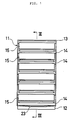
- the multi-stage case for storage of cassettes or cassette blocks are, as shown in Figs. 1 and 2, in which a case housing 11 is made up of a plurality (6 in the illustrated case) of shelf units 14 connected one upon another, between a base unit 12 and a top unit 13, each shelf unit 14 including a drawer 15 and in each drawer 15 a plurality of cassettes 16 are arranged erect (See the lowermost drawer shown in Fig. 3).
- the base unit 12, the top unit 13, the shelf units 14 and the drawers 15 are all integrated molding of synthetic resins such as an ABS resin.
- the base unit 12 is made up of a bottom plate 17 and legs 18 extending downward from each side of the bottom plate 17.
- the front edge of the bottom plate 17 is curved downward in an arc shape to facilitate applying fingers to the inside of a handle 44 of the drawer 15 at the lowermost in pulling out the drawer (See Fig. 1.).
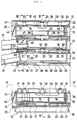
- the top unit 13 is made up of a top plate 24, a front wall 25, a rear wall 26 and side walls 27 extending downward from edges of the top plate and six longitudinal ribs 28 formed in parallel downward from the underside thereof.
- the two (left and right) longitudinal ribs 28 have guide grooves 29 formed between them and the side walls 27 and, as seen from Figs 3 and 4, have three square holes 30.
- the four inside longitudinal ribs 28, as seen from Figs. 3 and 6, have a plurality (two in the illustrated case) of indented stoppers 31 at the lower front ends and between the front and rear ends.
- the shelf unit 14 has U-shaped cross-section and is made up of a shelf board 32 has inverse L-sectioned (left and right) side walls 33 and a rear wall 34.
- the shelf board 32 is, as seen from Figs. 3 and 4, connected with the side walls 33 via drawer guides 35, has access holes 36 about the center for disconnecting the shelf units, has four longitudinal, parallel ribs 37 formed on its underside, as shown in Figs 3 and 6, and on both (left and right) sides of the front end of the topside there are provided recesses 38 for locking the drawer 15, as shown in Figs. 3 and 7.
- the drawer guide 35 like the longitudinal ribs 28 on both (left and right) sides of the aforementioned top unit 13, forms guide grooves 29 between it and the side walls 33, there are provided square holes 30 at three longitudinal positions and the longitudinal ribs 37, like the central (inside) longitudinal ribs 28 extending downward from the aforementioned top unit 13, has indented stoppers 31 at the lower front edge and a plurality (two in the illustrate case) of points between the front and rear ends.
- On the topside of the side (left and right) walls 33 as shown in the aforementioned base unit 12, three pairs of stopping walls 20 with indented stoppers 19 formed at the front end thereof and four pairs of guide walls 21, 22 arranged longitudinally and alternately.
- the base of the stopping walls 20 is formed by cutting off part of the side walls 33 in order to increase the elasticity of the stopping wall 20 (See Fig. 5.).
- the indented stoppers 19 of the stopping walls 20 are formed erect on the base unit 12 and the shelf unit 14 are made freely engageable with and disengageable from the square holes 30 made in the shelf unit 14 or the top unit 12 placed immediately above by the elasticity of the stopping wall 20.
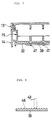
- the drawer 15 is made up of a front wall 40, rear wall 41 and side (left and right) walls 42 extending erect from the bottom plate 39 and its interior is partitioned by partitions 43 into a plurality of spaces.
- a handle is formed before the front wall 40 and on the upper edge of the rear wall 41 there is formed a projection 45 as shown in Fig. 4.
- This projection 45 is formed freely engageable with and disengageable from the indented stopper 31 provided in the underside of shelf unit 14 or the top unit 13 placed immediately above.
- the bottom plate 39 has in its topside, as shown in Figs.
- a continuous longitudinal indentation 46 extending laterally to ensure against sliding of cassettes and also has in the front portion of the underside a plurality (four in the illustrated case) of indented stoppers 47 as shown in Figs. 3 and 7.
- indented stoppers 47 are formed freely engageable with and disengageable from the drawer locking recesses 38 provided in the shelf unit 14 corresponding to the drawer 15.
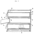
- the case housing 11 is assembled by first putting between the base unit 12 and the top unit 13 a plurality of shelf units 14 and then the stopping walls 20 and guide walls 21, 22 of the base unit 12 and each shelf unit 14 are inserted into the guide grooves 29 formed in the underside of the shelf unit 14 or the top unit 13 immediately above and have each indented stopper 19 of each stopping wall 20 engaged in each square hole 30. Then, the drawer 15 is inserted into each shelf unit 14 with the handle 44 lifted up a little. The projection 45 of the rear wall 41 of the drawer 15 passes under indented stoppers 31 formed in the shelf unit 14 or the top unit 13 immediately above and, as shown in Figs. 3 and 7, the indented stoppers 47 of the drawer 15 are engaged with the recesses 38 for locking of the shelf unit 14 and the drawer 15 is locked thereby.
- the handle 44 of the drawer 15 is lifted a little to disengage the recess 38 for locking the drawer 15 from the indented stopper 47 of the drawer 15, and then the drawer 15 is pulled out halfway (or entirely, if necessary).
- the drawer 15 inclines through its own weight the front end down, the projection 45 of the rear wall 41 engages the indented stoppers 31 of the shelf unit 14 immediately above or the top unit 13 to ensure against further sliding out of the shelf unit 14.
- the cassettes 16 are, as shown in Fig.
- the indentation 46 (See Fig. 8.) formed in the topside of the bottom plate 39 of the drawer 15 are for ensuring against sliding or falling of the cassettes 16 as the drawer 15 is pulled out or pushed in.
- each drawer 15 was made uniform but in other embodiments drawers different in depth can be used in combination so as to enable an increase of the kinds of cassettes that can be stored in a single storage case.
- the present invention consists in putting a plurality of shelf units one upon another separably between the base unit and the top unit, the number of shelf units can be adjusted according to the number of cassettes or cassette blocks to be stored and, moreover, it is possible to use drawers different in depth in combination in a single storage case, this resulting in improved transporting and/or storing efficiency. Also, since the drawer can be pulled out stepwise with the projection formed on the upper edge of its rear wall engaged with a plurality of the indented stoppers provided in the top unit and each shelf unit immediately above, workability is improved with simultaneous increase of the drawer's holding capability to ensure against spontaneous sliding out of the drawer pulled out halfway.
Description
- The present invention relates to a multi-stage storage case for cassettes or cassette blocks according to the preamble part of claim 1.
- Hitherto, this kind of multi-stage storage case was made of a synthetic resin such as ABS resin and, as seen from Figs. 9 and 10, its construction was such that the case housing 1 was made of a plurality (usually 6) of
shelf units 2 and eachshelf unit 2 has housed therein freely slidably adrawer 3, in which cassettes (or cassette blocks) 4 were stored. A pair of (left and right)indented stoppers 6 were formed under the front edge portion of atop unit 5 andshelf units 2, therear wall 7 of eachdrawer 3 has formed thereon a pair of (left and right)projections 8 engageably with and disengageably from theindented stoppers 6 so as to ensure against sliding out of the drawer 3 (See Fig. 10.). - With a conventional multi-stage storage case as described above, there was an inconvenience of necessarily using one whole case even for transportation of a small number of
cassettes 4 for which one or twodrawers 3 suffices. Another problem was that when it suffices to pull outdrawers 3 only partly to take in or take out the wanted number ofcassettes 4, thedrawer 3 partly pulled out inclined with the front end down, this resulting in spontaneous sliding of the drawer with its own weight and that of thecassettes 4 therein and possibly sliding completely out of the case to drop because of the disconnection of theprojections 8 from theindented stoppers 6. - From CH-A-652 012 a multi-stage storage case for cassettes comprising a plurality of shelf units being connected upon another is known. A drawer is slidably disposed in each shelf unit having an engaging hook provided on top of a rear wall of the drawer. The engaging hook can be in brought in engagement with a first rib being provided at the rear end underside the top of the storage case and extending in a direction transversal to the pull out direction of the drawer. A second rib, also extending in the transversal direction is provided at the front end of the top of the storage case for engagement with the engaging hook provided at the rear wall of the drawer. The second transveral rib ensures that the drawer can not fall out unintentionally when pulling the drawer from the storage case.
- From AU-B-573 103, a modular storage cabinet system is known. The system comprises a main sleeve module in form of an open rectangular channel shaped body. Into this main sleeve a main drawer member and an insert drawer may be slidably inserted thereto and removed therefrom. A plurality of main sleeve modules may be interlocked by means of hook clips provided on the side walls of the main sleeve.
- The object of the present invention is to provide a multi-stage storage case with a simply constructed stopper element which ensure the drawers against unintentional falling out.
- This object is solved by a storage case having the features of patent claim 1.
- Preferred embodiments are subject to various dependent claims.
- The invention is described in detail with reference to a preferred embodiment which is shown in the drawings in which
- Fig. 1 is a front view of a multi-stage storage case for cassettes or cassette blocks showing an embodiment of the present invention.
- Fig. 2 is a left side view of the embodiment shown in Fig.1
- Fig. 3 is a sectional view taken along the line III-III of the embodiment shown in Fig. 1 with parts thereof omitted.
- Fig. 4 is a sectional view taken along the line IV-IV of the embodiment shown in Fig. 3 with parts thereof omitted.
- Fig. 5 is an arrow view taken along the line V-V of Fig. 3.
- Fig. 6 is a sectional view taken along the line VI-VI of Fig. 3.
- Fig. 7 is a sectional view taken along the line VII-VII of Fig. 3.
- Fig. 8 is a sectional view taken along the line VIII-VIII of Fig. 5.
- Fig. 9 is a front view of an example of conventional multi-stage storage case for cassettes or cassette blocks.
- Fig.10 is a sectional view taken along the line X-X of Fig.9.
- An embodiment of the present invention will be described below in detail with reference to Figs. 1-8.
- The multi-stage case for storage of cassettes or cassette blocks (hereinafter called cassettes) are, as shown in Figs. 1 and 2, in which a
case housing 11 is made up of a plurality (6 in the illustrated case) ofshelf units 14 connected one upon another, between abase unit 12 and atop unit 13, eachshelf unit 14 including adrawer 15 and in each drawer 15 a plurality ofcassettes 16 are arranged erect (See the lowermost drawer shown in Fig. 3). Thebase unit 12, thetop unit 13, theshelf units 14 and thedrawers 15 are all integrated molding of synthetic resins such as an ABS resin. - As shown in Figs. 3 and 4, the
base unit 12 is made up of abottom plate 17 andlegs 18 extending downward from each side of thebottom plate 17. On both (left and right) sides of the topside of thebottom plate 17, there are provided 3 pairs of stoppingwalls 20 having indentedstoppers 19 at the front ends thereof and 4 pairs ofguide walls bottom plate 17 is curved downward in an arc shape to facilitate applying fingers to the inside of ahandle 44 of thedrawer 15 at the lowermost in pulling out the drawer (See Fig. 1.). - As seen from Figs. 3 and 4, the
top unit 13 is made up of atop plate 24, afront wall 25, arear wall 26 andside walls 27 extending downward from edges of the top plate and sixlongitudinal ribs 28 formed in parallel downward from the underside thereof. Of theseribs 28, as seen from Fig. 4, the two (left and right)longitudinal ribs 28 haveguide grooves 29 formed between them and theside walls 27 and, as seen from Figs 3 and 4, have threesquare holes 30. The four insidelongitudinal ribs 28, as seen from Figs. 3 and 6, have a plurality (two in the illustrated case) ofindented stoppers 31 at the lower front ends and between the front and rear ends. - As seen from Figs. 3 and 4, the
shelf unit 14 has U-shaped cross-section and is made up of ashelf board 32 has inverse L-sectioned (left and right)side walls 33 and arear wall 34. Theshelf board 32 is, as seen from Figs. 3 and 4, connected with theside walls 33 viadrawer guides 35, hasaccess holes 36 about the center for disconnecting the shelf units, has four longitudinal,parallel ribs 37 formed on its underside, as shown in Figs 3 and 6, and on both (left and right) sides of the front end of the topside there are providedrecesses 38 for locking thedrawer 15, as shown in Figs. 3 and 7. - The
drawer guide 35, like thelongitudinal ribs 28 on both (left and right) sides of the aforementionedtop unit 13, formsguide grooves 29 between it and theside walls 33, there are providedsquare holes 30 at three longitudinal positions and thelongitudinal ribs 37, like the central (inside)longitudinal ribs 28 extending downward from the aforementionedtop unit 13, has indentedstoppers 31 at the lower front edge and a plurality (two in the illustrate case) of points between the front and rear ends. On the topside of the side (left and right)walls 33, as shown in Figs. 3-5, there are provided, as in theaforementioned base unit 12, three pairs of stoppingwalls 20 withindented stoppers 19 formed at the front end thereof and four pairs ofguide walls walls 20 is formed by cutting off part of theside walls 33 in order to increase the elasticity of the stopping wall 20 (See Fig. 5.). Theindented stoppers 19 of thestopping walls 20 are formed erect on thebase unit 12 and theshelf unit 14 are made freely engageable with and disengageable from thesquare holes 30 made in theshelf unit 14 or thetop unit 12 placed immediately above by the elasticity of the stoppingwall 20. - As seen from Figs. 3-5, the
drawer 15 is made up of afront wall 40,rear wall 41 and side (left and right)walls 42 extending erect from thebottom plate 39 and its interior is partitioned bypartitions 43 into a plurality of spaces. A handle is formed before thefront wall 40 and on the upper edge of therear wall 41 there is formed aprojection 45 as shown in Fig. 4. Thisprojection 45 is formed freely engageable with and disengageable from theindented stopper 31 provided in the underside ofshelf unit 14 or thetop unit 13 placed immediately above. Thebottom plate 39 has in its topside, as shown in Figs. 5 and 8, a continuouslongitudinal indentation 46 extending laterally to ensure against sliding of cassettes and also has in the front portion of the underside a plurality (four in the illustrated case) ofindented stoppers 47 as shown in Figs. 3 and 7. These indentedstoppers 47 are formed freely engageable with and disengageable from thedrawer locking recesses 38 provided in theshelf unit 14 corresponding to thedrawer 15. - The
cassettes 16, when they are stored in thedrawer 15 erect, as shown in Fig. 3, the necessary matters such as name and date can be written on the top side thereof. - In assembling the multi-stage storage case of the construction as described above, first, as shown in Figs. 3, 4 and 6, the
case housing 11 is assembled by first putting between thebase unit 12 and the top unit 13 a plurality ofshelf units 14 and then thestopping walls 20 andguide walls base unit 12 and eachshelf unit 14 are inserted into theguide grooves 29 formed in the underside of theshelf unit 14 or thetop unit 13 immediately above and have each indentedstopper 19 of each stoppingwall 20 engaged in eachsquare hole 30. Then, thedrawer 15 is inserted into eachshelf unit 14 with thehandle 44 lifted up a little. Theprojection 45 of therear wall 41 of thedrawer 15 passes underindented stoppers 31 formed in theshelf unit 14 or thetop unit 13 immediately above and, as shown in Figs. 3 and 7, theindented stoppers 47 of thedrawer 15 are engaged with therecesses 38 for locking of theshelf unit 14 and thedrawer 15 is locked thereby. - In order to put the
cassettes 16 into thedrawer 15 of the multi-stage storage case thus assembled, first thehandle 44 of thedrawer 15 is lifted a little to disengage therecess 38 for locking thedrawer 15 from theindented stopper 47 of thedrawer 15, and then thedrawer 15 is pulled out halfway (or entirely, if necessary). As shown in Figs. 3 and 6, thedrawer 15 inclines through its own weight the front end down, theprojection 45 of therear wall 41 engages theindented stoppers 31 of theshelf unit 14 immediately above or thetop unit 13 to ensure against further sliding out of theshelf unit 14. Thecassettes 16 are, as shown in Fig. 3, stored in the drawer arranged erect, with the side in which the referring index is written facing up, to make it easily visible and the drawer is then pushed in. The procedure is essentially the same when the cassettes are taken out of thedrawer 15. The indentation 46 (See Fig. 8.) formed in the topside of thebottom plate 39 of thedrawer 15 are for ensuring against sliding or falling of thecassettes 16 as thedrawer 15 is pulled out or pushed in. - In disassembling the storage case into the
base unit 12, thetop unit 13 and andshelf units 14, all or part of thedrawers 15 are pulled out, and then, with a hand inserted through the front opening of theshelf unit 14 and working with fingers through theaccess hole 36 to disengage theindented stoppers 19 of thestopping walls 20 of thebase unit 12 or theshelf unit 14 from thesquare holes 30 in theshelf unit 14 or thetop unit 13 for separation of thebase unit 12, thetop unit 13 or eachshelf unit 14. It is thus possible to adjust the number of theshelf units 14 according to the number ofcassettes 16 to be stored or disassemble a multi-stage storage case as a whole. - Although in this embodiment the depth of each
drawer 15 was made uniform but in other embodiments drawers different in depth can be used in combination so as to enable an increase of the kinds of cassettes that can be stored in a single storage case. - Since, as described above, the present invention consists in putting a plurality of shelf units one upon another separably between the base unit and the top unit, the number of shelf units can be adjusted according to the number of cassettes or cassette blocks to be stored and, moreover, it is possible to use drawers different in depth in combination in a single storage case, this resulting in improved transporting and/or storing efficiency. Also, since the drawer can be pulled out stepwise with the projection formed on the upper edge of its rear wall engaged with a plurality of the indented stoppers provided in the top unit and each shelf unit immediately above, workability is improved with simultaneous increase of the drawer's holding capability to ensure against spontaneous sliding out of the drawer pulled out halfway.
- It is also possible to prevent spontaneous sliding of drawers out of the case due to inclination of storage case since each drawer is locked in the closed state with the indented stopper provided in the drawer engaged with the locking recess provided in the shelf unit.
- Further, by providing anti-sliding indentation in the topside of the bottom plate of the drawer it is possible to ensure against sliding or falling of cassettes or cassette blocks arranged erect in the drawer as it is pulled out or pushed in.
Claims (3)
- A multi-stage storage case for cassettes or cassette blocks comprising a plurality of U-sectioned shelf units (14) being connected one upon another, a drawer (15) for cassettes or cassette blocks being slidably disposed in each shelf unit (14), an upward projection (45) on top of a rear wall (41) of said drawer (15) which can be brought in engagement with a stopping means when said drawer (15) is pulled out, characterized in that said shelf units (14) are disconnectably connected between a base unit (12) and a top unit (13) and in that said stopping means comprises a plurality of first indented stoppers (31) being formed along the pulling direction in the underside of said top unit (13) and each shelf unit (14).
- The multi-stage storage case according to claim 1, characterized by recesses (38) for locking each drawer (15) are provided in the upper front edge portion of each shelf unit (14), and a plurality of second indented stoppers (47) are provided in the lower front edge portion of each drawer (15) engageable with and disengageable from said recesses (38) to thereby lock said drawer (15) in the closed position.
- The multi-stage storage case according to claim 1 or 2, characterized by a continuous indentation (46) being formed in the topside of a bottom plate (39) of said drawer (15) to ensure against sliding of cassettes or cassette blocks.
Applications Claiming Priority (2)
| Application Number | Priority Date | Filing Date | Title |
|---|---|---|---|
| JP1991091433U JP2604446Y2 (en) | 1991-10-11 | 1991-10-11 | Multistage storage case for cassette or cassette block |
| JP91433/91 | 1991-10-11 |
Publications (2)
| Publication Number | Publication Date |
|---|---|
| EP0536785A1 EP0536785A1 (en) | 1993-04-14 |
| EP0536785B1 true EP0536785B1 (en) | 1996-04-03 |
Family
ID=14026236
Family Applications (1)
| Application Number | Title | Priority Date | Filing Date |
|---|---|---|---|
| EP92117316A Expired - Lifetime EP0536785B1 (en) | 1991-10-11 | 1992-10-09 | Multi-stage storage case for cassettes or cassette blocks |
Country Status (7)
| Country | Link |
|---|---|
| US (1) | US5399006A (en) |
| EP (1) | EP0536785B1 (en) |
| JP (1) | JP2604446Y2 (en) |
| KR (1) | KR0128725Y1 (en) |
| AU (1) | AU662016B2 (en) |
| CA (1) | CA2080262C (en) |
| DE (1) | DE69209608T2 (en) |
Families Citing this family (18)
| Publication number | Priority date | Publication date | Assignee | Title |
|---|---|---|---|---|
| US5597216A (en) * | 1995-11-06 | 1997-01-28 | Real; Frank | Multi-media storage drawer assembly |
| US5913580A (en) * | 1997-05-30 | 1999-06-22 | Liu; Ching-Rong | Structure of drawer type storage bin |
| ATA137597A (en) * | 1997-08-18 | 2000-09-15 | Condor Ledermode | CASSETTE FOR STORING AND PRESENTING ITEMS |
| DE19954965A1 (en) * | 1999-11-16 | 2001-05-31 | Kempa Hans Dieter | Cupboard has bearer rails attached to its walls with guide rails between them, bearer rails having downwardly-sloping section at top of one side and retaining section formed by diagonally opposite corner to retain trays inserted into system |
| KR101099353B1 (en) * | 2005-01-25 | 2011-12-26 | 엘지전자 주식회사 | Detergent box assembly of drum type washer |
| CN100546520C (en) * | 2005-03-15 | 2009-10-07 | 冷鹭浩 | A kind of combined filing cabinet |
| GB2442935B (en) * | 2006-10-20 | 2009-10-28 | Certwood Ltd | Storage tray system |
| DE102010008523B4 (en) * | 2010-02-18 | 2012-05-03 | Albrecht Blum | Containers for food |
| JP5338833B2 (en) * | 2011-03-23 | 2013-11-13 | ブラザー工業株式会社 | Image forming apparatus |
| JP5980026B2 (en) * | 2012-07-18 | 2016-08-31 | キヤノン株式会社 | Sheet feeding apparatus and image forming apparatus |
| CA2988701C (en) * | 2015-07-24 | 2023-05-16 | Tts Tooltechnic Systems Ag & Co. Kg | Storage container |
| US10524587B2 (en) * | 2016-08-17 | 2020-01-07 | The Hillman Group, Inc. | Cabinet with telescoping trays for fastener bins |
| USD866224S1 (en) * | 2018-01-24 | 2019-11-12 | Rh Us, Llc | Nightstand |
| CN108725932A (en) * | 2018-04-30 | 2018-11-02 | 王大军 | A kind of logistics distribution transport case |
| CN109335238B (en) * | 2018-10-30 | 2020-04-21 | 温州圆拓机械科技有限公司 | Storage device is collected with convenient sample to food detection |
| CN110882065B (en) * | 2019-12-03 | 2022-08-02 | 海晏县哈勒景乡畜牧兽医站 | Multifunctional tool box for livestock raising and veterinary use |
| CN112874994B (en) * | 2021-01-14 | 2022-10-25 | 济南高更食品科技有限公司 | Packing box |
| US11844430B2 (en) * | 2021-04-09 | 2023-12-19 | Advantus, Corp. | Configurable literature organizer |
Family Cites Families (12)
| Publication number | Priority date | Publication date | Assignee | Title |
|---|---|---|---|---|
| US1774237A (en) * | 1922-07-06 | 1930-08-26 | Remington Rand Inc | Index or record cabinet and the like |
| US3722975A (en) * | 1972-01-03 | 1973-03-27 | Rubbermaid Inc | Tilt-open drawer construction |
| FR2223948A5 (en) * | 1973-03-29 | 1974-10-25 | Sicopal | |
| US3888350A (en) * | 1974-05-10 | 1975-06-10 | William Horvath | Safety container |
| CH652012A5 (en) * | 1981-01-22 | 1985-10-31 | Plaston Ag | Stackable filing container with pull-out drawer |
| JPS5926032A (en) * | 1982-01-12 | 1984-02-10 | インバレスク・リサ−チ・インタ−ナシヨナル・リミテツド | Cassette of biological tissue |
| AU573103B2 (en) * | 1985-10-08 | 1988-05-26 | Webber, B.J. | Stackable filing modules |
| JPH01177984U (en) * | 1988-05-30 | 1989-12-20 | ||
| US4892368A (en) * | 1988-10-03 | 1990-01-09 | Malgo Corporation | Drawer slide |
| DE8902390U1 (en) * | 1989-03-01 | 1989-07-06 | Klinotec Gmbh Medizinisch-Technische Artikel, 7518 Bretten, De | |
| JPH0716345Y2 (en) * | 1988-12-07 | 1995-04-19 | 大日本インキ化学工業株式会社 | Drawer container |
| JP3078868U (en) * | 1999-12-29 | 2001-07-27 | 博一 北野 | Simple packing device for raw and boiled eggs using recycled paper and recycled paper |
-
1991
- 1991-10-11 JP JP1991091433U patent/JP2604446Y2/en not_active Expired - Lifetime
-
1992
- 1992-10-06 AU AU26208/92A patent/AU662016B2/en not_active Ceased
- 1992-10-09 EP EP92117316A patent/EP0536785B1/en not_active Expired - Lifetime
- 1992-10-09 DE DE69209608T patent/DE69209608T2/en not_active Expired - Fee Related
- 1992-10-09 CA CA002080262A patent/CA2080262C/en not_active Expired - Fee Related
- 1992-10-09 KR KR2019920019435U patent/KR0128725Y1/en not_active IP Right Cessation
-
1994
- 1994-08-15 US US08/290,120 patent/US5399006A/en not_active Expired - Lifetime
Also Published As
| Publication number | Publication date |
|---|---|
| AU2620892A (en) | 1993-04-22 |
| KR930008107U (en) | 1993-05-24 |
| EP0536785A1 (en) | 1993-04-14 |
| KR0128725Y1 (en) | 1998-11-02 |
| JPH0533059U (en) | 1993-04-30 |
| JP2604446Y2 (en) | 2000-05-15 |
| US5399006A (en) | 1995-03-21 |
| DE69209608T2 (en) | 1996-08-22 |
| CA2080262C (en) | 2000-08-01 |
| AU662016B2 (en) | 1995-08-17 |
| CA2080262A1 (en) | 1993-04-12 |
| DE69209608D1 (en) | 1996-05-09 |
Similar Documents
| Publication | Publication Date | Title |
|---|---|---|
| EP0536785B1 (en) | Multi-stage storage case for cassettes or cassette blocks | |
| US5664856A (en) | Stackable divided drawer partition | |
| AU707376B2 (en) | Display unit | |
| US5887715A (en) | Tool case with snap-in modules | |
| KR100393315B1 (en) | cabinet | |
| US8708436B2 (en) | Arrangement of telescopic extensions | |
| US3975071A (en) | File cabinet construction | |
| US20030011291A1 (en) | Storage bin mounting system for a refrigerator door | |
| CA2099352A1 (en) | Tool container | |
| EP0510942B1 (en) | Adjustable tray | |
| US4401350A (en) | Modular storage system | |
| US4389078A (en) | Modular storage unit | |
| US4436355A (en) | Modular storage system | |
| US4909398A (en) | Magazine file system | |
| CA2234372C (en) | Tool case with externally-accessible compartments | |
| US5358321A (en) | Modular multi-media cabinet | |
| KR20050108319A (en) | Tablet case | |
| USRE34171E (en) | Medication carts and cassettes | |
| US4178049A (en) | Shelf box with dual pivoting stop mechanism | |
| US6196647B1 (en) | Vertical media storage system | |
| US6203129B1 (en) | Vertical media storage system | |
| GB2194510A (en) | Storage containers | |
| US4076352A (en) | Sliding drawer | |
| CA2303551C (en) | Tool case with snap-in modules | |
| US4616892A (en) | Plastic Drawer |
Legal Events
| Date | Code | Title | Description |
|---|---|---|---|
| PUAI | Public reference made under article 153(3) epc to a published international application that has entered the european phase |
Free format text: ORIGINAL CODE: 0009012 |
|
| AK | Designated contracting states |
Kind code of ref document: A1 Designated state(s): CH DE FR GB LI SE |
|
| 17P | Request for examination filed |
Effective date: 19930722 |
|
| 17Q | First examination report despatched |
Effective date: 19941107 |
|
| GRAH | Despatch of communication of intention to grant a patent |
Free format text: ORIGINAL CODE: EPIDOS IGRA |
|
| GRAA | (expected) grant |
Free format text: ORIGINAL CODE: 0009210 |
|
| AK | Designated contracting states |
Kind code of ref document: B1 Designated state(s): CH DE FR GB LI SE |
|
| REG | Reference to a national code |
Ref country code: CH Ref legal event code: NV Representative=s name: PATENTANWALTSBUERO JEAN HUNZIKER |
|
| REF | Corresponds to: |
Ref document number: 69209608 Country of ref document: DE Date of ref document: 19960509 |
|
| ET | Fr: translation filed | ||
| PLBE | No opposition filed within time limit |
Free format text: ORIGINAL CODE: 0009261 |
|
| STAA | Information on the status of an ep patent application or granted ep patent |
Free format text: STATUS: NO OPPOSITION FILED WITHIN TIME LIMIT |
|
| 26N | No opposition filed | ||
| REG | Reference to a national code |
Ref country code: GB Ref legal event code: IF02 |
|
| PGFP | Annual fee paid to national office [announced via postgrant information from national office to epo] |
Ref country code: FR Payment date: 20061020 Year of fee payment: 15 |
|
| PGFP | Annual fee paid to national office [announced via postgrant information from national office to epo] |
Ref country code: CH Payment date: 20061024 Year of fee payment: 15 Ref country code: SE Payment date: 20061024 Year of fee payment: 15 |
|
| PGFP | Annual fee paid to national office [announced via postgrant information from national office to epo] |
Ref country code: GB Payment date: 20061027 Year of fee payment: 15 |
|
| PGFP | Annual fee paid to national office [announced via postgrant information from national office to epo] |
Ref country code: DE Payment date: 20061129 Year of fee payment: 15 |
|
| EUG | Se: european patent has lapsed | ||
| GBPC | Gb: european patent ceased through non-payment of renewal fee |
Effective date: 20071009 |
|
| REG | Reference to a national code |
Ref country code: CH Ref legal event code: PL |
|
| PG25 | Lapsed in a contracting state [announced via postgrant information from national office to epo] |
Ref country code: DE Free format text: LAPSE BECAUSE OF NON-PAYMENT OF DUE FEES Effective date: 20080501 Ref country code: CH Free format text: LAPSE BECAUSE OF NON-PAYMENT OF DUE FEES Effective date: 20071031 Ref country code: LI Free format text: LAPSE BECAUSE OF NON-PAYMENT OF DUE FEES Effective date: 20071031 |
|
| REG | Reference to a national code |
Ref country code: FR Ref legal event code: ST Effective date: 20080630 |
|
| PG25 | Lapsed in a contracting state [announced via postgrant information from national office to epo] |
Ref country code: SE Free format text: LAPSE BECAUSE OF NON-PAYMENT OF DUE FEES Effective date: 20071010 |
|
| PG25 | Lapsed in a contracting state [announced via postgrant information from national office to epo] |
Ref country code: GB Free format text: LAPSE BECAUSE OF NON-PAYMENT OF DUE FEES Effective date: 20071009 |
|
| PG25 | Lapsed in a contracting state [announced via postgrant information from national office to epo] |
Ref country code: FR Free format text: LAPSE BECAUSE OF NON-PAYMENT OF DUE FEES Effective date: 20071031 |