EP0536639B1 - Braking system for lorries with service brake and retarder - Google Patents
Braking system for lorries with service brake and retarder Download PDFInfo
- Publication number
- EP0536639B1 EP0536639B1 EP92116813A EP92116813A EP0536639B1 EP 0536639 B1 EP0536639 B1 EP 0536639B1 EP 92116813 A EP92116813 A EP 92116813A EP 92116813 A EP92116813 A EP 92116813A EP 0536639 B1 EP0536639 B1 EP 0536639B1
- Authority
- EP
- European Patent Office
- Prior art keywords
- retarder
- braking
- brake
- braking system
- stages
- Prior art date
- Legal status (The legal status is an assumption and is not a legal conclusion. Google has not performed a legal analysis and makes no representation as to the accuracy of the status listed.)
- Expired - Lifetime
Links
Images

Classifications
-
- B—PERFORMING OPERATIONS; TRANSPORTING
- B60—VEHICLES IN GENERAL
- B60T—VEHICLE BRAKE CONTROL SYSTEMS OR PARTS THEREOF; BRAKE CONTROL SYSTEMS OR PARTS THEREOF, IN GENERAL; ARRANGEMENT OF BRAKING ELEMENTS ON VEHICLES IN GENERAL; PORTABLE DEVICES FOR PREVENTING UNWANTED MOVEMENT OF VEHICLES; VEHICLE MODIFICATIONS TO FACILITATE COOLING OF BRAKES
- B60T13/00—Transmitting braking action from initiating means to ultimate brake actuator with power assistance or drive; Brake systems incorporating such transmitting means, e.g. air-pressure brake systems
- B60T13/10—Transmitting braking action from initiating means to ultimate brake actuator with power assistance or drive; Brake systems incorporating such transmitting means, e.g. air-pressure brake systems with fluid assistance, drive, or release
- B60T13/58—Combined or convertible systems
- B60T13/585—Combined or convertible systems comprising friction brakes and retarders
-
- B—PERFORMING OPERATIONS; TRANSPORTING
- B60—VEHICLES IN GENERAL
- B60T—VEHICLE BRAKE CONTROL SYSTEMS OR PARTS THEREOF; BRAKE CONTROL SYSTEMS OR PARTS THEREOF, IN GENERAL; ARRANGEMENT OF BRAKING ELEMENTS ON VEHICLES IN GENERAL; PORTABLE DEVICES FOR PREVENTING UNWANTED MOVEMENT OF VEHICLES; VEHICLE MODIFICATIONS TO FACILITATE COOLING OF BRAKES
- B60T1/00—Arrangements of braking elements, i.e. of those parts where braking effect occurs specially for vehicles
- B60T1/02—Arrangements of braking elements, i.e. of those parts where braking effect occurs specially for vehicles acting by retarding wheels
- B60T1/08—Arrangements of braking elements, i.e. of those parts where braking effect occurs specially for vehicles acting by retarding wheels using fluid or powdered medium
-
- B—PERFORMING OPERATIONS; TRANSPORTING
- B60—VEHICLES IN GENERAL
- B60T—VEHICLE BRAKE CONTROL SYSTEMS OR PARTS THEREOF; BRAKE CONTROL SYSTEMS OR PARTS THEREOF, IN GENERAL; ARRANGEMENT OF BRAKING ELEMENTS ON VEHICLES IN GENERAL; PORTABLE DEVICES FOR PREVENTING UNWANTED MOVEMENT OF VEHICLES; VEHICLE MODIFICATIONS TO FACILITATE COOLING OF BRAKES
- B60T8/00—Arrangements for adjusting wheel-braking force to meet varying vehicular or ground-surface conditions, e.g. limiting or varying distribution of braking force
- B60T8/18—Arrangements for adjusting wheel-braking force to meet varying vehicular or ground-surface conditions, e.g. limiting or varying distribution of braking force responsive to vehicle weight or load, e.g. load distribution
Definitions
- the invention relates to a brake system for commercial vehicles with a service brake and a continuous brake according to the preamble of claim 1.
- Known brake systems for commercial vehicles with service and continuous brakes provide linear, parallel-connected retarders which have several braking stages with progressive grading, especially when the vehicle is unladen.
- the rough grading leads to a disadvantageous retarder effect with jerky deceleration of the vehicle when braking, especially when the vehicle is unladen.
- the retarder cannot be connected upstream to the service brake.
- the upper braking stages of the retarder can be switched off. It is switched off by means of a cam switch.
- an additional mechanical lever switch of comparatively complicated construction is used, which is also cost-intensive.
- the known upper braking stages can be switched off progressively when larger deflection values of the control lever are exceeded, and the electrical control device has a shutdown relay for the braking stage of the retarder to be deactivated.
- a brake system of the type mentioned which uses a pressure control valve with several pressure relief valves to control the pressure in the retarder.
- the known brake system is comparatively complicated and only suitable in connection with a hydrodynamic converter.
- the object of the invention is to provide a brake system of the type mentioned which, with the aid of simple means, enables substantially jerk-free braking operation of leaf-sprung commercial vehicles even when the vehicle is partially or unloaded.
- the essence of the invention is the creation of an electrical switch-off device for the upper braking stages of a multi-stage retarder, in particular in the case of partially or unloaded vehicles with leaf-sprung rear axles and vehicle-fixed, automatically load-dependent brake control valves.
- the deflection position of the control lever of the (already existing) ALB controller is determined by the electrical control device with an inductive sensor within certain, predefinable limits and a corresponding electrical switch-off signal is triggered which actuates individual switch-off relays which switch off the upper braking stages of the multi-stage brake-operated retarder. This means that a brake-operated retarder does not develop the full braking force when the vehicle is empty or only partially loaded.
- an essentially jerk-free braking operation is set up. This not only improves the driving comfort of the commercial vehicle, but also increases driving safety due to the absence of jerks.
- the (geometric) grading of the retarder is expediently selected. If an electric or hydraulic retarder is switched in six stages, the delay effect of the stages with the percentages 12.5 / 25 / 37.5 / 50/75/100% can be used, for example. Other distributions can also result from optimization.
- the invention therefore overcomes the essential disadvantage of known braking systems, which is seen in the fact that the retarder effect overlaps the service braking effect is and this results in an undesirable progressivity of the braking effect, especially in the area of small decelerations.
- the retarder effect can be reduced when the vehicle is empty (if necessary also with partial load) so that not all stages are used, but only the first four braking stages, for example , which reduces the maximum retarder braking effect to approx. 50% or the like. corresponds.
- This can be achieved either by connecting the sensors directly to the brake pressure of the rear axle reduced by the ALB, or by manipulating the electronics if the retarder is controlled by a potentiometer located in the motor vehicle brake valve.
- the retarder can also be stepped up or down steplessly by means of a potentiometer in the motor vehicle brake valve.
- the limitation of the maximum effect is also possible here by appropriate intervention in the control electronics.
- DE-OS 2 023 880 discloses a braking system for commercial vehicles with service and continuous braking in the form of a retarder, which is regulated as a function of the load on the vehicle.
- a retarder which is regulated as a function of the load on the vehicle.
- the vehicle must have air-sprung axles.
- the brake system is generally not suitable for leaf-sprung axles. Otherwise, the known retarder cannot be switched off in its upper braking stages, as is the case with the generic braking system.
- the invention proposes (similarly to EP 0 361 708 A2) in a further development a brake system with an electronically controlled brake system, in which the braking deceleration is preferably predetermined by actuating the brake pedal becomes.
- a brake system 1 for the leaf-sprung rear axle 10 of a commercial vehicle basically provides a vehicle-mounted, automatically load-dependent brake control valve, a so-called ALB controller 3, the controller lever 4 of which is connected via a linkage (not shown), e.g. is connected to the sensor rod between the first and second rear axles 10 of a double axle assembly.
- the control lever 3 is more or less deflected in its swivel position.
- the pressure output 7 of the ALB controller 3 is connected to the brake cylinders of the rear axle 10 via a brake line 12.
- a reduced braking pressure is thus applied to the rear axle 10.
- the brake line 12 or the pressure output 7 of the ALB controller 3 is also connected via a pressure switch control 8 to the individual brake stages R1, R2, ... R6, with each brake stage being assigned a pressure switch 13 with different pressure switching characteristics.
- the retarder is therefore increasingly put into operation with increasing brake pressure.
- the retarder effect can be reduced when the vehicle is empty (if necessary also with partial load) so that not all stages are used, but rather, for example, according to the variant of FIG. 1 the last two retarder brake stages R5, R6 are switched off. It is switched off by an electrical control device 2 with an inductive sensor 5, which can be actuated as a function of the deflection position of the regulator lever 4 of the ALB regulator 3. Electrical switch-off signals actuate in particular the switch-off relay 6 of the fifth and / or the sixth braking stage R5, R6 of the retarder.
- Switching off takes place, for example, at a rear axle load of 25 to 50% of the maximum load if six retarder braking levels are provided.
- retarders that have only four switching stages, for example with electric retarders or eddy current brakes, either the last, i.e. the fourth stage or the last two, i.e. the third and fourth stages are switched off.
- the inductive sensor 5 can also be a different type of sensor. It does not necessarily have to lie in the area of the control lever 4, but can also act on an adjacent linkage which is pre-coupled to the control lever 4.
- the arrangement of a sensor on the sensor rod between the first and second rear axles of a double-axle unit is also conceivable.
- the embodiment variant according to FIGS. 2 and 3 provides an electrical control device 2 for switching off the upper braking stages R5, R6 as in the embodiment of FIG. 1.
- the pressure switch control 8 to start up the individual brake levels R1, R2 ... the retarder directly connected to the output of a motor vehicle brake valve 11.
- the retarder of the service brake can be continuously switched on or off using a potentiometer in the motor vehicle brake valve.
- the limitation of the maximum effect is possible by appropriate intervention in the control electronics.
Landscapes
- Engineering & Computer Science (AREA)
- Transportation (AREA)
- Mechanical Engineering (AREA)
- Regulating Braking Force (AREA)
- Hydraulic Control Valves For Brake Systems (AREA)
Description
Die Erfindung betrifft eine Bremsanlage für Nutzkraftwagen mit einer Betriebsbremse und einer Dauerbremse gemäß Oberbegriff des Anspruchs 1.The invention relates to a brake system for commercial vehicles with a service brake and a continuous brake according to the preamble of
Bekannte Bremsanlagen für Nutzkraftwagen mit Betriebs- und Dauerbremse sehen linear parallelgeschaltete Retarder vor, welche mehrere Bremsstufen mit progressiver Stufung insbesondere bei unbeladenem Fahrzeug besitzen. Die grobe Stufung führt gerade bei unbeladenem Fahrzeug zu einer nachteiligen Retarderwirkung mit ruckbehafteter Verzögerung des Fahrzeugs bei einem Bremsen. Der Retarder kann zur Betriebsbremse nicht vorgeschaltet werden.Known brake systems for commercial vehicles with service and continuous brakes provide linear, parallel-connected retarders which have several braking stages with progressive grading, especially when the vehicle is unladen. The rough grading leads to a disadvantageous retarder effect with jerky deceleration of the vehicle when braking, especially when the vehicle is unladen. The retarder cannot be connected upstream to the service brake.
Gemäß FR-A-2 312 389 sind die oberen Bremsstufen des Retarders abschaltbar. Die Abschaltung erfolgt mittels Nockenschalter. Bei der bekannten, eingangs genannten Bremsanlage gemäß FR-A-2 312 389 wird ein zusätzlicher mechanischer Hebelschalter vergleichsweise komplizierten Aufbaus verwendet, welcher zudem kostenintentiv ist. Gleichwohl sind die bekannten oberen Bremsstufen fortschreitend bei der Überschreitung von jeweils größeren Auslenkwerten des Reglerhebels abschaltbar, und es besitzt die elektrische Steuereinrichtung jeweils ein Abschaltrelais für die abzuschaltende Bremsstufe des Retarders.According to FR-A-2 312 389, the upper braking stages of the retarder can be switched off. It is switched off by means of a cam switch. In the known brake system according to FR-A-2 312 389 mentioned at the outset, an additional mechanical lever switch of comparatively complicated construction is used, which is also cost-intensive. Nevertheless, the known upper braking stages can be switched off progressively when larger deflection values of the control lever are exceeded, and the electrical control device has a shutdown relay for the braking stage of the retarder to be deactivated.
Aus DE-AS 26 52 651 ist eine Bremsanlage der eingangs genannten Art bekannt, welche zur Steuerung des Druckes im Retarder ein Druckregelventil mit mehreren Überdruckventilen verwendet. Die bekannte Bremsanlage ist jedoch vergleichsweise kompliziert aufgebaut und nur in Verbindung mit einem hydrodynamischen Wandler geeignet.From DE-AS 26 52 651 a brake system of the type mentioned is known which uses a pressure control valve with several pressure relief valves to control the pressure in the retarder. However, the known brake system is comparatively complicated and only suitable in connection with a hydrodynamic converter.
Aufgabe der Erfindung ist die Schaffung einer Bremsanlage der eingangs genannten Art, welche mit Hilfe einfacher Mittel einen im wesentlichen ruckfreien Bremsbetrieb von blattgefederten Nutzkraftwagen auch im teil- oder unbeladenem Zustand des Fahrzeugs ermöglicht.The object of the invention is to provide a brake system of the type mentioned which, with the aid of simple means, enables substantially jerk-free braking operation of leaf-sprung commercial vehicles even when the vehicle is partially or unloaded.
Gelöst wird die der Erfindung zugrundeliegende Aufgabe durch die im kennzeichnenden Teil des Anspruchs 1 angegebenen Merkmale.The object on which the invention is based is achieved by the features specified in the characterizing part of
Vorteilhaft weitergebildet wird der Erfindungsgegenstand durch die Merkmale der Unteransprüche 2 bis 7.The subject of the invention is advantageously further developed by the features of
Wesen der Erfindung ist die Schaffung einer elektrischen Abschalteinrichtung für die oberen Bremsstufen eines mehrstufigen Retarders insbesondere bei teil- oder unbeladenem Fahrzeug mit blattgefederter Hinterachse und fahrzeugfestem automatisch lastabhängigen Bremsregelventil. Hierbei wird die Auslenkstellung des Reglerhebels des (ohnehin vorhandenen) ALB-Reglers durch die elektrische Steuereinrichtung mit einem Induktivsensor innerhalb bestimmter, vorgebbarer Grenzen festgestellt und ein entsprechendes elektrisches Abschaltsignal ausgelöst, welches einzelne Abschaltrelais betätigt, die die oberen Bremsstufen des mehrstufigen bremsbetriebenen Retarders abschalten. Damit entfaltet ein bremsbetriebener Retarder bei leerem oder nur teilbeladenem Fahrzeug nicht die volle Bremskraft. Entsprechend der Feinabstufung des Retarders und der Zahl der abschaltbaren Bremsstufenwird mithin ein im wesentlichen ruckfreier Bremsbetrieb eingerichtet. Es ergibt sich nicht nur ein verbesserter Fahrkomfort des Nutzfahrzeugs, sondern auch aufgrund der Ruckfreiheit eine erhöhte Fahrsicherheit.The essence of the invention is the creation of an electrical switch-off device for the upper braking stages of a multi-stage retarder, in particular in the case of partially or unloaded vehicles with leaf-sprung rear axles and vehicle-fixed, automatically load-dependent brake control valves. The deflection position of the control lever of the (already existing) ALB controller is determined by the electrical control device with an inductive sensor within certain, predefinable limits and a corresponding electrical switch-off signal is triggered which actuates individual switch-off relays which switch off the upper braking stages of the multi-stage brake-operated retarder. This means that a brake-operated retarder does not develop the full braking force when the vehicle is empty or only partially loaded. In accordance with the fine grading of the retarder and the number of brake stages that can be deactivated, an essentially jerk-free braking operation is set up. This not only improves the driving comfort of the commercial vehicle, but also increases driving safety due to the absence of jerks.
Zweckmäßigerweise wird die (geometrische) Stufung des Retarders feingewählt. Wird ein elektrischer oder hydraulischer Retarder in sechs Stufen geschaltet, kann beispielsweise die Verzögerungswirkung der Stufen mit den Prozentsätzen 12,5/25/37,5/50/75/100 % einsetzen. Auch andere Verteilungen können sich durch Optimierung ergeben.The (geometric) grading of the retarder is expediently selected. If an electric or hydraulic retarder is switched in six stages, the delay effect of the stages with the percentages 12.5 / 25 / 37.5 / 50/75/100% can be used, for example. Other distributions can also result from optimization.
Durch die Erfindung wird mithin der wesentliche Nachteil bekannter Bremssysteme überwunden, der darin gesehen wird, daß die Retarderwirkung der Betriebsbremswirkung überlagert wird und sich hierdurch eine ungewünschte Progressivität der Bremswirkung insbesondere im Bereich geringer Verzögerungen ergibt.The invention therefore overcomes the essential disadvantage of known braking systems, which is seen in the fact that the retarder effect overlaps the service braking effect is and this results in an undesirable progressivity of the braking effect, especially in the area of small decelerations.
Um auch bei leerem Fahrzeug die unerwünschten Verzögerungsrucke zu vermeiden bzw. kaum spürbar werden zu lassen, kann die Retarderwirkung bei leerem Fahrzeug (erforderlichenfalls auch bei Teilbeladung) derart reduziert werden, daß nicht mehr alle Stufen zum Einsatz kommen, sondern beispielsweise nur die ersten vier Bremsstufen, was eine Reduzierung der maximalen Retarderbremswirkung auf ca. 50% o.ä. entspricht. Dies kann entweder erzielt werden durch Anschluß der Sensoren direkt an dem durch den ALB reduzierten Bremsdruck der Hinterachse, oder durch Manipulation der Elektronik, falls der Retarder von einem im Motorwagenbremsventil befindlichen Potentiometer gesteuert wird.In order to avoid the undesirable deceleration jerks even when the vehicle is empty, or to make them hardly noticeable, the retarder effect can be reduced when the vehicle is empty (if necessary also with partial load) so that not all stages are used, but only the first four braking stages, for example , which reduces the maximum retarder braking effect to approx. 50% or the like. corresponds. This can be achieved either by connecting the sensors directly to the brake pressure of the rear axle reduced by the ALB, or by manipulating the electronics if the retarder is controlled by a potentiometer located in the motor vehicle brake valve.
Eine weitere Besonderheit der Erfindung liegt darin, daß der Retarder durch ein Potentiometer im Motorwagenbremsventil auch stufenlos vor- bzw. zugeschaltet werden kann. Die Begrenzung des Wirkungsmaximums ist auch hier durch entsprechenden Eingriff in die Steuerelektronik möglich.Another peculiarity of the invention is that the retarder can also be stepped up or down steplessly by means of a potentiometer in the motor vehicle brake valve. The limitation of the maximum effect is also possible here by appropriate intervention in the control electronics.
Am Rande sei bemerkt, daß eine eventuelle Überbremsung der Hinterachse insofern bedeutungslos ist, als der Retarder auch von einem ABS-System überwacht und in seiner Wirkung geregelt werden kann.In passing it should be noted that a possible overbraking of the rear axle is insignificant insofar as the retarder can also be monitored by an ABS system and its effect can be regulated.
Zwar ist aus DE-OS 2 023 880 eine Bremsanlage für Nutzkraftwagen mit Betriebs- und Dauerbremse in Form eines Retarders bekannt, der in Abhängigkeit von der Beladung des Fahrzeugs geregelt wird. Das Fahrzeug muß jedoch luftgefederte Achsen besitzen. Für blattgefederte Achsen ist die Bremsanlage grundsätzlich nicht geeignet. Im übrigen ist der bekannte Retarder nicht in seinen oberen Bremsstufen abschaltbar, wie dies bei der gattungsgemäßen Bremsanlage der Fall ist.DE-OS 2 023 880 discloses a braking system for commercial vehicles with service and continuous braking in the form of a retarder, which is regulated as a function of the load on the vehicle. However, the vehicle must have air-sprung axles. The brake system is generally not suitable for leaf-sprung axles. Otherwise, the known retarder cannot be switched off in its upper braking stages, as is the case with the generic braking system.
Auch ist die Verwendung eines Potentiometers in einem Motorwagen-Bremsventil zur stufenlosen Vor- bzw. Zuschaltung des Retarders zu einer Betriebsbremse grundsätzlich bekannt (vgl. FR-A-2 108 951), wie dies auch bei der Erfindung gemäß Anspruch 7 der Fall ist.The use of a potentiometer in a motor vehicle brake valve for steplessly switching the retarder on and off to a service brake is also known in principle (cf. FR-A-2 108 951), as is also the case with the invention according to
Durch die Erfindung wird (ähnlich wie gemäß EP 0 361 708 A2) in Weiterbildung eine Bremsanlage mit einem elektronisch gesteuerten Bremssystem vorgeschlagen, bei dem vorzugsweise die Bremsverzögerung durch Betätigen des Bremspedals vorgegeben wird.The invention proposes (similarly to EP 0 361 708 A2) in a further development a brake system with an electronically controlled brake system, in which the braking deceleration is preferably predetermined by actuating the brake pedal becomes.
Die Erfindung wird nachfolgend anhand Zweier Ausführungsbeispiele unter Bezugnahme auf die beigefügte Zeichnung näher beschrieben; es zeigen:
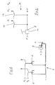
- Fig. 1
- ein schematisches Schaltbild der oberen Abschaltstufen eines Retarders in einer Ausführungsvariante einer Bremsanlage, und
- Fig. 2 und 3
- die Bremsanlage in einer zweiten Ausführungsvariante.
- Fig. 1
- a schematic circuit diagram of the upper shutdown stages of a retarder in a variant of a brake system, and
- 2 and 3
- the brake system in a second variant.
Eine Bremsanlage 1 für die blattgefederte Hinterachse 10 eines Nutzfahrzeugs sieht grundsätzlich ein fahrzeugfestes automatisch lastabhängiges Bremsregelventil, einen sog. ALB-Regler 3 vor, dessen Reglerhebel 4 über ein (nicht veranschaulichtes) Gestänge z.B. mit der Geberstange zwischen der ersten und der zweiten Hinterachse 10 eines Doppelachsaggregats verbunden ist. Entsprechend der Beladung des Fahrzeugs wird der Reglerhebel 3 mehr oder weniger in seiner Schwenkstellung ausgelenkt.A
Gemäß Ausführungsvariante nach Fig. 1 ist der Druckausgang 7 des ALB-Reglers 3 über eine Bremsleitung 12 mit den Bremszylindern der Hinterachse 10 verbunden. Bei teil- oder unbeladenem Fahrzeug wird somit an der Hinterachse 10 ein reduzierter Bremsdruck eingesteuert.1, the
Die Bremsleitung 12 bzw. der Druckausgang 7 des ALB-Reglers 3 ist ferner über eine Druckschalter-Steuerung 8 mit den einzelnen Bremsstufen R₁, R₂, ... R₆ verbunden, wobei jeder Bremsstufe jeweils ein Druckschalter 13 mit unterschiedlicher Druckschalt-Charakteristik zugeordnet ist. Der Retarder wird also bei zunehmendem Bremsdruck zunehmend in Betrieb gesetzt.The
Um auch bei leerem Fahrzeug unerwünschte Bremsverzögerungsrucke zu vermeiden bzw. kaum spürbar werden zu lassen, kann die Retarderwirkung bei leerem Fahrzeug (erforderlichenfalls auch bei Teilbeladung) derart reduziert werden, daß nicht mehr alle Stufen zum Einsatz kommen, sondern beispielsweise gemäß Ausführungsvariante der Fig. 1 die letzten beiden Retarderbremsstufen R₅, R₆ abgeschaltet werden. Die Abschaltung erfolgt durch eine elektrische Steuereinrichtung 2 mit einem Induktivsensor 5 , welcher in Abhängigkeit der Auslenkstellung des Reglerhebels 4 des ALB-Reglers 3 betätigbar ist. Elektrische Abschaltsignale betätigen insbesondere das Abschaltrelais 6 der fünften und/oder der sechsten Bremsstufe R₅, R₆ des Retarders. Die Abschaltung erfolgt beispielsweise bei einer Hinterachsbelastung von 25 bis 50% der maximalen Belastung, wenn sechs Bremsstufen des Retarders vorgesehen sind. Bei Retardern, die lediglich vier Schaltstufen besitzen, beispielsweise bei elektrischen Retardern oder Wirbelstrombremsen, können analog hierzu entweder die letzte, d.h. die vierte Stufe oder die letzten beiden, d.h. die dritte und die vierte Stufe abgeschaltet werden.In order to avoid unwanted braking deceleration jolts even when the vehicle is empty, or to make it barely noticeable, the retarder effect can be reduced when the vehicle is empty (if necessary also with partial load) so that not all stages are used, but rather, for example, according to the variant of FIG. 1 the last two retarder brake stages R₅, R₆ are switched off. It is switched off by an
Der Induktivsensor 5 kann auch ein anders gearteter Sensor sein. Er muß nicht unbedingt im Bereich des Reglerhebels 4 liegen, sondern kann auch auf ein benachbartes Gestänge einwirken, welches dem Reglerhebel 4 vorgekoppelt ist. Auch die Anordnung eines Sensors an der Geberstange zwischen erster und zweiter Hinterachse eines Doppelachsaggregates ist denkbar.The inductive sensor 5 can also be a different type of sensor. It does not necessarily have to lie in the area of the
Die Ausführungsvariante nach den Fig. 2 und 3 sieht eine elektrische Steuereinrichtung 2 zur Abschaltung der oberen Bremsstufen R₅, R₆ wie nach dem Ausführungsbeispiel der Fig. 1 vor. Demgegenüber ist die Druckschalter-Steuerung 8 zur Inbetriebnahme der einzelnen Bremsstufen R₁, R₂ ... des Retarders direkt an den Ausgang eines Motorwagenbremsventils 11 angeschlossen. Durch ein Potentiometer im Motorwagenbremsventil kann der Retarder der Betriebsbremse stufenlos vor- bzw. zugeschaltet werden. Die Begrenzung des Wirkungsmaximums ist durch entsprechenden Eingriff in die Steuerelektronik möglich.The embodiment variant according to FIGS. 2 and 3 provides an
Claims (7)
- A braking system (1) for commercial vehicles, with a service brake and a continuous service brake in the form of a multistage electric or hydraulic retarder, the upper braking stages (R5,R₆) of which can be cut out via an electric control means (2), characterized in that an automatic, load-dependent brake-regulating valve (3) is provided with a regulator lever (4) which is connected in a manner fixed to the vehicle with a leaf-sprung rear axle (10) of the commercial vehicle in such a way that the deflection position of the regulator lever (4) depends on the load condition of the commercial vehicle, and in that the electric control means (2) has an inductive sensor (5) for detecting the deflection values of the regulator lever (4) and for emitting electrical cut-out signals.
- A braking system according to Claim 1, characterised in that the upper braking stages (R5,R₆) can be progressively cut out upon exceeding respectively higher deflection values of the regulator lever (4).
- A braking system according to Claim 1 or 2, characterised in that the retarder is designed to be finely graduated, i.e. has at least six braking stages.
- A braking system according to any one of Claims 1 to 3, characterised in that the electric control means (2) has a respective cut-out relay (6) for the braking stage (R5,R₆) of the retarder to be cut out.
- A braking system according to any one of Claims 1 to 4, characterised in that the pressure output (7) of the ALB regulator (3) to the brake cylinders of the rear axle (10) is connected to a pressure switch control system (8) for cutting in the braking stages (R1,R2,...) of the multistage retarder (Figure 1).
- A braking system according to any one of Claims 1 to 5, characterised in that the retarder is connected upstream of the service brake, in particular the pressure switch control system (8) for cutting in the braking stages (R1,R2,...) of the multistage retarder is connected to the pressure output (9) of the motor vehicle brake valve (11) (Figure 3).
- A braking system according to Claim 6, characterised in that a potentiometer is provided in the motor vehicle brake valve (11) for the stepless series connection and switching on of the retarder to the service brake.
Applications Claiming Priority (4)
| Application Number | Priority Date | Filing Date | Title |
|---|---|---|---|
| DE4133430 | 1991-10-09 | ||
| DE4133430 | 1991-10-09 | ||
| DE4229222 | 1992-09-02 | ||
| DE4229222A DE4229222A1 (en) | 1991-10-09 | 1992-09-02 | BRAKE SYSTEM FOR COMMERCIAL VEHICLES WITH OPERATING AND CONTINUOUS BRAKES |
Publications (2)
| Publication Number | Publication Date |
|---|---|
| EP0536639A1 EP0536639A1 (en) | 1993-04-14 |
| EP0536639B1 true EP0536639B1 (en) | 1995-12-20 |
Family
ID=25908073
Family Applications (1)
| Application Number | Title | Priority Date | Filing Date |
|---|---|---|---|
| EP92116813A Expired - Lifetime EP0536639B1 (en) | 1991-10-09 | 1992-10-01 | Braking system for lorries with service brake and retarder |
Country Status (3)
| Country | Link |
|---|---|
| EP (1) | EP0536639B1 (en) |
| DE (2) | DE4229222A1 (en) |
| ES (1) | ES2082315T3 (en) |
Families Citing this family (1)
| Publication number | Priority date | Publication date | Assignee | Title |
|---|---|---|---|---|
| DE10144302A1 (en) * | 2001-09-10 | 2003-06-12 | Knorr Bremse Systeme | Braking device for vehicles which have a service brake system and a continuous brake system |
Family Cites Families (5)
| Publication number | Priority date | Publication date | Assignee | Title |
|---|---|---|---|---|
| FR2108951B1 (en) * | 1970-10-22 | 1973-11-23 | Labavia | |
| FR2312389A1 (en) * | 1975-05-27 | 1976-12-24 | Labavia | Eddy current brake switch device - has sector shaped cam on which rides ball running in guide and operating rod |
| DE2815294C2 (en) * | 1978-04-08 | 1980-06-19 | Zahnradfabrik Friedrichshafen Ag, 7990 Friedrichshafen | Control system of a hydrodynamic flow brake for vehicles |
| DE3101912A1 (en) * | 1981-01-22 | 1982-09-16 | Robert Bosch Gmbh, 7000 Stuttgart | Control device |
| US4962969A (en) * | 1988-09-30 | 1990-10-16 | Ford Motor Company | Adaptive controller for regenerative and friction braking system |
-
1992
- 1992-09-02 DE DE4229222A patent/DE4229222A1/en not_active Withdrawn
- 1992-10-01 DE DE59204749T patent/DE59204749D1/en not_active Expired - Fee Related
- 1992-10-01 ES ES92116813T patent/ES2082315T3/en not_active Expired - Lifetime
- 1992-10-01 EP EP92116813A patent/EP0536639B1/en not_active Expired - Lifetime
Also Published As
| Publication number | Publication date |
|---|---|
| DE4229222A1 (en) | 1993-04-15 |
| EP0536639A1 (en) | 1993-04-14 |
| DE59204749D1 (en) | 1996-02-01 |
| ES2082315T3 (en) | 1996-03-16 |
Similar Documents
| Publication | Publication Date | Title |
|---|---|---|
| EP0824433B1 (en) | Setpoint generator | |
| EP1528997B1 (en) | Integral brake system for motorcycles | |
| EP0520147A1 (en) | Control system for lifting or lowering the body of vehicles with pneumatic suspension | |
| EP3790748B1 (en) | Pneumatic spring control system, pneumatic spring system, vehicle comprising same, and method for same | |
| EP0447750A1 (en) | Brake system with at least one brake circuit | |
| EP0906859A1 (en) | Braking system for vehicles | |
| DE102018112846A1 (en) | Control device and method for controlling an actuator for actuating brake means of a vehicle, in particular a rail vehicle | |
| DE19604391A1 (en) | Braking system for vehicle | |
| EP0949130B2 (en) | Control device for a vehicle brake system | |
| DE19920096B4 (en) | Device for brake light control | |
| DE4214182C2 (en) | Brake pressure control device for brake pad wear optimization in a motor vehicle | |
| EP2534021B1 (en) | Method for operating a brake-slip regulating means of a brake system of a vehicle | |
| EP3900991A1 (en) | Method for controlling a pneumatic brake system of a trailer vehicle | |
| EP0546295A1 (en) | Semi-active undercarriage control system | |
| EP0956983B1 (en) | Device for controlling functions of a vehicle | |
| DE19527419C2 (en) | Method and device for controlling the brake system of a vehicle | |
| EP3847062B1 (en) | Distributed regulator structure for achieving optimised regulator properties and increased valve service life | |
| EP0927119A1 (en) | Method and device for determining a variable describing the speed of a vehicle | |
| DE3628681A1 (en) | Air suspension for vehicle with tandem axle | |
| EP1104731B1 (en) | Vehicle braking procedure | |
| EP0536639A1 (en) | Braking system for lorries with service brake and retarder | |
| DE19625341C2 (en) | Brake system for vehicles | |
| DE102013008655B4 (en) | Method for level control of a motor vehicle with air suspension | |
| DE3127476C2 (en) | ||
| EP0601480A1 (en) | Automatic load dependent brake force controller for commercial vehicle |
Legal Events
| Date | Code | Title | Description |
|---|---|---|---|
| PUAI | Public reference made under article 153(3) epc to a published international application that has entered the european phase |
Free format text: ORIGINAL CODE: 0009012 |
|
| AK | Designated contracting states |
Kind code of ref document: A1 Designated state(s): DE ES FR GB IT NL |
|
| 17P | Request for examination filed |
Effective date: 19930910 |
|
| 17Q | First examination report despatched |
Effective date: 19940513 |
|
| GRAA | (expected) grant |
Free format text: ORIGINAL CODE: 0009210 |
|
| AK | Designated contracting states |
Kind code of ref document: B1 Designated state(s): DE ES FR GB IT NL |
|
| ITF | It: translation for a ep patent filed | ||
| REF | Corresponds to: |
Ref document number: 59204749 Country of ref document: DE Date of ref document: 19960201 |
|
| ET | Fr: translation filed | ||
| REG | Reference to a national code |
Ref country code: ES Ref legal event code: FG2A Ref document number: 2082315 Country of ref document: ES Kind code of ref document: T3 |
|
| GBT | Gb: translation of ep patent filed (gb section 77(6)(a)/1977) |
Effective date: 19960326 |
|
| PLBE | No opposition filed within time limit |
Free format text: ORIGINAL CODE: 0009261 |
|
| 26N | No opposition filed | ||
| PGFP | Annual fee paid to national office [announced via postgrant information from national office to epo] |
Ref country code: GB Payment date: 19990924 Year of fee payment: 8 |
|
| PGFP | Annual fee paid to national office [announced via postgrant information from national office to epo] |
Ref country code: ES Payment date: 19991018 Year of fee payment: 8 |
|
| PGFP | Annual fee paid to national office [announced via postgrant information from national office to epo] |
Ref country code: NL Payment date: 19991029 Year of fee payment: 8 Ref country code: FR Payment date: 19991029 Year of fee payment: 8 Ref country code: DE Payment date: 19991029 Year of fee payment: 8 |
|
| PG25 | Lapsed in a contracting state [announced via postgrant information from national office to epo] |
Ref country code: GB Free format text: LAPSE BECAUSE OF NON-PAYMENT OF DUE FEES Effective date: 20001001 |
|
| PG25 | Lapsed in a contracting state [announced via postgrant information from national office to epo] |
Ref country code: ES Free format text: LAPSE BECAUSE OF NON-PAYMENT OF DUE FEES Effective date: 20001002 |
|
| PG25 | Lapsed in a contracting state [announced via postgrant information from national office to epo] |
Ref country code: NL Free format text: LAPSE BECAUSE OF NON-PAYMENT OF DUE FEES Effective date: 20010501 |
|
| GBPC | Gb: european patent ceased through non-payment of renewal fee |
Effective date: 20001001 |
|
| PG25 | Lapsed in a contracting state [announced via postgrant information from national office to epo] |
Ref country code: FR Free format text: LAPSE BECAUSE OF NON-PAYMENT OF DUE FEES Effective date: 20010629 |
|
| NLV4 | Nl: lapsed or anulled due to non-payment of the annual fee |
Effective date: 20010501 |
|
| PG25 | Lapsed in a contracting state [announced via postgrant information from national office to epo] |
Ref country code: DE Free format text: LAPSE BECAUSE OF NON-PAYMENT OF DUE FEES Effective date: 20010703 |
|
| REG | Reference to a national code |
Ref country code: FR Ref legal event code: ST |
|
| REG | Reference to a national code |
Ref country code: ES Ref legal event code: FD2A Effective date: 20011113 |
|
| PG25 | Lapsed in a contracting state [announced via postgrant information from national office to epo] |
Ref country code: IT Free format text: LAPSE BECAUSE OF NON-PAYMENT OF DUE FEES;WARNING: LAPSES OF ITALIAN PATENTS WITH EFFECTIVE DATE BEFORE 2007 MAY HAVE OCCURRED AT ANY TIME BEFORE 2007. THE CORRECT EFFECTIVE DATE MAY BE DIFFERENT FROM THE ONE RECORDED. Effective date: 20051001 |