EP0535571A2 - Modified Huffman encode/decode system with simplified decoding for imaging systems - Google Patents
Modified Huffman encode/decode system with simplified decoding for imaging systems Download PDFInfo
- Publication number
- EP0535571A2 EP0535571A2 EP92116555A EP92116555A EP0535571A2 EP 0535571 A2 EP0535571 A2 EP 0535571A2 EP 92116555 A EP92116555 A EP 92116555A EP 92116555 A EP92116555 A EP 92116555A EP 0535571 A2 EP0535571 A2 EP 0535571A2
- Authority
- EP
- European Patent Office
- Prior art keywords
- symbols
- codeword
- bits
- symbol
- image
- Prior art date
- Legal status (The legal status is an assumption and is not a legal conclusion. Google has not performed a legal analysis and makes no representation as to the accuracy of the status listed.)
- Withdrawn
Links
Images


Classifications
-
- H—ELECTRICITY
- H04—ELECTRIC COMMUNICATION TECHNIQUE
- H04N—PICTORIAL COMMUNICATION, e.g. TELEVISION
- H04N19/00—Methods or arrangements for coding, decoding, compressing or decompressing digital video signals
- H04N19/30—Methods or arrangements for coding, decoding, compressing or decompressing digital video signals using hierarchical techniques, e.g. scalability
- H04N19/39—Methods or arrangements for coding, decoding, compressing or decompressing digital video signals using hierarchical techniques, e.g. scalability involving multiple description coding [MDC], i.e. with separate layers being structured as independently decodable descriptions of input picture data
Definitions
- the present invention is related to a flexible encoding/decoding method for digital images using Huffman codes. More particularly, the invention relates to a method of encoding digital images with one maximum codeword length and decoding the encoded digital image with the same or a lesser maximum codeword length which may be selected as desired without regard to the maximum codeword length with which the encoding was performed.
- a digital image may be compressed without loss of information or image quality by encoding each of the symbols or pixel values representing the image in such a way as to reduce the total number of bits representing the digital image.
- the compression permits more images to be recorded on a given disk and speeds up the playback process.
- the symbols to be encoded are classified in accordance with their frequency of occurrence in the type of digital image being encoded. From this, a code table is constructed as follows: Each symbol is associated with a unique codeword whose length is an inverse function of the frequency of occurrence of the symbol in the digital image. Thus, the most frequently occurring symbol is encoded to the shortest codeword, a lesser frequently occurring symbol is encoded to a longer codeword and the least frequently occurring symbol is encoded to the longest codeword.
- This method is particularly powerful if, prior to the above-described encoding process, the original image is first subjected to a conventional differencing process (such as delta modulation or differential pulse code modulation) which emphasizes differences among the image pixels. Since most images contain many repetitive pixels (e.g., a blue sky), the most frequently occurring symbol in the processed image is zero. In this exemplary encoding scheme, the symbol zero would be encoded to the shortest codeword.
- a code table of this type is Table A of Fig. 1. In Table A, the symbols are listed in their order of frequency of occurrence, not necessarily in order of their magnitudes.
- the symbol labelled "0” is the most frequently occurring symbol (which in this case happens to be the symbol of Zero value), the symbol labelled "1" is the next frequently occurring, and so forth.
- the maximum codeword length is 8 bits (i.e., the length of the last symbol in Table A). The more symbols to be decoded, the greater the maximum codeword length.
- a conventional decoder converts the codewords back into the appropriate symbols in accordance with the code table during playback.
- One problem that arises is that the speed at which the decoder operates and the complexity of the decoder is determined at least in part by the maximum codeword length. Limiting the maximum codeword length (e.g., to 8 bits as in Table A) limits the number of allowable symbols, requiring that the digital image pixels be quantized to a limited number of amplitude levels (one for each allowable symbol) which introduces quantization error into the digital image. To reduce such quantization error, the number of allowable symbols must be increased, by increasing the maximum codeword length in the code table, thereby increasing the complexity of the decoder and reducing its speed. The number of allowable symbols can also be increased by lengthening some of the symbols, which reduces the compression.
- U.S. Patent No. 3,883,847 to Frank discloses a method of decoding employing two code tables such as (for example) Tables A and B of Fig. 1. While Table A (maximum codeword length 8-bits) defines the codewords for the seven most frequently occurring symbols, Table B (codeword length 11-bits) defines the codewords for the three least frequent symbols. This permits the image to be quantized to ten quantization levels. Most of the time, the decoder operates as a decoder of maximum codeword length 8-bits. For a small fraction of the total time, the decoder must refer to Table B and operate as a decoder of maximum codeword length 11-bits, thereby incurring a relatively small penalty for the capability of handling three additional symbols.
- Table A maximum codeword length 8-bits
- Table B codeword length 11-bits
- variable-length code Another decoding strategy involves the principle of converting the variable-length code to a fixed length code prior to symbol decoding.
- each variable length codeword is converted to a fixed length integer, and then the integer is used to index a table of fixed-length characters. This technique has the advantage of a reduced memory requirement.
- the structure of the decoder is dictated by the structure of the encoder.
- the decoder must employ both Table A and Table B.
- One variation in the decoder structure may be to dispense with Table B and assign an arbitrary value to all escape codewords, ignoring the last three bits thereof.
- the decoder operates as a decoder of maximum codeword length either 11 bits or (in the variation suggested herein) 8 bits. No other variations are possible without modifying the code table.
- FIG. 2 The recording of an image in accordance with this hierarchy is illustrated in Fig. 2.
- An original image (100) having 2048 horizontal line resolution is decimated (sub-sampled) twice (102, 104) to produce versions of the same image having 1024 and 512 horizontal line resolution respectively (106, 108), the latter being recorded as the base image.
- the base image is interpolated (110) to a 1024 horizontal line image (112) which is subtracted (114) from the decimated 1024 line image in a differencing process of the type mentioned previously herein.
- the difference is then quantized and Huffman encoded (116) to produce a 1024 horizontal line residual ("4 Base") image which is recorded on the CD.
- a similar process illustrated in Fig. 2 (at 110', 112', 114' and 116') is employed to construct a 2048 line ("16 Base") residual image which is also recorded on the CD.
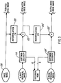
- the playback of an image in this hierarchy is illustrated in Fig. 3.
- the base image 108 may simply be played back without any enhancement.
- a higher resolution (1024 horizontal line) image is obtained, however, by Huffman decoding (118) the 4 Base image, interpolating (120) the base image and adding (122) them together.
- a similar process illustrated in Fig. 3 (at 118', 120' and 122') produces the highest quality (2048 horizontal line resolution) image using the Base image, the 4 Base residual image and the 16 Base residual image.
- the foregoing hierarchy permits CD players of different complexities to play back the recorded image at different levels of image quality, satisfying different market demands.
- the problem is that the decoder structure in all of the different CD players must be the same because the Huffman decoding processes 118 and 118' of Fig. 3 must be the precise reverse of the Huffman encoding processes 116 and 116' of Fig. 2.
- the Huffman encode/decode example of Fig. 1 the only possible variation is that the more economical CD players may forego Table B and simply assign an arbitrary value to the ESCAPE codeword. This single variation fails to reflect the diverse variations of playback image quality permitted by the CD image recording/playback hierarchy of Fig.'s 2 and 3.
- the prior art allows no flexibility in the decoder structure and cost. It should be noted that the cost of the decoder is a fraction of the cost of the memory or ROM.
- the invention is a method of encoding and decoding a digital image in which the encoding is carried out with a code table characterized by a certain maximum codeword length, the method permitting the decoding of the encoded image to be carried out by any one of many different decoders characterized by different maximum codeword lengths.
- the digitized image is first subjected to a differencing process which produces a difference image of positive and negative symbols (pixel values) in an alphabet of 2N+1 symbols of which the most frequently occurring symbol is the zero symbol.
- the zero symbol is mapped to the shortest codeword.
- the K most frequently occurring positive symbols are mapped to a set of K codewords, and the K most frequently occurring negative symbols are mapped to another set of K codewords.
- the length of each codeword is an inverse function of the frequency of occurrence of the corresponding symbol in the image and the longest codeword is of length d bits.
- the remaining N-K positive symbols and N-K negative symbols are mapped in order of their magnitudes to respective sets of supplementary codewords of a uniform maximum length D bits.
- each supplementary codeword form a prefix which is uniform within each set and specifies whether the corresponding symbol is positive or negative.
- the remaining or least significant D-d bits of each supplementary codeword comprise a suffix and are mapped in order of bit position to progressively more narrow ranges of symbol values of the remaining N-K positive symbols and the N-K negative symbols. Each bit thereof is mapped to a value obtained by interpolating between the maximum and minimum symbol values spanning the corresponding range.
- the least significant bit (the D th bit) of the suffix specifies the exact symbol value.
- the prefix specifies the sign while the suffix specifies an absolute value.
- One advantage of the invention is that the decoder can ignore any number or all of the bits of the suffix of each supplementary codeword.
- the number or variety of decoder designs is equal to the number (D-d) of bits in the suffix of the supplementary codewords. Accordingly, the invention provides far more flexibility in selecting bit resolution and complexity in the decoder.
- a decoder of the simplest or most economical design would ignore all D-d bits of the suffix of any supplementary codeword. Such a decoder would map the prefix of the positively-prefixed supplementary codewords to a value computed by selecting a value between the maximum and minimum of the N-K least frequently occurring positive symbols. Similarly, it would map the prefix of the negatively-prefixed supplementary codewords to a value computed by selecting a value between the maximum and minimum of the N-K least frequently occurring negative symbols.
- Another advantage of the invention is that it automatically provides for discriminating between positive and negative symbols using a single code table.
- Fig. 1 illustrates a pair of modified Huffman encoding tables in accordance with prior art techniques.
- Fig. 2 illustrates a process for processing digital images prior to recording on a CD in accordance with the U.S. Patent referred to above.
- Fig. 3 illustrates the corresponding process for playing back and processing the images recorded in the process of Fig. 2.
- Fig. 4 is a diagram illustrating the structure of an exemplary code table of the present invention.
- Fig. 5 is a block diagram illustrating an encoder embodying one aspect of the invention.
- Fig. 6 illustrates the encoding process carried out by the encoder of Fig. 5.
- Fig. 7 is a block diagram illustrating a decoder embodying another aspect of the invention.
- Fig. 8 illustrates the decoding process carried out by the decoder of Fig. 7.
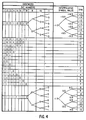
- Fig. 4 illustrates one example of a code table embodying one aspect of the invention.
- the digital image to be encoded has been quantized and subjected to a differencing process to produce a difference image.
- the difference image consists of pixel values or symbols in a symbol alphabet having sixteen positive symbols (0 through 15) and fifteen negative symbols (-1 through -15). Thus, each pixel would be represented by a symbol comprising four bits and a sign bit. Because images typically contain may repetitive pixels (e.g., blue sky), the most frequently occurring symbol is 0. The eight most frequently occurring positive symbols are labelled (in the "SYMBOL" column of Fig.
- the remaining (least frequently occurring) eight positive symbols are arranged in the SYMBOL column of Fig. 4 in order of increasing value 8 through 15.
- the codewords for each of these symbols are of the same uniform length (eleven bits) and all begin with the same 8-bit prefix (i.e., 11111111).
- This prefix specifies a positive symbol in the range of values 8 through 15.
- this prefix is mapped to a symbol value obtained by interpolating between the maximum and minimum values (15 and 8) of the corresponding range, namely 11.5, as indicated in the diagram of Fig. 4.
- Such a decoder performs as if the code had a maximum codeword length of eight bits.
- the 8-bit prefix 10010010 of the codewords for the eight remaining (least frequently occurring) negative symbols is mapped to the interpolated symbol value -11.5.
- the suffix consists of 3 bits, namely the ninth, tenth and eleventh most significant bits of the codeword.
- the ninth most significant bit specifies which half of the total range of values 8 through 15 the symbol belongs.
- Fig. 4 shows that if the ninth most significant bit is 1, then the codeword is mapped to a value obtained by selecting a value between the maximum and minimum symbol values in the highest half of the range (i.e., 15 and 11), or 13.5. If the ninth bit is zero, the mapped value is obtained by selecting a value between 11 and 8, or 9.5. For negative symbols, the selected values are -13.5 and -9.5, respectively.
- the decoder thus maps the appropriate nine bit codeword pattern to the corresponding selected symbol value. Such a decoder performs as if the maximum codeword length of the code were nine bits.
- the tenth most significant bit indicates within the half of the range specified by the ninth most significant bit which quarter of the range the symbol belongs. For a decoder of the invention which reads no more than the ten most significant bits of any codeword, if the ninth most significant bit is 1 (specifying the upper half of the range between 8 and 15), then a tenth most significant bit of 1 or 0 specifies that the symbol lies in the range including 14 through 15 or 12 through 13, respectively, corresponding to selected values of 14.5 or 12.5, respectively. For negative symbols, the selected values are -14.5 or -12.5, respectively.
- a tenth most significant bit of 1 or 0 specifies that the symbol lies in the range including 10 through 11 or 8 through 9, respectively, corresponding to selected values of 10.5 or 8.5, respectively.
- the selected values are -10.5 or -8.5, respectively.
- the decoder maps the appropriate ten bit codeword pattern to the corresponding selected symbol value. Such a decoder performs as if the maximum codeword length of the code were ten bits.
- the last bit of the suffix maps directly to the exact symbol value, as indicated in the drawing.
- a decoder of the invention which reads as many as eleven most significant bits of any codeword provides the maximum resolution and quality.
- the number of bits in the suffix may be increased, thereby increasing the number of symbols which may be encoded and increasing the number of possible decoder designs accordingly.
- Fig. 5 illustrates an implementation of the encoder of the invention.
- the bits representing the incoming symbols are serially shifted symbol by symbol into a shift register 200.
- An encoder read only memory (ROM) 204 stores a look-up table mapping each symbol to a corresponding codeword (in accordance with the diagram of Fig. 4, for example).
- the ROM 204 responds to the symbol received from the parallel outputs of the register 200 by outputting a codeword to the parallel inputs of an output shift register 206.
- the ROM 204 also outputs the number of bits in the codeword to a shift controller 208.
- the shift controller 208 causes the output shift register 206 to shift a number of bits out of its serial output equal to the number of bits in the codeword.
- the data shifted out are transmitted to a recording device.
- the next step (block 212) is to apply these bits to the address input of the ROM 204.
- the ROM 204 outputs the corresponding codeword (block 214) to the output shift register 206 and outputs the number of bits in the codeword (block 216) to the shift controller 208.
- the shift controller 208 then causes the shift register to shift out the bits in the codeword (block 218 of Figure 6).
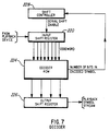
- Fig. 7 illustrates one embodiment of a decoder of the invention.
- Data from a playback device are serially clocked into an input shift register 220.
- the length of the input shift register 220 determines the number of bits in a codeword which the decoder can read.
- the contents of the input shift register 220 are applied in parallel to the address input of a decoder ROM 224.
- the decoder ROM 224 stores a look-up table embodying at least a part of the code illustrated in the diagram of Fig. 4. It maps the codeword stored in the input shift register 220 to the corresponding symbol and outputs the symbol to the parallel input of an output shift register 226.
- the ROM 224 also outputs the number of bits in the codeword to a shift controller 228.
- the shift controller 228 shifts a number of bits into the serial input of the input shift register 220 equal to the number of bits in the previous codeword.
- the decoding process performed by the decoder of Fig. 7 is illustrated in Fig. 8.
- the decoder is initialized in block 230 of Fig. 8 by filling the input shift register 220 with the first M bits of the encoded data (where the shift register is M bits long).
- the contents Of the input register 220 is applied through its parallel output to the address input of the decoder ROM 224 (block 232 of Fig. 8).
- the codeword may comprise as few as the two first received or most significant bits of the M bits in the input shift register 220.
- the decoder ROM 224 responds to the codeword bits by outputting the corresponding symbol to the output shift register 226, ignoring the remaining (last received or least significant) bits in the input register 220 (block 234 of Fig. 8).
- the decoder ROM 224 also outputs the number of bits in the codeword to the shift controller 228 (block 236 of Fig. 8).
- the shift controller causes this number of bits of encoded data to be shifted into the serial input of the input shift register 220 (block 238 of Fig. 8). The process then repeats beginning with the step of block 232.
- the decoder design may be varied by changing the length (number of bits) of the input shift register 220. It should be at least as long as the two codeword prefixes of the supplementary codewords and need be no longer than the supplementary codeword length. In the example of Fig. 4, the shift register may be as short as eight bits and need be no longer than eleven bits.
- the length of the input shift register 220 determines the maximum codeword length which the decoder will read.
- the decoder input shift register in this example can have length 8, 9, 10 or 11 bits.
- the decoder table changes. For example, in a decoder which reads a maximum codeword length of 8 bits, the decoder ROM 224 stores a look-up table corresponding to the eight most significant bits (bits 1 through 8) of the diagram of Fig. 4. If it is to read maximum codeword length of 9 bits, the look-up table corresponds to the nine most significant bits (bits 1 through 9) of the diagram of Fig. 4, and so forth. In the latter embodiment, the look-up table maps the ninth bit to the appropriate interpolated symbol value, in accordance with the diagram of Fig. 4.
- the encoder of Fig. 5 is employed in carrying out the encoding steps 116 and 116'.
- the 4 Base residual image contains proportionately more important information than the 16 Base residual image. Therefore, the decoding step 118 of the 4 Base residual image is more critical than the decoding step 118' for the 16 Base residual image. Accordingly, it may be desireable to employ decoders of the type illustrated in Fig. 5 with the input register 220 of a maximum length for carrying out the decoding step 118 for the 4 Base residual image and with the input register 220 of a shorter length for carrying out the decoding step 118' for the 16 Base residual image.
Abstract
The K most frequently occurring symbols in an image represented by an alphabet of N symbols are mapped to a set of K codewords. The length of each codeword is an inverse function of the frequency of occurrence of the corresponding symbol in the image and the longest codeword is of length d bits. The remaining N-K symbols are mapped in order of their magnitude to a set of supplementary codewords of a uniform maximum length D bits. The d most significant bits of each supplementary codeword form a prefix which is uniform within each set and specifies whether the corresponding symbol is positive or negative. The remaining or least significant D-d bits of each supplementary codeword comprise a suffix and are mapped in order of bit position to progressively more narrow ranges of symbol values of the remaining N-K symbols.
Description
- The present invention is related to a flexible encoding/decoding method for digital images using Huffman codes. More particularly, the invention relates to a method of encoding digital images with one maximum codeword length and decoding the encoded digital image with the same or a lesser maximum codeword length which may be selected as desired without regard to the maximum codeword length with which the encoding was performed.
- A digital image may be compressed without loss of information or image quality by encoding each of the symbols or pixel values representing the image in such a way as to reduce the total number of bits representing the digital image. If the digital image is to be recorded on media such as an optical disk, the compression permits more images to be recorded on a given disk and speeds up the playback process. To accomplish this, the symbols to be encoded are classified in accordance with their frequency of occurrence in the type of digital image being encoded. From this, a code table is constructed as follows: Each symbol is associated with a unique codeword whose length is an inverse function of the frequency of occurrence of the symbol in the digital image. Thus, the most frequently occurring symbol is encoded to the shortest codeword, a lesser frequently occurring symbol is encoded to a longer codeword and the least frequently occurring symbol is encoded to the longest codeword.
- This method is particularly powerful if, prior to the above-described encoding process, the original image is first subjected to a conventional differencing process (such as delta modulation or differential pulse code modulation) which emphasizes differences among the image pixels. Since most images contain many repetitive pixels (e.g., a blue sky), the most frequently occurring symbol in the processed image is zero. In this exemplary encoding scheme, the symbol zero would be encoded to the shortest codeword. One example of a code table of this type is Table A of Fig. 1. In Table A, the symbols are listed in their order of frequency of occurrence, not necessarily in order of their magnitudes. Thus, the symbol labelled "0", is the most frequently occurring symbol (which in this case happens to be the symbol of Zero value), the symbol labelled "1" is the next frequently occurring, and so forth. The maximum codeword length is 8 bits (i.e., the length of the last symbol in Table A). The more symbols to be decoded, the greater the maximum codeword length.
- When the digital image is played back, a conventional decoder converts the codewords back into the appropriate symbols in accordance with the code table during playback. One problem that arises is that the speed at which the decoder operates and the complexity of the decoder is determined at least in part by the maximum codeword length. Limiting the maximum codeword length (e.g., to 8 bits as in Table A) limits the number of allowable symbols, requiring that the digital image pixels be quantized to a limited number of amplitude levels (one for each allowable symbol) which introduces quantization error into the digital image. To reduce such quantization error, the number of allowable symbols must be increased, by increasing the maximum codeword length in the code table, thereby increasing the complexity of the decoder and reducing its speed. The number of allowable symbols can also be increased by lengthening some of the symbols, which reduces the compression.
- U.S. Patent No. 3,883,847 to Frank discloses a method of decoding employing two code tables such as (for example) Tables A and B of Fig. 1. While Table A (maximum codeword length 8-bits) defines the codewords for the seven most frequently occurring symbols, Table B (codeword length 11-bits) defines the codewords for the three least frequent symbols. This permits the image to be quantized to ten quantization levels. Most of the time, the decoder operates as a decoder of maximum codeword length 8-bits. For a small fraction of the total time, the decoder must refer to Table B and operate as a decoder of maximum codeword length 11-bits, thereby incurring a relatively small penalty for the capability of handling three additional symbols. The last entry in Table A is the "ESCAPE" codeword having eight binary ones. Most of the time the decoder refers to Table A and in the rare instances that the decoder encounters the escape codeword, it knows that the codeword is 11 bits long and refers to Table B. A similar implementation of this type of technique is disclosed by Hankamer, "A Modified Huffman Procedure with Reduced Memory Requirement", IEEE Transactions on Communications, Vol. COM-27, No. 6, pp. 930-932 (June 1979).
- Another decoding strategy involves the principle of converting the variable-length code to a fixed length code prior to symbol decoding. In U.S. Patent No. 4,044,347 to VanVoorhis, each variable length codeword is converted to a fixed length integer, and then the integer is used to index a table of fixed-length characters. This technique has the advantage of a reduced memory requirement.
- Even with the foregoing technique, a significant problem remains that the structure of the decoder is dictated by the structure of the encoder. The decoder must employ both Table A and Table B. One variation in the decoder structure may be to dispense with Table B and assign an arbitrary value to all escape codewords, ignoring the last three bits thereof. Thus, the decoder operates as a decoder of maximum codeword length either 11 bits or (in the variation suggested herein) 8 bits. No other variations are possible without modifying the code table.
- This is a particularly significant disadvantage when the foregoing techniques are applied to recording photographic images on a compact disk (CD), as disclosed in U.S. Patent No. 4,969,204 assigned to the present assignee. In this application, a hierarchy of different quality versions of the same image may be played back by CD players of different complexities and designs.
- The recording of an image in accordance with this hierarchy is illustrated in Fig. 2. An original image (100) having 2048 horizontal line resolution is decimated (sub-sampled) twice (102, 104) to produce versions of the same image having 1024 and 512 horizontal line resolution respectively (106, 108), the latter being recorded as the base image. The base image is interpolated (110) to a 1024 horizontal line image (112) which is subtracted (114) from the decimated 1024 line image in a differencing process of the type mentioned previously herein. The difference is then quantized and Huffman encoded (116) to produce a 1024 horizontal line residual ("4 Base") image which is recorded on the CD. A similar process illustrated in Fig. 2 (at 110', 112', 114' and 116') is employed to construct a 2048 line ("16 Base") residual image which is also recorded on the CD.
- The playback of an image in this hierarchy is illustrated in Fig. 3. The
base image 108 may simply be played back without any enhancement. A higher resolution (1024 horizontal line) image is obtained, however, by Huffman decoding (118) the 4 Base image, interpolating (120) the base image and adding (122) them together. A similar process illustrated in Fig. 3 (at 118', 120' and 122') produces the highest quality (2048 horizontal line resolution) image using the Base image, the 4 Base residual image and the 16 Base residual image. - The foregoing hierarchy permits CD players of different complexities to play back the recorded image at different levels of image quality, satisfying different market demands. The problem, however, is that the decoder structure in all of the different CD players must be the same because the Huffman
decoding processes 118 and 118' of Fig. 3 must be the precise reverse of the Huffmanencoding processes 116 and 116' of Fig. 2. In the Huffman encode/decode example of Fig. 1, the only possible variation is that the more economical CD players may forego Table B and simply assign an arbitrary value to the ESCAPE codeword. This single variation fails to reflect the diverse variations of playback image quality permitted by the CD image recording/playback hierarchy of Fig.'s 2 and 3. It also fails to reflect the need to fit CD player manufacturing costs within different narrow niches of various specific markets in which they are to be sold. For all practical purposes, the prior art allows no flexibility in the decoder structure and cost. It should be noted that the cost of the decoder is a fraction of the cost of the memory or ROM. - Therefore, it is an object of the invention to permit a wide range of design complexity and performance levels in the decoder design of the image CD player. Specifically, it is an object of the invention to permit the same recorded image to be played back with many different decoders operating with different maximum codeword lengths within a predetermined range.
- The invention is a method of encoding and decoding a digital image in which the encoding is carried out with a code table characterized by a certain maximum codeword length, the method permitting the decoding of the encoded image to be carried out by any one of many different decoders characterized by different maximum codeword lengths.
- Preferably, the digitized image is first subjected to a differencing process which produces a difference image of positive and negative symbols (pixel values) in an alphabet of 2N+1 symbols of which the most frequently occurring symbol is the zero symbol. The zero symbol is mapped to the shortest codeword. The K most frequently occurring positive symbols are mapped to a set of K codewords, and the K most frequently occurring negative symbols are mapped to another set of K codewords. The length of each codeword is an inverse function of the frequency of occurrence of the corresponding symbol in the image and the longest codeword is of length d bits. The remaining N-K positive symbols and N-K negative symbols are mapped in order of their magnitudes to respective sets of supplementary codewords of a uniform maximum length D bits. The d most significant bits of each supplementary codeword form a prefix which is uniform within each set and specifies whether the corresponding symbol is positive or negative. The remaining or least significant D-d bits of each supplementary codeword comprise a suffix and are mapped in order of bit position to progressively more narrow ranges of symbol values of the remaining N-K positive symbols and the N-K negative symbols. Each bit thereof is mapped to a value obtained by interpolating between the maximum and minimum symbol values spanning the corresponding range. The least significant bit (the Dth bit) of the suffix specifies the exact symbol value. In the preferred embodiment, the prefix specifies the sign while the suffix specifies an absolute value.
- One advantage of the invention is that the decoder can ignore any number or all of the bits of the suffix of each supplementary codeword. Thus, the number or variety of decoder designs is equal to the number (D-d) of bits in the suffix of the supplementary codewords. Accordingly, the invention provides far more flexibility in selecting bit resolution and complexity in the decoder.
- As one example, a decoder of the simplest or most economical design would ignore all D-d bits of the suffix of any supplementary codeword. Such a decoder would map the prefix of the positively-prefixed supplementary codewords to a value computed by selecting a value between the maximum and minimum of the N-K least frequently occurring positive symbols. Similarly, it would map the prefix of the negatively-prefixed supplementary codewords to a value computed by selecting a value between the maximum and minimum of the N-K least frequently occurring negative symbols.
- Another advantage of the invention is that it automatically provides for discriminating between positive and negative symbols using a single code table.
- Fig. 1 illustrates a pair of modified Huffman encoding tables in accordance with prior art techniques.
- Fig. 2 illustrates a process for processing digital images prior to recording on a CD in accordance with the U.S. Patent referred to above.
- Fig. 3 illustrates the corresponding process for playing back and processing the images recorded in the process of Fig. 2.
- Fig. 4 is a diagram illustrating the structure of an exemplary code table of the present invention.
- Fig. 5 is a block diagram illustrating an encoder embodying one aspect of the invention.
- Fig. 6 illustrates the encoding process carried out by the encoder of Fig. 5.
- Fig. 7 is a block diagram illustrating a decoder embodying another aspect of the invention.
- Fig. 8 illustrates the decoding process carried out by the decoder of Fig. 7.
- Fig. 4 illustrates one example of a code table embodying one aspect of the invention. In this example, the digital image to be encoded has been quantized and subjected to a differencing process to produce a difference image. The difference image consists of pixel values or symbols in a symbol alphabet having sixteen positive symbols (0 through 15) and fifteen negative symbols (-1 through -15). Thus, each pixel would be represented by a symbol comprising four bits and a sign bit. Because images typically contain may repetitive pixels (e.g., blue sky), the most frequently occurring symbol is 0. The eight most frequently occurring positive symbols are labelled (in the "SYMBOL" column of Fig. 4) 0 through 7 in order of their frequency of occurrence in the image (not necessarily in order of value) and are mapped in the diagram of Fig. 4 to eight codewords of increasing codeword length (i.e., 00 through 11111110). Similarly, the seven most frequently occurring negative symbols are labelled -1 through -7 in order of their frequency of occurrence and are mapped in the diagram of Fig. 4 to seven codewords of increasing length (i.e., 011 through 10010011).
- The remaining (least frequently occurring) eight positive symbols are arranged in the SYMBOL column of Fig. 4 in order of increasing
value 8 through 15. The codewords for each of these symbols are of the same uniform length (eleven bits) and all begin with the same 8-bit prefix (i.e., 11111111). This prefix specifies a positive symbol in the range ofvalues 8 through 15. In a decoder of the invention which reads at most only the eight most significant bits of any codeword, this prefix is mapped to a symbol value obtained by interpolating between the maximum and minimum values (15 and 8) of the corresponding range, namely 11.5, as indicated in the diagram of Fig. 4. Such a decoder performs as if the code had a maximum codeword length of eight bits. - Similarly, the 8-bit prefix 10010010 of the codewords for the eight remaining (least frequently occurring) negative symbols is mapped to the interpolated symbol value -11.5.
- In the example of Fig. 4, the suffix consists of 3 bits, namely the ninth, tenth and eleventh most significant bits of the codeword. For a decoder of the invention which reads no more than the nine most significant bits of any codeword, the ninth most significant bit specifies which half of the total range of
values 8 through 15 the symbol belongs. Thus, Fig. 4 shows that if the ninth most significant bit is 1, then the codeword is mapped to a value obtained by selecting a value between the maximum and minimum symbol values in the highest half of the range (i.e., 15 and 11), or 13.5. If the ninth bit is zero, the mapped value is obtained by selecting a value between 11 and 8, or 9.5. For negative symbols, the selected values are -13.5 and -9.5, respectively. The decoder thus maps the appropriate nine bit codeword pattern to the corresponding selected symbol value. Such a decoder performs as if the maximum codeword length of the code were nine bits. - The tenth most significant bit indicates within the half of the range specified by the ninth most significant bit which quarter of the range the symbol belongs. For a decoder of the invention which reads no more than the ten most significant bits of any codeword, if the ninth most significant bit is 1 (specifying the upper half of the range between 8 and 15), then a tenth most significant bit of 1 or 0 specifies that the symbol lies in the range including 14 through 15 or 12 through 13, respectively, corresponding to selected values of 14.5 or 12.5, respectively. For negative symbols, the selected values are -14.5 or -12.5, respectively. Similarly, if the ninth most significant bit is 0, then a tenth most significant bit of 1 or 0 specifies that the symbol lies in the range including 10 through 11 or 8 through 9, respectively, corresponding to selected values of 10.5 or 8.5, respectively. For negative symbols, the selected values are -10.5 or -8.5, respectively. The decoder maps the appropriate ten bit codeword pattern to the corresponding selected symbol value. Such a decoder performs as if the maximum codeword length of the code were ten bits.
- In the example of Fig. 4, the last bit of the suffix (the eleventh most significant codeword bit) maps directly to the exact symbol value, as indicated in the drawing. Thus, a decoder of the invention which reads as many as eleven most significant bits of any codeword provides the maximum resolution and quality.
Of course, it should be apparent from the foregoing that the skilled worker can implement many variations of the theme exemplified by the embodiment of Fig. 4. For example, the number of bits in the suffix may be increased, thereby increasing the number of symbols which may be encoded and increasing the number of possible decoder designs accordingly. - Fig. 5 illustrates an implementation of the encoder of the invention. The bits representing the incoming symbols are serially shifted symbol by symbol into a
shift register 200. An encoder read only memory (ROM) 204 stores a look-up table mapping each symbol to a corresponding codeword (in accordance with the diagram of Fig. 4, for example). TheROM 204 responds to the symbol received from the parallel outputs of theregister 200 by outputting a codeword to the parallel inputs of anoutput shift register 206. TheROM 204 also outputs the number of bits in the codeword to ashift controller 208. Theshift controller 208 causes theoutput shift register 206 to shift a number of bits out of its serial output equal to the number of bits in the codeword. The data shifted out are transmitted to a recording device. - This encoding operation is illustrated in Fig. 6. The first step (block 210 of Fig. 6) is to shift in m bits of data into the
shift register 200, where m is the number of bits per symbol. In the example of Fig. 4, m=5. The next step (block 212) is to apply these bits to the address input of theROM 204. Then, theROM 204 outputs the corresponding codeword (block 214) to theoutput shift register 206 and outputs the number of bits in the codeword (block 216) to theshift controller 208. Theshift controller 208 then causes the shift register to shift out the bits in the codeword (block 218 of Figure 6). - Fig. 7 illustrates one embodiment of a decoder of the invention. Data from a playback device are serially clocked into an
input shift register 220. The length of theinput shift register 220 determines the number of bits in a codeword which the decoder can read. The contents of theinput shift register 220 are applied in parallel to the address input of adecoder ROM 224. Thedecoder ROM 224 stores a look-up table embodying at least a part of the code illustrated in the diagram of Fig. 4. It maps the codeword stored in theinput shift register 220 to the corresponding symbol and outputs the symbol to the parallel input of anoutput shift register 226. TheROM 224 also outputs the number of bits in the codeword to ashift controller 228. Theshift controller 228 shifts a number of bits into the serial input of theinput shift register 220 equal to the number of bits in the previous codeword. - The decoding process performed by the decoder of Fig. 7 is illustrated in Fig. 8. The decoder is initialized in
block 230 of Fig. 8 by filling theinput shift register 220 with the first M bits of the encoded data (where the shift register is M bits long). The contents Of theinput register 220 is applied through its parallel output to the address input of the decoder ROM 224 (block 232 of Fig. 8). The codeword may comprise as few as the two first received or most significant bits of the M bits in theinput shift register 220. Thedecoder ROM 224 responds to the codeword bits by outputting the corresponding symbol to theoutput shift register 226, ignoring the remaining (last received or least significant) bits in the input register 220 (block 234 of Fig. 8). Thedecoder ROM 224 also outputs the number of bits in the codeword to the shift controller 228 (block 236 of Fig. 8). The shift controller causes this number of bits of encoded data to be shifted into the serial input of the input shift register 220 (block 238 of Fig. 8). The process then repeats beginning with the step ofblock 232. - The decoder design may be varied by changing the length (number of bits) of the
input shift register 220. It should be at least as long as the two codeword prefixes of the supplementary codewords and need be no longer than the supplementary codeword length. In the example of Fig. 4, the shift register may be as short as eight bits and need be no longer than eleven bits. The length of theinput shift register 220 determines the maximum codeword length which the decoder will read. The decoder input shift register in this example can havelength - With each of these variations, the decoder table changes. For example, in a decoder which reads a maximum codeword length of 8 bits, the
decoder ROM 224 stores a look-up table corresponding to the eight most significant bits (bits 1 through 8) of the diagram of Fig. 4. If it is to read maximum codeword length of 9 bits, the look-up table corresponds to the nine most significant bits (bits 1 through 9) of the diagram of Fig. 4, and so forth. In the latter embodiment, the look-up table maps the ninth bit to the appropriate interpolated symbol value, in accordance with the diagram of Fig. 4. - Referring to the process of Fig. 2, the encoder of Fig. 5 is employed in carrying out the encoding steps 116 and 116'. Referring to the process of Fig. 3, the 4 Base residual image contains proportionately more important information than the 16 Base residual image. Therefore, the
decoding step 118 of the 4 Base residual image is more critical than the decoding step 118' for the 16 Base residual image. Accordingly, it may be desireable to employ decoders of the type illustrated in Fig. 5 with the input register 220 of a maximum length for carrying out thedecoding step 118 for the 4 Base residual image and with the input register 220 of a shorter length for carrying out the decoding step 118' for the 16 Base residual image. - While the invention has been described in detail by specific reference to preferred embodiments thereof, it should be understood that other variations and modifications thereof may be made without departing from the true spirit and scope of the invention.
Claims (20)
- A method of processing an image, said method comprising a set of encoding steps comprising:
quantizing said image to produce a digital image therefrom of symbols representing pixel values in an alphabet of N symbols characterized by different frequencies of occurrence in said digital image;
first mapping each of the K most frequently occurring symbols in said difference image to a corresponding one of a set of K codewords, wherein the length of each codeword is an inverse function of the frequency of occurrence of the corresponding symbol in the image and the longest codeword is of length d bits;
second mapping each of the remaining N-K symbols in said digital image in order of their magnitudes to a first set of N-K supplementary codewords of a uniform maximum length D bits, wherein:(a) the d most significant bits of each supplementary codeword is a first prefix which is uniform within each set,(b) the D-d least significant bits of each supplementary codeword correspond in order of bit position to progressively more narrow ranges of symbol values of the remaining N-K symbols. - The method of Claim 1 further comprising a transforming step carried out prior to said mapping step, whereby said alphabet of symbols further comprises a zero symbol and N negative symbols for a total of 2N+1 symbols, of which the most frequently occurring symbol in said digital image is said zero symbol, wherein:
said method further comprising mapping said zero symbol to a shortest codeword;
said first mapping step further comprises mapping each one of the K most frequently occurring negative symbols in said digital image to a corresponding one of another set of K codewords
said second mapping step further comprises mapping each of the remaining N-K negative symbols in said digital image in order of their magnitudes to a second set of N-K supplementary codewords of a uniform maximum length D bits, wherein:(a) the d most significant bits of each supplementary codeword is a second prefix which is uniform within each set and specifies that the corresponding symbol value is negative,(b) the D-d least significant bits of each supplementary codeword correspond in order of bit position to progressively more narrow ranges of symbol values of the remaining N-K negative symbols. - The method of Claim 1 wherein the last mapping step comprises mapping each of said D-d least significant bits of a supplementary codeword to a value obtained by selecting a value between the maximum and minimum symbol values spanning the corresponding range.
- The method of Claim 1 wherein the least significant bit of each supplementary codeword specifies the exact symbol value.
- The method of Claim 2 wherein the prefix specifies the sign while the D-d least significant bits specify an absolute value.
- The method of Claim 1 further comprising a set of decoding steps comprising:
receiving a next one of said codewords and sensing whether said codeword contains a prefix;
for a codeword not containing a prefix, outputting a corresponding one of said symbols; and
for a codeword containing a prefix, masking the M least significant bits thereof, wherein M ≦ D-d, and outputting a value corresponding to the D-d least significant bits which have not been masked. - The method of Claim 2 further comprising a set of decoding steps comprising:
receiving a next one of said codewords and sensing whether said codeword contains a prefix;
for a codeword not containing a prefix, outputting a corresponding one of said symbols including a sign bit; and
for a codeword containing a prefix, masking the M least significant bits thereof, wherein M ≦ D-d, outputting a sign bit corresponding to said prefix and outputting a value corresponding to the D-d least significant bits which have not been masked. - The method of Claim 6 wherein the number of masked bits

- The method of Claim 6 wherein the number of masked bits M = 0, whereby said value corresponding to said D-d least significant bits equals an exact symbol value of a corresponding one of said symbols.
- The method of Claim 7 wherein said digital image separately comprises, respectively, a low resolution base image, a medium resolution residual image and a high resolution residual image, wherein a medium resolution version of said digital image is obtainable by combining an interpolated version of said base image with said medium resolution residual image, and a high resolution version of said digital image is obtainable by combining an interpolated version of said medium resolution version of said digital image with said high resolution residual image, wherein said masking step comprises varying said number M of masked bits whereby to mask a different number of bits for respective ones of said low resolution base image, said medium resolution residual image and said high resolution residual image.
- The method of Claim 10 wherein said masking step is characterized in that a lesser number of bits are masked when decoding said medium resolution residual image and a greater number of bits are masked when decoding said high resolution residual image.
- A method of decoding an image which has been encoded by a set of encoding steps comprising (a) quantizing said image to produce a digital image therefrom of symbols representing pixel values in an alphabet of N symbols characterized by different frequencies of occurrence in said digital image, (b) first mapping each of the K most frequently occurring symbols in said difference image to a corresponding one of a set of K codewords, wherein the length of each codeword is an inverse function of the frequency of occurrence of the corresponding symbol in the image and the longest codeword is of length d bits, (c) second mapping each of the remaining N-K symbols in said digital image in order of their magnitudes to a first set of N-K supplementary codewords of a uniform maximum length D bits, wherein (c1) the d most significant bits of each supplementary codeword is a first prefix which is uniform within each set and (c2) the D-d least significant bits of each supplementary codeword correspond in order of bit position to progressively more narrow ranges of symbol values of the remaining N-K symbols, said decoding method comprising:
receiving a next one of said codewords and sensing whether said codeword contains a prefix;
for a codeword not containing a prefix, outputting a corresponding one of said symbols; and
for a codeword containing a prefix, masking the M least significant bits thereof, wherein M ≦ D-d, and outputting a value corresponding to the D-d least significant bits which have not been masked. - The method of Claim 12 wherein said set of encoding steps further comprises a transforming step carried out prior to said mapping step, whereby said alphabet of symbols further comprises a zero symbol and N negative symbols for a total of 2N+1 symbols, of which the most frequently occurring symbol in said digital image is said zero symbol, wherein (d) said method further comprising mapping said zero symbol to a shortest codeword, (e) said first mapping step further comprises mapping each one of the K most frequently occurring negative symbols in said digital image to a corresponding one of another set of K codewords and (f) said second mapping step further comprises mapping each of the remaining N-K negative symbols in said digital image in order of their magnitudes to a second set of N-K supplementary codewords of a uniform maximum length D bits, wherein (f1) the d most significant bits of each supplementary codeword is a second prefix which is uniform within each set and specifies that the corresponding symbol value is negative, and (f2) the D-d least significant bits of each supplementary codeword correspond in order of bit position to progressively more narrow ranges of symbol values of the remaining N-K negative symbols, said decoding method further characterized in that:
the step of outputting the corresponding symbol includes outputting a sign bit;
the step of outputting a value corresponding to the D-d least significant bits in accompanied by a step of outputting a sign bit corresponding to said prefix. - The method of Claim 12 wherein the step of outputting a value corresponding to the D-d least significant bits comprises mapping said D-d least significant bits to a value obtained by selecting a value between the maximum and minimum symbol values spanning the corresponding range.
- The method of Claim 12 wherein the number of masked bits M = 0, whereby said value corresponding to said D-d least significant bits equals an exact symbol value of a corresponding one of said symbols.
- Apparatus for encoding an image, comprising:
means for quantizing said image to produce a digital image therefrom of symbols representing pixel values in an alphabet of N symbols characterized by different frequencies of occurrence in said digital image;
a look-up table comprising:
first means for mapping each of the K most frequently occurring symbols in said difference image to a corresponding one of a set of K codewords, wherein the length of each codeword is an inverse function of the frequency of occurrence of the corresponding symbol in the image and the longest codeword is of length d bits;
second means for mapping each of the remaining N-K symbols in said digital image in order of their magnitudes to a first set of N-K supplementary codewords of a uniform maximum length D bits, wherein:(a) the d most significant bits of each supplementary codeword is a first prefix which is uniform within each set,(b) the D-d least significant bits of each supplementary codeword correspond in order of bit position to progressively more narrow ranges of symbol values of the remaining N-K symbols;input register means for receiving bits representing successive ones of said symbols of said digital image and means for addressing said look-up table with said bits;
output register means for receiving from said look-up table bits representing said codewords, for sensing from said look-up table the length of a current codeword and for shifting out a number of bits equal to said length. - The apparatus of Claim 16 further comprising differencing means connected to said quantizing means, whereby said alphabet of symbols further comprises a zero symbol and N negative symbols for a total of 2N+1 symbols, of which the most frequently occurring symbol in said digital image is said zero symbol, wherein:
said look-up table further comprises means for mapping said zero symbol to a shortest codeword;
said first mapping means further comprises mapping each one of the K most frequently occurring negative symbols in said digital image to a corresponding one of another set of K codewords
said second mapping means further comprises means for mapping each of the remaining N-K negative symbols in said digital image in order of their magnitudes to a second set of N-K supplementary codewords of a uniform maximum length D bits, wherein:(a) the d most significant bits of each supplementary codeword of said second set is a second prefix which is uniform within each set and specifies that the corresponding symbol value is negative,(b) the D-d least significant bits of each supplementary codeword of said second set correspond in order of bit position to progressively more narrow ranges of symbol values of the remaining N-K negative symbols. - Apparatus for decoding an image which has been previously encoded by (a) quantizing said image to produce a digital image therefrom of symbols representing pixel values in an alphabet of N symbols characterized by different frequencies of occurrence in said digital image, (b) first mapping each of the K most frequently occurring symbols in said difference image to a corresponding one of a set of K codewords, wherein the length of each codeword is an inverse function of the frequency of occurrence of the corresponding symbol in the image and the longest codeword is of length d bits, (c) second mapping each of the remaining N-K symbols in said digital image in order of their magnitudes to a first set of N-K supplementary codewords of a uniform maximum length D bits, wherein (c1) the d most significant bits of each supplementary codeword is a first prefix which is uniform within each set and (c2) the D-d least significant bits of each supplementary codeword correspond in order of bit position to progressively more narrow ranges of symbol values of the remaining N-K symbols, said apparatus comprising:
means for receiving a next one of said codewords and sensing whether said codeword contains a prefix;
look-up table means comprising:
means responsive to a codeword not containing a prefix, for outputting a corresponding one of said symbols, and
means responsive to a codeword containing a prefix, for masking the M least significant bits thereof, wherein M ≦ D-d, and outputting a value corresponding to the D-d least significant bits which have not been masked. - The apparatus of Claim 18 wherein said image has been further encoded by (d) transforming said image prior to said mapping, whereby said alphabet of symbols further comprises a zero symbol and N negative symbols for a total of 2N+1 symbols, of which the most frequently occurring symbol in said digital image is said zero symbol, (e) mapping said zero symbol to a shortest codeword, (f) mapping each one of the K most frequently occurring negative symbols in said digital image to a corresponding one of another set of K codewords and (g) mapping each of the remaining N-K negative symbols in said digital image in order of their magnitudes to a second set of N-K supplementary codewords of a uniform maximum length D bits, wherein (g1) the d most significant bits of each supplementary codeword is a second prefix which is uniform within each set and specifies that the corresponding symbol value is negative, and (g2) the D-d least significant bits of each supplementary codeword correspond in order of bit position to progressively more narrow ranges of symbol values of the remaining N-K negative symbols, said apparatus further characterized in that:
said means for outputting the corresponding symbol outputs a sign bit;
said means for outputting a value corresponding to the D-d least significant bits further comprises means for outputting a sign bit corresponding to said prefix. - The apparatus of Claim 18 wherein said means for outputting a value corresponding to the D-d least significant bits comprises means for mapping said D-d least significant bits to a value obtained by selecting a value between the maximum and minimum symbol values spanning the corresponding range.
Applications Claiming Priority (2)
| Application Number | Priority Date | Filing Date | Title |
|---|---|---|---|
| US735549 | 1991-09-30 | ||
| US07/735,549 US5227789A (en) | 1991-09-30 | 1991-09-30 | Modified huffman encode/decode system with simplified decoding for imaging systems |
Publications (2)
| Publication Number | Publication Date |
|---|---|
| EP0535571A2 true EP0535571A2 (en) | 1993-04-07 |
| EP0535571A3 EP0535571A3 (en) | 1993-05-19 |
Family
ID=24956240
Family Applications (1)
| Application Number | Title | Priority Date | Filing Date |
|---|---|---|---|
| EP19920116555 Withdrawn EP0535571A3 (en) | 1991-09-30 | 1992-09-28 | Modified huffman encode/decode system with simplified decoding for imaging systems |
Country Status (3)
| Country | Link |
|---|---|
| US (1) | US5227789A (en) |
| EP (1) | EP0535571A3 (en) |
| JP (1) | JPH05268483A (en) |
Cited By (13)
| Publication number | Priority date | Publication date | Assignee | Title |
|---|---|---|---|---|
| EP0739139A2 (en) * | 1995-04-18 | 1996-10-23 | Sun Microsystems, Inc. | Decoder for an end-to-end scalable video delivery system |
| EP0772364A2 (en) * | 1995-11-02 | 1997-05-07 | Canon Kabushiki Kaisha | Image processing apparatus and method |
| AU691139B2 (en) * | 1996-06-27 | 1998-05-07 | Umax Data Systems Inc. | Apparatus and method for improving memory usage of look-up table mapping |
| WO1998026600A1 (en) * | 1996-12-10 | 1998-06-18 | Thomson Consumer Electronics, Inc. | Data efficient quantization table for a digital video signal processor |
| WO1999056472A1 (en) * | 1998-04-24 | 1999-11-04 | Rockwell Science Center, Llc | N-bit video coder and method of extending an 8-bit mpeg video coder |
| WO2000036752A1 (en) * | 1998-12-14 | 2000-06-22 | Microsoft Corporation | Variable to variable length entropy encoding |
| US6223162B1 (en) | 1998-12-14 | 2001-04-24 | Microsoft Corporation | Multi-level run length coding for frequency-domain audio coding |
| US6300888B1 (en) | 1998-12-14 | 2001-10-09 | Microsoft Corporation | Entrophy code mode switching for frequency-domain audio coding |
| WO2002013539A1 (en) * | 2000-08-08 | 2002-02-14 | Qualcomm Incorporated | Sub-optimal variable length coding |
| WO2002017230A2 (en) * | 2000-08-22 | 2002-02-28 | Airzip, Inc. | Apparatus and method for compressing and decompressing image files |
| US6404931B1 (en) | 1998-12-14 | 2002-06-11 | Microsoft Corporation | Code book construction for variable to variable length entropy encoding |
| EP2187643A3 (en) * | 2007-07-18 | 2012-10-24 | Humax Co., Ltd. | Adaptive bit-precision entropy coding |
| GB2552323A (en) * | 2016-07-18 | 2018-01-24 | Imagination Tech Ltd | Mip map compression |
Families Citing this family (48)
| Publication number | Priority date | Publication date | Assignee | Title |
|---|---|---|---|---|
| US6336180B1 (en) | 1997-04-30 | 2002-01-01 | Canon Kabushiki Kaisha | Method, apparatus and system for managing virtual memory with virtual-physical mapping |
| US5361370A (en) * | 1991-10-24 | 1994-11-01 | Intel Corporation | Single-instruction multiple-data processor having dual-ported local memory architecture for simultaneous data transmission on local memory ports and global port |
| US5857088A (en) * | 1991-10-24 | 1999-01-05 | Intel Corporation | System for configuring memory space for storing single decoder table, reconfiguring same space for storing plurality of decoder tables, and selecting one configuration based on encoding scheme |
| US6181826B1 (en) * | 1992-07-22 | 2001-01-30 | Eastman Kodak Company | Method and associated apparatus for achieving additional signal level resolution from a quantized digital representation of an image |
| US5510785A (en) * | 1993-03-19 | 1996-04-23 | Sony Corporation | Method of coding a digital signal, method of generating a coding table, coding apparatus and coding method |
| JPH07107303A (en) * | 1993-09-30 | 1995-04-21 | Nec Corp | Decoding method for huffman code |
| US5550541A (en) * | 1994-04-01 | 1996-08-27 | Dolby Laboratories Licensing Corporation | Compact source coding tables for encoder/decoder system |
| US5835637A (en) * | 1995-03-20 | 1998-11-10 | Eastman Kodak Company | Method and apparatus for sharpening an image by scaling spatial residual components during image reconstruction |
| JP3453452B2 (en) * | 1995-05-19 | 2003-10-06 | キヤノン株式会社 | Decryption device |
| US5727036A (en) * | 1995-11-22 | 1998-03-10 | Mitsubishi Semiconductor America, Inc. | High bit rate start code searching and detecting circuit and method |
| US5774081A (en) * | 1995-12-11 | 1998-06-30 | International Business Machines Corporation | Approximated multi-symbol arithmetic coding method and apparatus |
| US5867114A (en) * | 1996-02-29 | 1999-02-02 | Mitel Corporation | Method and apparatus for performing data compression |
| CN1126268C (en) * | 1996-03-15 | 2003-10-29 | 皇家菲利浦电子有限公司 | Method of and device for coding digital information signal |
| AUPO648397A0 (en) | 1997-04-30 | 1997-05-22 | Canon Information Systems Research Australia Pty Ltd | Improvements in multiprocessor architecture operation |
| US6311258B1 (en) | 1997-04-03 | 2001-10-30 | Canon Kabushiki Kaisha | Data buffer apparatus and method for storing graphical data using data encoders and decoders |
| US6707463B1 (en) | 1997-04-30 | 2004-03-16 | Canon Kabushiki Kaisha | Data normalization technique |
| US6507898B1 (en) | 1997-04-30 | 2003-01-14 | Canon Kabushiki Kaisha | Reconfigurable data cache controller |
| AUPO647997A0 (en) * | 1997-04-30 | 1997-05-22 | Canon Information Systems Research Australia Pty Ltd | Memory controller architecture |
| US6289138B1 (en) | 1997-04-30 | 2001-09-11 | Canon Kabushiki Kaisha | General image processor |
| US6259456B1 (en) | 1997-04-30 | 2001-07-10 | Canon Kabushiki Kaisha | Data normalization techniques |
| EP0913762A1 (en) * | 1997-10-31 | 1999-05-06 | Hewlett-Packard Company | Data encoding scheme |
| US6208770B1 (en) | 1998-09-18 | 2001-03-27 | Eastman Kodak Company | Digital colored corrected prints produced from colored film |
| GB2388944B (en) * | 1999-02-05 | 2004-03-17 | Advanced Risc Mach Ltd | Bitmap font data storage within data processing systems |
| US6373412B1 (en) * | 2000-12-15 | 2002-04-16 | International Business Machines Corporation | Fast JPEG huffman encoding and decoding |
| AU2001295255B2 (en) * | 2001-04-12 | 2005-03-24 | Silverbrook Research Pty Ltd | Cyclic position codes |
| AU2005202438B2 (en) * | 2001-04-12 | 2006-06-29 | Silverbrook Research Pty Ltd | Interpreting coded surfaces having cyclic position codes |
| AUPR440901A0 (en) * | 2001-04-12 | 2001-05-17 | Silverbrook Research Pty. Ltd. | Error detection and correction |
| US7382878B2 (en) * | 2001-06-22 | 2008-06-03 | Uponus Technologies, Llc | System and method for data encryption |
| US7133597B2 (en) * | 2001-07-05 | 2006-11-07 | Eastman Kodak Company | Recording audio enabling software and images on a removable storage medium |
| US7046852B2 (en) * | 2001-09-13 | 2006-05-16 | Sharp Laboratories Of America, Inc. | Fast image decompression via look up table |
| US9081681B1 (en) | 2003-12-19 | 2015-07-14 | Nvidia Corporation | Method and system for implementing compressed normal maps |
| US8078656B1 (en) | 2004-11-16 | 2011-12-13 | Nvidia Corporation | Data decompression with extra precision |
| US7961195B1 (en) * | 2004-11-16 | 2011-06-14 | Nvidia Corporation | Two component texture map compression |
| US7928988B1 (en) | 2004-11-19 | 2011-04-19 | Nvidia Corporation | Method and system for texture block swapping memory management |
| US7916149B1 (en) | 2005-01-04 | 2011-03-29 | Nvidia Corporation | Block linear memory ordering of texture data |
| US8594441B1 (en) | 2006-09-12 | 2013-11-26 | Nvidia Corporation | Compressing image-based data using luminance |
| US7760936B1 (en) | 2006-09-12 | 2010-07-20 | Nvidia Corporation | Decompressing image-based data compressed using luminance |
| GB2445008B (en) * | 2006-12-20 | 2008-12-31 | Sony Comp Entertainment Europe | Image compression and/or decompression |
| US8724895B2 (en) * | 2007-07-23 | 2014-05-13 | Nvidia Corporation | Techniques for reducing color artifacts in digital images |
| US8780128B2 (en) * | 2007-12-17 | 2014-07-15 | Nvidia Corporation | Contiguously packed data |
| US8373718B2 (en) * | 2008-12-10 | 2013-02-12 | Nvidia Corporation | Method and system for color enhancement with color volume adjustment and variable shift along luminance axis |
| US8610732B2 (en) * | 2008-12-11 | 2013-12-17 | Nvidia Corporation | System and method for video memory usage for general system application |
| KR101548285B1 (en) * | 2009-01-20 | 2015-08-31 | 삼성전자주식회사 | Apparatus and method for obtaining high resolution image |
| JP5199955B2 (en) * | 2009-06-16 | 2013-05-15 | キヤノン株式会社 | Image decoding apparatus and control method thereof |
| JP5199956B2 (en) * | 2009-06-16 | 2013-05-15 | キヤノン株式会社 | Image decoding apparatus and control method thereof |
| GB2491448B (en) | 2011-05-05 | 2014-05-28 | Advanced Risc Mach Ltd | Apparatus for and method of dividing data for encoding and decoding purposes |
| US10147202B2 (en) * | 2013-03-15 | 2018-12-04 | Arm Limited | Methods of and apparatus for encoding and decoding data |
| WO2020145698A1 (en) * | 2019-01-13 | 2020-07-16 | 엘지전자 주식회사 | Method and device for processing video signal |
Citations (2)
| Publication number | Priority date | Publication date | Assignee | Title |
|---|---|---|---|---|
| US4654877A (en) * | 1984-08-28 | 1987-03-31 | Elscint Ltd. | Data compression system |
| US4969204A (en) * | 1989-11-29 | 1990-11-06 | Eastman Kodak Company | Hybrid residual-based hierarchical storage and display method for high resolution digital images in a multiuse environment |
Family Cites Families (4)
| Publication number | Priority date | Publication date | Assignee | Title |
|---|---|---|---|---|
| US3883847A (en) * | 1974-03-28 | 1975-05-13 | Bell Telephone Labor Inc | Uniform decoding of minimum-redundancy codes |
| US4044347A (en) * | 1975-05-19 | 1977-08-23 | International Business Machines Corporation | Variable-length to fixed-length conversion of minimum-redundancy codes |
| EP0071680B1 (en) * | 1981-08-07 | 1988-10-26 | International Business Machines Corporation | Data recording or transmission system using run length limited coding |
| US4580129A (en) * | 1983-11-14 | 1986-04-01 | Northern Telecom Limited | Variable word length decoder |
-
1991
- 1991-09-30 US US07/735,549 patent/US5227789A/en not_active Expired - Lifetime
-
1992
- 1992-09-28 EP EP19920116555 patent/EP0535571A3/en not_active Withdrawn
- 1992-09-29 JP JP4259256A patent/JPH05268483A/en active Pending
Patent Citations (2)
| Publication number | Priority date | Publication date | Assignee | Title |
|---|---|---|---|---|
| US4654877A (en) * | 1984-08-28 | 1987-03-31 | Elscint Ltd. | Data compression system |
| US4969204A (en) * | 1989-11-29 | 1990-11-06 | Eastman Kodak Company | Hybrid residual-based hierarchical storage and display method for high resolution digital images in a multiuse environment |
Cited By (27)
| Publication number | Priority date | Publication date | Assignee | Title |
|---|---|---|---|---|
| EP0739139A3 (en) * | 1995-04-18 | 1998-08-19 | Sun Microsystems, Inc. | Decoder for an end-to-end scalable video delivery system |
| EP0739139A2 (en) * | 1995-04-18 | 1996-10-23 | Sun Microsystems, Inc. | Decoder for an end-to-end scalable video delivery system |
| US5960116A (en) * | 1995-11-02 | 1999-09-28 | Canon Kabushiki Kaisha | Image processing apparatus and method for performing prediction data encoding |
| EP0772364A3 (en) * | 1995-11-02 | 1998-06-10 | Canon Kabushiki Kaisha | Image processing apparatus and method |
| EP0772364A2 (en) * | 1995-11-02 | 1997-05-07 | Canon Kabushiki Kaisha | Image processing apparatus and method |
| AU691139B2 (en) * | 1996-06-27 | 1998-05-07 | Umax Data Systems Inc. | Apparatus and method for improving memory usage of look-up table mapping |
| WO1998026600A1 (en) * | 1996-12-10 | 1998-06-18 | Thomson Consumer Electronics, Inc. | Data efficient quantization table for a digital video signal processor |
| US6529551B1 (en) | 1996-12-10 | 2003-03-04 | Thomson Licensing S.A. | Data efficient quantization table for a digital video signal processor |
| WO1999056472A1 (en) * | 1998-04-24 | 1999-11-04 | Rockwell Science Center, Llc | N-bit video coder and method of extending an 8-bit mpeg video coder |
| US6404931B1 (en) | 1998-12-14 | 2002-06-11 | Microsoft Corporation | Code book construction for variable to variable length entropy encoding |
| WO2000036752A1 (en) * | 1998-12-14 | 2000-06-22 | Microsoft Corporation | Variable to variable length entropy encoding |
| US6223162B1 (en) | 1998-12-14 | 2001-04-24 | Microsoft Corporation | Multi-level run length coding for frequency-domain audio coding |
| US6300888B1 (en) | 1998-12-14 | 2001-10-09 | Microsoft Corporation | Entrophy code mode switching for frequency-domain audio coding |
| US6377930B1 (en) | 1998-12-14 | 2002-04-23 | Microsoft Corporation | Variable to variable length entropy encoding |
| US6912070B1 (en) | 2000-08-08 | 2005-06-28 | Qualcomm, Inc. | Sub-optimal variable length coding |
| WO2002013539A1 (en) * | 2000-08-08 | 2002-02-14 | Qualcomm Incorporated | Sub-optimal variable length coding |
| WO2002017230A3 (en) * | 2000-08-22 | 2002-06-06 | Airzip Inc | Apparatus and method for compressing and decompressing image files |
| WO2002017230A2 (en) * | 2000-08-22 | 2002-02-28 | Airzip, Inc. | Apparatus and method for compressing and decompressing image files |
| US6748116B1 (en) | 2000-08-22 | 2004-06-08 | Airzip, Inc. | Apparatus and method for compressing and decompressing image files |
| EP2187643A3 (en) * | 2007-07-18 | 2012-10-24 | Humax Co., Ltd. | Adaptive bit-precision entropy coding |
| GB2552323A (en) * | 2016-07-18 | 2018-01-24 | Imagination Tech Ltd | Mip map compression |
| US10349061B2 (en) | 2016-07-18 | 2019-07-09 | Imagination Technologies Limited | MIP map compression |
| GB2552323B (en) * | 2016-07-18 | 2020-04-29 | Imagination Tech Ltd | Mip map compression |
| US10674162B2 (en) | 2016-07-18 | 2020-06-02 | Imagination Technologies Limited | Compressed MIP map decoding method and decoder with bilinear filtering |
| US10708602B2 (en) | 2016-07-18 | 2020-07-07 | Imagination Technologies Limited | Compressed MIP map decoding method and decoder |
| US11284090B2 (en) | 2016-07-18 | 2022-03-22 | Imagination Technologies Limited | Encoding images using MIP map compression |
| US11818368B2 (en) | 2016-07-18 | 2023-11-14 | Imagination Technologies Limited | Encoding images using MIP map compression |
Also Published As
| Publication number | Publication date |
|---|---|
| JPH05268483A (en) | 1993-10-15 |
| US5227789A (en) | 1993-07-13 |
| EP0535571A3 (en) | 1993-05-19 |
Similar Documents
| Publication | Publication Date | Title |
|---|---|---|
| US5227789A (en) | Modified huffman encode/decode system with simplified decoding for imaging systems | |
| US6219457B1 (en) | Method and system for decoding data encoded in a variable length code word | |
| EP0870251B1 (en) | Apparatus and method for two-dimensional data compression | |
| US5818877A (en) | Method for reducing storage requirements for grouped data values | |
| US5675382A (en) | Spatial compression and decompression for video | |
| JP4033836B2 (en) | Compression of paletted color images using variable-length color codes | |
| EP0734126A1 (en) | Two-stage compression with runlength encoding and lempel-ziv encoding | |
| JP3341962B2 (en) | Variable length decoder and method for decoding variable length code value | |
| US5463699A (en) | Data compression | |
| RU99116021A (en) | PARALLEL DECODING OF INTERMEDIATE DATA STREAMS USING AN EGPI DECODER | |
| JP2005516554A6 (en) | Compression of paletted color images using variable-length color codes | |
| AU695626B2 (en) | Video image colour encoding | |
| JP2002511998A (en) | Encoding and decoding of pixel color values | |
| JP4098187B2 (en) | Variable length code decoding apparatus and method | |
| US5621405A (en) | Variable-length decoding apparatus using relative address | |
| US20030053700A1 (en) | System and method for decoding signal and method of generating lookup table for using in signal decoding | |
| JP2994265B2 (en) | Encoding and decoding apparatus for RLL code data | |
| JPH02301279A (en) | Method for generating and storing code language of image data | |
| US5923787A (en) | Quantization device and method, inverse-quantization device and method, and image processing device and method | |
| US5198898A (en) | Data compressing system for compressing serial image data with color information | |
| JPH10271016A (en) | Encoder/decoder | |
| US5561422A (en) | Method and apparatus for variable length coding with reduced memory requirement | |
| KR20050083553A (en) | Image encoding device and method, and encoded image decoding device and method | |
| KR0152035B1 (en) | Method and apparatus of variable length decode | |
| KR940000680B1 (en) | Picture signal decoding method by using runfield |
Legal Events
| Date | Code | Title | Description |
|---|---|---|---|
| PUAI | Public reference made under article 153(3) epc to a published international application that has entered the european phase |
Free format text: ORIGINAL CODE: 0009012 |
|
| PUAL | Search report despatched |
Free format text: ORIGINAL CODE: 0009013 |
|
| AK | Designated contracting states |
Kind code of ref document: A2 Designated state(s): DE FR GB |
|
| AK | Designated contracting states |
Kind code of ref document: A3 Designated state(s): DE FR GB |
|
| 17P | Request for examination filed |
Effective date: 19931105 |
|
| 17Q | First examination report despatched |
Effective date: 19950929 |
|
| STAA | Information on the status of an ep patent application or granted ep patent |
Free format text: STATUS: THE APPLICATION HAS BEEN WITHDRAWN |
|
| 18W | Application withdrawn |
Withdrawal date: 19980514 |