EP0535505A1 - Process and reactor for carrying out non-adiabatic catalytic reactions - Google Patents
Process and reactor for carrying out non-adiabatic catalytic reactions Download PDFInfo
- Publication number
- EP0535505A1 EP0535505A1 EP92116197A EP92116197A EP0535505A1 EP 0535505 A1 EP0535505 A1 EP 0535505A1 EP 92116197 A EP92116197 A EP 92116197A EP 92116197 A EP92116197 A EP 92116197A EP 0535505 A1 EP0535505 A1 EP 0535505A1
- Authority
- EP
- European Patent Office
- Prior art keywords
- tube
- reactor
- outlet end
- sleeve
- outer tube
- Prior art date
- Legal status (The legal status is an assumption and is not a legal conclusion. Google has not performed a legal analysis and makes no representation as to the accuracy of the status listed.)
- Granted
Links
- 238000000034 method Methods 0.000 title claims abstract description 70
- 238000006555 catalytic reaction Methods 0.000 title claims abstract description 8
- 239000003054 catalyst Substances 0.000 claims description 22
- 238000006243 chemical reaction Methods 0.000 claims description 12
- 229930195733 hydrocarbon Natural products 0.000 claims description 9
- 150000002430 hydrocarbons Chemical class 0.000 claims description 9
- 238000000629 steam reforming Methods 0.000 claims description 8
- 239000002826 coolant Substances 0.000 claims description 3
- 230000003247 decreasing effect Effects 0.000 abstract description 4
- 239000007789 gas Substances 0.000 description 28
- UGFAIRIUMAVXCW-UHFFFAOYSA-N Carbon monoxide Chemical compound [O+]#[C-] UGFAIRIUMAVXCW-UHFFFAOYSA-N 0.000 description 11
- 239000003546 flue gas Substances 0.000 description 10
- 238000010438 heat treatment Methods 0.000 description 6
- 238000001816 cooling Methods 0.000 description 5
- 239000000463 material Substances 0.000 description 4
- 230000000750 progressive effect Effects 0.000 description 4
- OKKJLVBELUTLKV-UHFFFAOYSA-N Methanol Chemical compound OC OKKJLVBELUTLKV-UHFFFAOYSA-N 0.000 description 3
- 230000004907 flux Effects 0.000 description 3
- 238000002407 reforming Methods 0.000 description 3
- QGZKDVFQNNGYKY-UHFFFAOYSA-N Ammonia Chemical compound N QGZKDVFQNNGYKY-UHFFFAOYSA-N 0.000 description 2
- 239000004215 Carbon black (E152) Substances 0.000 description 2
- PXHVJJICTQNCMI-UHFFFAOYSA-N Nickel Chemical compound [Ni] PXHVJJICTQNCMI-UHFFFAOYSA-N 0.000 description 2
- 230000015572 biosynthetic process Effects 0.000 description 2
- 230000003197 catalytic effect Effects 0.000 description 2
- 239000012530 fluid Substances 0.000 description 2
- 239000000376 reactant Substances 0.000 description 2
- 238000006057 reforming reaction Methods 0.000 description 2
- 238000003786 synthesis reaction Methods 0.000 description 2
- UFHFLCQGNIYNRP-UHFFFAOYSA-N Hydrogen Chemical compound [H][H] UFHFLCQGNIYNRP-UHFFFAOYSA-N 0.000 description 1
- 229910021529 ammonia Inorganic materials 0.000 description 1
- 229910002090 carbon oxide Inorganic materials 0.000 description 1
- 239000000498 cooling water Substances 0.000 description 1
- 230000000694 effects Effects 0.000 description 1
- XLYOFNOQVPJJNP-ZSJDYOACSA-N heavy water Substances [2H]O[2H] XLYOFNOQVPJJNP-ZSJDYOACSA-N 0.000 description 1
- 229910052739 hydrogen Inorganic materials 0.000 description 1
- 239000001257 hydrogen Substances 0.000 description 1
- 238000009413 insulation Methods 0.000 description 1
- 239000002184 metal Substances 0.000 description 1
- 229910052751 metal Inorganic materials 0.000 description 1
- 239000007769 metal material Substances 0.000 description 1
- 229910052759 nickel Inorganic materials 0.000 description 1
- 239000002245 particle Substances 0.000 description 1
- 230000002035 prolonged effect Effects 0.000 description 1
- 230000005855 radiation Effects 0.000 description 1
- 238000012216 screening Methods 0.000 description 1
Images
Classifications
-
- B—PERFORMING OPERATIONS; TRANSPORTING
- B01—PHYSICAL OR CHEMICAL PROCESSES OR APPARATUS IN GENERAL
- B01J—CHEMICAL OR PHYSICAL PROCESSES, e.g. CATALYSIS OR COLLOID CHEMISTRY; THEIR RELEVANT APPARATUS
- B01J8/00—Chemical or physical processes in general, conducted in the presence of fluids and solid particles; Apparatus for such processes
- B01J8/02—Chemical or physical processes in general, conducted in the presence of fluids and solid particles; Apparatus for such processes with stationary particles, e.g. in fixed beds
- B01J8/06—Chemical or physical processes in general, conducted in the presence of fluids and solid particles; Apparatus for such processes with stationary particles, e.g. in fixed beds in tube reactors; the solid particles being arranged in tubes
-
- C—CHEMISTRY; METALLURGY
- C01—INORGANIC CHEMISTRY
- C01B—NON-METALLIC ELEMENTS; COMPOUNDS THEREOF; METALLOIDS OR COMPOUNDS THEREOF NOT COVERED BY SUBCLASS C01C
- C01B3/00—Hydrogen; Gaseous mixtures containing hydrogen; Separation of hydrogen from mixtures containing it; Purification of hydrogen
- C01B3/02—Production of hydrogen or of gaseous mixtures containing a substantial proportion of hydrogen
- C01B3/32—Production of hydrogen or of gaseous mixtures containing a substantial proportion of hydrogen by reaction of gaseous or liquid organic compounds with gasifying agents, e.g. water, carbon dioxide, air
- C01B3/34—Production of hydrogen or of gaseous mixtures containing a substantial proportion of hydrogen by reaction of gaseous or liquid organic compounds with gasifying agents, e.g. water, carbon dioxide, air by reaction of hydrocarbons with gasifying agents
- C01B3/38—Production of hydrogen or of gaseous mixtures containing a substantial proportion of hydrogen by reaction of gaseous or liquid organic compounds with gasifying agents, e.g. water, carbon dioxide, air by reaction of hydrocarbons with gasifying agents using catalysts
- C01B3/384—Production of hydrogen or of gaseous mixtures containing a substantial proportion of hydrogen by reaction of gaseous or liquid organic compounds with gasifying agents, e.g. water, carbon dioxide, air by reaction of hydrocarbons with gasifying agents using catalysts the catalyst being continuously externally heated
-
- B—PERFORMING OPERATIONS; TRANSPORTING
- B01—PHYSICAL OR CHEMICAL PROCESSES OR APPARATUS IN GENERAL
- B01J—CHEMICAL OR PHYSICAL PROCESSES, e.g. CATALYSIS OR COLLOID CHEMISTRY; THEIR RELEVANT APPARATUS
- B01J8/00—Chemical or physical processes in general, conducted in the presence of fluids and solid particles; Apparatus for such processes
- B01J8/02—Chemical or physical processes in general, conducted in the presence of fluids and solid particles; Apparatus for such processes with stationary particles, e.g. in fixed beds
- B01J8/06—Chemical or physical processes in general, conducted in the presence of fluids and solid particles; Apparatus for such processes with stationary particles, e.g. in fixed beds in tube reactors; the solid particles being arranged in tubes
- B01J8/067—Heating or cooling the reactor
-
- B—PERFORMING OPERATIONS; TRANSPORTING
- B01—PHYSICAL OR CHEMICAL PROCESSES OR APPARATUS IN GENERAL
- B01J—CHEMICAL OR PHYSICAL PROCESSES, e.g. CATALYSIS OR COLLOID CHEMISTRY; THEIR RELEVANT APPARATUS
- B01J2208/00—Processes carried out in the presence of solid particles; Reactors therefor
- B01J2208/00008—Controlling the process
- B01J2208/00017—Controlling the temperature
- B01J2208/00106—Controlling the temperature by indirect heat exchange
- B01J2208/00168—Controlling the temperature by indirect heat exchange with heat exchange elements outside the bed of solid particles
- B01J2208/00212—Plates; Jackets; Cylinders
-
- B—PERFORMING OPERATIONS; TRANSPORTING
- B01—PHYSICAL OR CHEMICAL PROCESSES OR APPARATUS IN GENERAL
- B01J—CHEMICAL OR PHYSICAL PROCESSES, e.g. CATALYSIS OR COLLOID CHEMISTRY; THEIR RELEVANT APPARATUS
- B01J2208/00—Processes carried out in the presence of solid particles; Reactors therefor
- B01J2208/00008—Controlling the process
- B01J2208/00017—Controlling the temperature
- B01J2208/00477—Controlling the temperature by thermal insulation means
- B01J2208/00495—Controlling the temperature by thermal insulation means using insulating materials or refractories
-
- B—PERFORMING OPERATIONS; TRANSPORTING
- B01—PHYSICAL OR CHEMICAL PROCESSES OR APPARATUS IN GENERAL
- B01J—CHEMICAL OR PHYSICAL PROCESSES, e.g. CATALYSIS OR COLLOID CHEMISTRY; THEIR RELEVANT APPARATUS
- B01J2208/00—Processes carried out in the presence of solid particles; Reactors therefor
- B01J2208/00008—Controlling the process
- B01J2208/00017—Controlling the temperature
- B01J2208/00504—Controlling the temperature by means of a burner
Abstract
Description
- This invention relates to a process and reactor for carrying out catalytic reactions, and more particularly to a process and reactor, wherein a process stream is non-adiabatic reacted in indirect heat exchange with a heat conducting medium.
- Non-adiabatic catalytic reactions, such as the endothermic steam reforming of hydrocarbons and the exothermic methanation reaction are usually carried out in reactor tubes loaded with a catalyst bed, through which a process stream of reactants is forced at elevated pressure. In order to maintain the reactions proceeding in the catalyst bed at a high level and to avoid damage of catalyst, it is necessary to control the temperature in the reacting process stream either by cooling or by heating.
- It is known to control temperature by indirect heat exchange between the process stream and a cooling or heating medium, flowing along a heat conducting wall of reactor tubes in heat conducting relationship with the reacting process stream.
- Such a process is mentioned in US Patent No. 4,162,290, wherein during a sequence of primary and secondary reforming a portion of the hydrocarbon feed is heated in a tubular heat exchange reactor by indirect heat exchange with hot effluent gas from the secondary reforming.
- A type of heat exchange reactor presently used in industrial applications is the bayonet tube reactor. Conventional bayonet tube reactors consist of an inner tube coaxially arranged in an outer sheath tube. Catalyst particles are loaded in an annular space defined between the walls of the inner tube and the outer tube. A process stream of reactants is, thereby, reacted by passing the stream through the catalyst in heat conducting relationship with heat conducting medium flowing externally along the wall of the sheath tube. When used in heat requiring endothermic reactions, necessary heat for the reactions in the process stream is supplied by a hot fluid flowing in counterflow and indirect heat exchange with the process stream in the tube. Having passed through the catalyst, the reacted process stream impinges against the closed end of the outer tube, where the stream reverses its direction to the inner tube of the reactor, and is then withdrawn from the reactor as product stream.
- Use of bayonet tube reactors in steam reforming of a hydrocarbon process stream is disclosed in European Patent Application No. 334,540 and GB Patent Application No. 2,213,496. By the disclosed processes a hydrocarbon-steam stream is reformed in bayonet tube reactors by indirect exchange between hot gas flowing at the outside of the bayonet tubes and the process stream passing through the catalyst inside the tubes in counterflow to the hot gas. Further heat for the endothermic reforming reactions is supplied by the hot product stream of reformed hydrocarbons being withdrawn from the reactor through the inner tube in counterflow and indirect heat exchange with the process stream in the annular space.
- A bayonet tube heat exchange reactor with enhanced heat exchanging properties is described in European Patent Application No. 194,067. Heat exchange between heat transferring hot gas and a process stream is, thereby, increased by providing the inner tube of the bayonet tube with an insulation limiting the heat exchange between the product stream and the process stream. The temperature of the process stream is thereby decreased, which results in a greater temperature difference between the process stream and the hot gas and thus in increased heat transfer from the hot gas to the process stream. As further mentioned in this reference highly intense heat exchange is obtained when passing the hot gas in counterflow to the process stream through a sheath surrounding the inlet end of the reactor to a region close to the outlet end.
- The above heat exchange processes and reactors, in which a process stream is converted by heating the stream with hot gases flowing externally and in counterflow with the stream inside a bayonet tube reactor, provide an improved process economy by using counterflow heat exchange between heat transferring fluids and a process stream, however, none of these processes and reactors take precautions against critical parameters in reactor materials. As known in the art, the performance of industrial catalytic reactors is not only limited by critical catalyst properties, but also by material parameters, controlled by the temperature level and heat transfer through heat exchanging walls of the reactor tubes. Metallic reactor tubes subjected to stress at high temperatures will deform progressively at a rate, which depends on the metallic material, the stress load and the metal temperature. This deformation is called creep. Creep may lead to rupture of the tubes and thus limit their lifetime. Even small changes of the temperature of the tube material have large effect on the rate of creep. Thus, by lowering the temperature of the tube wall, it is possible to reduce creep in the tube material and, consequently, to prolong the lifetime of the tube.
- Accordingly, an object of this invention relates to the improvement in a process for carrying out non-adiabatic catalytic reactions in a tubular heat exchange reactor, by which process the lifetime of the reactor tubes is increased through reduced wall temperatures in critical parts of the tubes.
- A further object is to provide a bayonet tube heat exchange reactor, which is useful for carrying out the process.
- In accordance with the invention a process stream is catalytically reacted under non-adiabatic conditions in the presence of a catalyst arranged in a tubular reactor with an inlet end and an outlet end, by passing the process stream through the reactor in indirect heat exchange with a heat conducting medium flowing externally along the reactor tube in counterflow to the process stream, the improvement comprises progressively supplying the medium to the reactor tube in increasing amounts from the outlet end to a region between the outlet end and the inlet end of the tube and thereby obtaining a reduced wall temperature of the reactor tube at the outlet end thereof.
- The inventive process provides an efficient and economical process for catalytical exothermic as well as endothermic conversion processes in a process stream by reducing the temperature in the reactor wall at the critical outlet end of the reactor tube through supplying the medium progressively to the external surface of the tube over a large area close to the critical outlet end, which by the above reasons prolongs the lifetime of the tubes.
- The term "heat conducting medium", used herein before and in the following, means both heat transferring media, such as hot flue gas from a burner or hot product gas from an external process unit, and heat receiving media, such as cooling water or cold process gas.
- When carrying out exothermic reactions in accordance with the inventive process, like the synthesis of ammonia or methanol, or the Fischer-Tropsch synthesis, the heat conducting medium is a cooling medium, which is progressively supplied to the external surface close to the outlet end of the reactor tube. Thereby, the mass flow of the cooling medium will become highest in regions of the inlet end of the tube, where the exothermic reactions have their highest cooling demand due to the heat developed during the reactions, which proceed at their highest rate in the catalyst at the inlet end of the tube.
- The process of the invention is in particular useful in endothermic catalytic processes, like the steam reforming of hydrocarbons.
- By the known steam reforming process a stream of hydrocarbons and steam is catalytically reformed to a product stream of hydrogen and carbon oxides typified by the following reactions:
CH₄ + H₂O → CO + 3H₂ ΔH°₂₉₈ = -49,3 kcal/mole
CH₄ + 2H₂O → CO₂ + 4H₂ ΔH°₂₉₈ = -39,4 kcal/mole
When carrying out the process in accordance with the invention, the steam reforming reactions are initiated by contact with a steam reforming catalyst in a tubular heat exchange reactor at temperatures above 350°C. In order to ensure a high conversion of hydrocarbons, the temperature of the process stream is gradually raised during its passage through the catalyst. Having passed through the catalyst the reacted process stream leaves the catalyst at the outlet end of the reactor tube as a product stream at temperatures between 750°C and 950°C. Necessary heat for the endothermic reforming reactions proceeding in the catalyst is supplied by a stream of hot gas flowing along the external surface of the reactor tube with an inlet temperature of between 1,000°C and 1,300°C. The hot gas is, thereby, progressively supplied to the external surface of the reactor tube in axial direction from the outlet end to the inlet end of the tube within a region intermediate the outlet end and inlet end. In this way, the hot gas is advantageously supplied to the external surface of the tube over a large area at regions close to its outlet end resulting in a decreased heat supply to the tube wall at the hot outlet end. - Furthermore, the amount of heat transmitted from the hot gas to the process stream by forced convection along the heat exchanging wall of the reactor tube increases from preferably about zero at the outlet end to a maximum value in the region at the inlet end of the tube, having the highest heat demand of the process stream.
- The invention further provides a bayonet tube type heat exchange reactor, which is suitable for carrying out non-adiabatic catalytical processes by indirect heat exchange with a heat conducting medium.
- In accordance with the invention, a bayonet tube heat exchange reactor comprising an outer tube with an inlet end and a closed outlet end, an inner tube coaxially arranged within the outer tube and spaced apart the outer tube, and a catalyst within an annular space between the outer and inner tube, is provided with a sleeve externally surrounding the outer tube and providing a conduit between the sleeve and the outer tube, the sleeve having a plurality of perforations in a region of the sleeve intermediate the outlet end and the inlet end of the outer tube for progressive supply of a heat conducting medium to the conduit and the external surface of the tube.
- The region, wherein the sleeve is provided with perforations, may constitute of between 5 and 75%, preferably of between 10 and 50% of the length of the sleeve in the region between the outlet and to the inlet end of the outer tube.
- Depending on the reactions being carried out in the reactor and the demand of heating or cooling, thereby involved, it may be preferred to provide the sleeve with further a plurality of perforations in a region, where the sleeve surrounds the closed outlet end of the outer reactor tube.
- The perforations ensure progressive supply of the heat conducting medium to the reactor tube near or at its closed outlet end, where a large heat flux and, consequently, a high mass flow of the heat conducting medium has to be avoided in order to reduce temperature and creep in the tube wall.
- Furthermore, a high mass flow and thus an extensive heat exchange along the external surface of the outer tube is advantageously obtained in the unperforated region of the sleeve adjacent the inlet end of the tube, where the mass flow of the heat transferring medium reaches its maximum value.
- The width of the conduit defined by the sleeve and the external surface of the outer tube may vary between 0.01 and 0.08, preferably between 0.02 and 0.05 times of the internal diameter of the outer tube.
- Having thus described the invention in general, further aspects and advantages will become more apparent from the following detailed description with reference to the drawings in which,
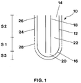
- Fig. 1 is a longitudinal section of a reactor tube according to a specific embodiment of the invention; and
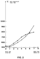
- Fig. 2 shows the wall temperature profile obtained in the reactor tube of Fig. 1 compared to the profile obtained in a bayonet reactor tube with maximum flow along the entire wall of the outer reactor tube.
- Fig. 1 shows in simplified form a longitudinal section of a bayonet tube heat exchange reactor according to the invention. The bayonet tube
heat exchange reactor 10 consists of anouter tube 12, which is open at itsinlet end 14 and closed at itsoutlet end 16. Within theouter tube 12 is arranged aninner tube 18 coaxially spaced apart theouter tube 12.Inner tube 18 is open at both ends. -
Reactor tube 10 is further provided withsleeve 24, which completely surrounds the external surface ofouter tube 12.Sleeve 24 encloses aspace 26 between the external surface ofouter tube 12 andsleeve 24. Space 26 provides a conduit for a heat conducting medium, which is supplied throughperforations 28 in section S1 ofsleeve 24 as further described below. Perforated section S1 extends over a certain length insleeve 24 within a region betweenoutlet end 16 and inletend 14 oftube 12. - Process gas is introduced into
reactor 10 throughopen end 14 ofouter tube 12. The process gas is then passed throughcatalyst 22 arranged between the walls ofouter tube 12 andinner tube 18. Having passed throughcatalyst 22 the gas impinges on the tube wall at outertube outlet end 16, where it reverses its direction toinner tube 18, through which the stream is withdrawn as a product stream. - Cooling or heating of the process stream in
catalyst 22 is obtained by a heat conducting medium being supplied tospace 26 throughperforations 28 insleeve 24. - The heat conducting medium is introduced over a large area onto the external surface in the lower part of
tube 12 through perforated section S1 insleeve 24 and flows withinspace 26 alongtube 12 in counterflow and indirect heat exchange with the process gas in the tube. - The medium flow increases in
space 26 within section S1 by progressively supply of the medium throughperforations 28. The medium flow reaches its maximum within region S2 inspace 26 adjacent and near theinlet end 14 oftube 12. - In the critical region S3 at the outlet end 16 of
tube 12 heat exchange between the heat conduction medium and the process stream is limited to radiation in that substantially no medium flow and, consequently, no forced convection proceeds inspace 26 within region S3, which is screened by an unperforated section ofsleeve 24. - In the following the invention is applied in a computation model illustrating the advantage of the inventive process during the endothermic steam reforming of hydrocarbons by heat exchange with hot flue gas in the reactor described above with reference to Fig. 1.
- In the computation model the following dimensions of the reactor are assumed:
- Outer Tube:
- length 7 m,
internal diameter 120 mm
wall thickness 5 mm - Inner Tube:
- length 6.1 m
internal diameter 30 mm
wall thickness 5 mm - Sleeve:
- length 7 m
length of perforated section 3 m
length of unperforated section 4 m
with a perforation of 1.5 %
(diameter of perforations about 2 mm, 50 mm pitch)
length of sleeve and sections are as distance from the outlet end to the inlet end of the outer tube.
The sleeve is spaced 5 mm apart the external surface of the outer tube. - 132 Nm³/h of a hydrocarbon-steam process gas are introduced at an inlet temperature of 520°C into the outer tube of the reactor. By passage through a conventional nickel reforming catalyst arranged between the outer and inner tube of the reactor the temperature of the reacted gas is increased from the above 520°C to 800°C at the outlet end of the outer reactor tube. The gas leaves the reactor through the inner tube with an outlet temperature of 570°C after the gas has given up heat by indirect heat exchange with the reacting gas in the outer tube. Further heat to the reacting gas is supplied by hot flue gas from a burner. The flue gas is supplied at 235 Nm³/h with an inlet temperature of 1300°C to the sleeve. The gas enters at substantially the same temperature the flue gas conduit between the sleeve end the exterior surface of the outer tube through the perforated section in the sleeve extending over a region of 3 meters from the outlet end of the tube. Inside the conduit the hot gas flows in counterflow and indirect heat exchange with the process gas in the outer tube of the reactor. After having supplied heat to the process gas the flue gas leaves the sleeve adjacent to the inlet end of the outer tube with an outlet temperature of 620°C.
- The heat flux at the outlet end of the outer tube is by the above process reduced from about 70.000 kcal/m² hr as in a corresponding reactor tube without the sleeve to about 20.000 kcal/m² hr in the reactor tube screened by the sleeve. Within the region of the perforated section in the sleeve the heat flux increases from the above 20.000 kcal/m² hr almost linearly to about 35.000 kcal/m² hr, because of the progressive supply of hot flue gas through the perforations in the sleeve. Corresponding values for the reactor without the sleeve and with maximum supply of flue gas in this region show a linear decrease from 70.000 kcal/m² hr at the outlet end to about 23.000 kcal/m² hr within a distance of 3 meters from the outlet end of the reactor tube.
- The temperature profile obtained in the wall of the outer reactor tube by the inventive process is further shown in Fig. 2 in comparison to the temperature profile obtained in a reactor tube similar to that of Fig. 1, but without
sleve 24, and thus with a maximum supply of flue gas in the region around the tube outlet end. - As apparent from Fig. 2 the wall temperature (O) at the tube outlet end, which is screened by an unperforated section of the sleeve is about 100°C lower than the wall temperature (X) of the tube without such screening. In the region adjacent to the outlet end, which is surrounded by the perforated part of the sleeve, the axial wall temperature gradient is flattened due to the progressive supply of hot flue gas within this region resulting in less extensive heating of tube wall around its outlet end and, consequently, in a prolonged lifetime of the tube. As an example the lifetime of a HK40 tube with an outer diameter of 120°C mm and inner diameter of 110 mm would be increased from 8.4·10⁵ to 9.4·10⁷ hours by decreasing the wall temperature from 850°C to 750°C.
Claims (9)
- In a process for carrying out non-adiabatic catalytic reactions in a tubular heat exchange reactor by indirect heat exchange between a process stream and a heat conducting medium, when passing the process stream through the reactor tube in counterflow with the heat conducting medium flowing externally along the reactor tube, the improvement comprises progressively supplying the medium to the reactor tube in increasing amounts from a region close to the outlet end to a region between the outlet end and the inlet end of the tube and, thereby, obtaining a reduced wall temperature at the outlet end of the tube.
- The process of claim 1, wherein the non-adiabatic catalytic reactions proceed exothermically in indirect heat exchange with a cooling medium as the heat conducting medium.
- The process of claim 1, wherein the non-adiabatic catalytic reactions proceed endothermically in indirect heat exchange with a heat transferring medium as the heat conducting medium.
- The process of claim 3, wherein the endothermic reactions comprise the steam reforming of hydrocarbons.
- The process of claim 1, wherein the amount of the heat conducting medium is increased from about zero at the outlet end to a maximum value at the inlet end of the reactor tube.
- A bayonet tube heat exchange reactor comprising an outer tube with an inlet end and a closed outlet end, an inner tube coaxially arranged within the outer tube and spaced apart the outer tube, and a catalyst within an annular space confined between the outer and inner tube, which reactor being provided with a sleeve externally surrounding the outer tube and confining a conduit for passage of a heat conducting medium between the sleeve and the outer tube, the sleeve having a plurality of perforations over a certain length thereof extending from a region close to the outlet end to a region between the outlet end and the inlet end of the outer tube;
whereby the heat conducting medium being progressively supplied to the conduit through the perforated length of the sleeve and flowing along the external surface of the outer tube in counterflow and indirect heat exchange with a process steam through the catalyst in the annular space between the outer and inner tube of the reactor. - The reactor of claim 6, wherein the perforated length of the sleeve constitutes of between 5 and 75%, preferably of between 10 and 50% of the length of the sleeve extending from the outlet end to the inlet end of the outer tube.
- The reactor of claim 6, wherein the sleeve is further provided with a plurality of perforations in a region surrounding the outlet end of the outer tube.
- The reactor of claim 6, wherein the width of the conduit confined between the sleeve and the outer tube is of between 0.01 and 0.08, preferably of between 0.02 and 0.05 times of the internal diameter of the outer tube.
Applications Claiming Priority (2)
| Application Number | Priority Date | Filing Date | Title |
|---|---|---|---|
| DK162891A DK162891A (en) | 1991-09-23 | 1991-09-23 | PROCEDURE AND REACTOR FOR IMPLEMENTING NON-ADIABATIC REACTIONS. |
| DK1628/91 | 1991-09-23 |
Publications (2)
| Publication Number | Publication Date |
|---|---|
| EP0535505A1 true EP0535505A1 (en) | 1993-04-07 |
| EP0535505B1 EP0535505B1 (en) | 1997-07-30 |
Family
ID=8106683
Family Applications (1)
| Application Number | Title | Priority Date | Filing Date |
|---|---|---|---|
| EP92116197A Expired - Lifetime EP0535505B1 (en) | 1991-09-23 | 1992-09-22 | Reactor for carrying out non-adiabatic catalytic reactions |
Country Status (9)
| Country | Link |
|---|---|
| EP (1) | EP0535505B1 (en) |
| JP (1) | JP3262354B2 (en) |
| KR (1) | KR100253064B1 (en) |
| AT (1) | ATE156030T1 (en) |
| AU (1) | AU652666B2 (en) |
| CA (1) | CA2078825C (en) |
| DE (1) | DE69221241T2 (en) |
| DK (1) | DK162891A (en) |
| NO (1) | NO178817C (en) |
Cited By (16)
| Publication number | Priority date | Publication date | Assignee | Title |
|---|---|---|---|---|
| EP0876993A1 (en) * | 1997-05-05 | 1998-11-11 | Haldor Topsoe A/S | Process and process unit for the preparation of ammonia synthesis gas |
| EP1063008A2 (en) * | 1999-05-28 | 2000-12-27 | Haldor Topsoe A/S | Reactor for carrying out a non-adiabatic process |
| WO2009156085A3 (en) * | 2008-06-26 | 2010-08-26 | Haldor Topsøe A/S | Process for the production of ammonia and stream superheater |
| JP2013517213A (en) * | 2010-01-19 | 2013-05-16 | ハルドール・トプサー・アクチエゼルスカベット | Method and apparatus for reforming hydrocarbons |
| WO2021043750A1 (en) | 2019-09-03 | 2021-03-11 | Haldor Topsøe A/S | Reformer furnace with supported reformer tubes |
| WO2021180805A1 (en) | 2020-03-13 | 2021-09-16 | Haldor Topsøe A/S | Process and plant for producing hydrocarbons with reduced co2-footprint and improved hydrogen integration |
| WO2022008248A1 (en) | 2020-07-06 | 2022-01-13 | Haldor Topsøe A/S | Regenerating the catalytic activity of a spent catalyst |
| WO2022034184A1 (en) | 2020-08-13 | 2022-02-17 | Haldor Topsøe A/S | Process and plant for producing gasoline from a renewable feed |
| WO2022034181A1 (en) | 2020-08-13 | 2022-02-17 | Haldor Topsøe A/S | Process and plant for producing gasoline from a tar-containing feed |
| WO2022152896A1 (en) | 2021-01-18 | 2022-07-21 | Topsoe A/S | Process and plant for producing hydrocarbons from a solid renewable feedstock with reduced co2-footprint |
| WO2022171643A1 (en) | 2021-02-09 | 2022-08-18 | Topsoe A/S | Process and plant for producing e-fuels |
| WO2022189560A1 (en) | 2021-03-11 | 2022-09-15 | Topsoe A/S | Method and system for producing hydrogen from ammonia cracking |
| WO2022218854A1 (en) | 2021-04-13 | 2022-10-20 | Topsoe A/S | Reduced metal dusting in bayonet reformer |
| WO2023275049A1 (en) | 2021-06-29 | 2023-01-05 | Topsoe A/S | Process and plant for producing methane or methanol from a solid renewable feedstock |
| WO2023084084A1 (en) | 2021-11-15 | 2023-05-19 | Topsoe A/S | Blue hydrogen process and plant |
| WO2023247316A1 (en) | 2022-06-20 | 2023-12-28 | Topsoe A/S | Conversion of carbon oxides to sustainable aviation fuel (saf) |
Families Citing this family (3)
| Publication number | Priority date | Publication date | Assignee | Title |
|---|---|---|---|---|
| CA2327419C (en) * | 1999-12-15 | 2009-01-13 | Uop Llc | Combinatorial catalytic reactor |
| FR2961117B1 (en) * | 2010-06-11 | 2012-06-08 | Inst Francais Du Petrole | REACTOR EXCHANGER TUBES BAIONNETTES AND A TUBE OF SMOKE SUSPENDED TO THE SUPERIOR REACTOR OF THE REACTOR |
| KR102603055B1 (en) * | 2022-12-22 | 2023-11-16 | 한국기계연구원 | Heating and cooling system using immersion cooling and heating and cooling method using immersion cooling |
Citations (2)
| Publication number | Priority date | Publication date | Assignee | Title |
|---|---|---|---|---|
| US1826548A (en) * | 1926-07-24 | 1931-10-06 | Selden Co | Catalytic apparatus |
| GB2150041A (en) * | 1983-11-14 | 1985-06-26 | Mitsubishi Heavy Ind Ltd | Double pipe exothermic reactor |
Family Cites Families (1)
| Publication number | Priority date | Publication date | Assignee | Title |
|---|---|---|---|---|
| JPS61111135A (en) * | 1984-11-07 | 1986-05-29 | Toshiba Corp | Reformer apparatus |
-
1991
- 1991-09-23 DK DK162891A patent/DK162891A/en not_active Application Discontinuation
- 1991-12-20 JP JP33898791A patent/JP3262354B2/en not_active Expired - Lifetime
-
1992
- 1992-09-22 CA CA002078825A patent/CA2078825C/en not_active Expired - Lifetime
- 1992-09-22 EP EP92116197A patent/EP0535505B1/en not_active Expired - Lifetime
- 1992-09-22 AT AT92116197T patent/ATE156030T1/en active
- 1992-09-22 NO NO923683A patent/NO178817C/en not_active IP Right Cessation
- 1992-09-22 DE DE69221241T patent/DE69221241T2/en not_active Expired - Lifetime
- 1992-09-22 AU AU25293/92A patent/AU652666B2/en not_active Expired
- 1992-09-23 KR KR1019920017315A patent/KR100253064B1/en not_active IP Right Cessation
Patent Citations (2)
| Publication number | Priority date | Publication date | Assignee | Title |
|---|---|---|---|---|
| US1826548A (en) * | 1926-07-24 | 1931-10-06 | Selden Co | Catalytic apparatus |
| GB2150041A (en) * | 1983-11-14 | 1985-06-26 | Mitsubishi Heavy Ind Ltd | Double pipe exothermic reactor |
Non-Patent Citations (2)
| Title |
|---|
| PATENT ABSTRACTS OF JAPAN vol. 10, no. 123 (C-344)5 May 1986 & JP-A-60 248 230 ( BABCOCK HITACHI K.K. ) 7 December 1985 * |
| PATENT ABSTRACTS OF JAPAN vol. 10, no. 292 (C-376)3 October 1986 & JP-A-61 111 135 ( TOSHIBA CORP. ) 29 May 1986 * |
Cited By (20)
| Publication number | Priority date | Publication date | Assignee | Title |
|---|---|---|---|---|
| EP0876993A1 (en) * | 1997-05-05 | 1998-11-11 | Haldor Topsoe A/S | Process and process unit for the preparation of ammonia synthesis gas |
| EP1063008A2 (en) * | 1999-05-28 | 2000-12-27 | Haldor Topsoe A/S | Reactor for carrying out a non-adiabatic process |
| EP1063008A3 (en) * | 1999-05-28 | 2001-03-28 | Haldor Topsoe A/S | Reactor for carrying out a non-adiabatic process |
| WO2009156085A3 (en) * | 2008-06-26 | 2010-08-26 | Haldor Topsøe A/S | Process for the production of ammonia and stream superheater |
| US8261700B2 (en) | 2008-06-26 | 2012-09-11 | Haldor Topsoe A/S | Steam superheater |
| JP2013517213A (en) * | 2010-01-19 | 2013-05-16 | ハルドール・トプサー・アクチエゼルスカベット | Method and apparatus for reforming hydrocarbons |
| US9227844B2 (en) | 2010-01-19 | 2016-01-05 | Haldor Topsoe A/S | Heat exchange reformer with double-tubes for reforming hydrocarbons |
| US11918991B2 (en) | 2019-09-03 | 2024-03-05 | Haldor Topsøe A/S | Reformer furnace with supported reformer tubes |
| WO2021043750A1 (en) | 2019-09-03 | 2021-03-11 | Haldor Topsøe A/S | Reformer furnace with supported reformer tubes |
| WO2021180805A1 (en) | 2020-03-13 | 2021-09-16 | Haldor Topsøe A/S | Process and plant for producing hydrocarbons with reduced co2-footprint and improved hydrogen integration |
| WO2022008248A1 (en) | 2020-07-06 | 2022-01-13 | Haldor Topsøe A/S | Regenerating the catalytic activity of a spent catalyst |
| WO2022034184A1 (en) | 2020-08-13 | 2022-02-17 | Haldor Topsøe A/S | Process and plant for producing gasoline from a renewable feed |
| WO2022034181A1 (en) | 2020-08-13 | 2022-02-17 | Haldor Topsøe A/S | Process and plant for producing gasoline from a tar-containing feed |
| WO2022152896A1 (en) | 2021-01-18 | 2022-07-21 | Topsoe A/S | Process and plant for producing hydrocarbons from a solid renewable feedstock with reduced co2-footprint |
| WO2022171643A1 (en) | 2021-02-09 | 2022-08-18 | Topsoe A/S | Process and plant for producing e-fuels |
| WO2022189560A1 (en) | 2021-03-11 | 2022-09-15 | Topsoe A/S | Method and system for producing hydrogen from ammonia cracking |
| WO2022218854A1 (en) | 2021-04-13 | 2022-10-20 | Topsoe A/S | Reduced metal dusting in bayonet reformer |
| WO2023275049A1 (en) | 2021-06-29 | 2023-01-05 | Topsoe A/S | Process and plant for producing methane or methanol from a solid renewable feedstock |
| WO2023084084A1 (en) | 2021-11-15 | 2023-05-19 | Topsoe A/S | Blue hydrogen process and plant |
| WO2023247316A1 (en) | 2022-06-20 | 2023-12-28 | Topsoe A/S | Conversion of carbon oxides to sustainable aviation fuel (saf) |
Also Published As
| Publication number | Publication date |
|---|---|
| JPH0576748A (en) | 1993-03-30 |
| ATE156030T1 (en) | 1997-08-15 |
| EP0535505B1 (en) | 1997-07-30 |
| AU652666B2 (en) | 1994-09-01 |
| JP3262354B2 (en) | 2002-03-04 |
| DK162891D0 (en) | 1991-09-23 |
| KR930005665A (en) | 1993-04-20 |
| CA2078825C (en) | 2000-12-05 |
| KR100253064B1 (en) | 2000-04-15 |
| NO923683D0 (en) | 1992-09-22 |
| NO178817C (en) | 1996-06-12 |
| DK162891A (en) | 1993-03-24 |
| NO178817B (en) | 1996-03-04 |
| NO923683L (en) | 1993-03-24 |
| DE69221241D1 (en) | 1997-09-04 |
| AU2529392A (en) | 1993-03-25 |
| CA2078825A1 (en) | 1993-03-24 |
| DE69221241T2 (en) | 1997-11-27 |
Similar Documents
| Publication | Publication Date | Title |
|---|---|---|
| EP0535505B1 (en) | Reactor for carrying out non-adiabatic catalytic reactions | |
| US5429809A (en) | Process and reactor for carrying out non-adiabatic catalytic reactions | |
| EP0194067B2 (en) | Steam reforming hydrocarbons | |
| US4650651A (en) | Integrated process and apparatus for the primary and secondary catalytic steam reforming of hydrocarbons | |
| US7731935B2 (en) | Steam reforming | |
| EP0440258B1 (en) | Heat exchange reforming process and reactor system | |
| AU2003248394B2 (en) | Process and apparatus for the preparation of synthesis gas | |
| RU2618022C2 (en) | Tube for reforming with internal heat exchange | |
| AU2003248392B2 (en) | Process and apparatus for the preparation of synthesis gas | |
| KR20060048125A (en) | Heat exchange process and reactor | |
| WO2006117572A1 (en) | Apparatus and process for steam reforming of hydrocarbons | |
| US11192081B2 (en) | Bayonet catalytic reactor | |
| CN109310971B (en) | Reactor for producing synthesis gas by steam reforming | |
| GB1603703A (en) | Methanation process | |
| JPS59102816A (en) | Ammonia converter | |
| US11918991B2 (en) | Reformer furnace with supported reformer tubes | |
| US20240035758A1 (en) | Heat exchange reactor seal apparatus | |
| CA2310482A1 (en) | Reactor for carrying out a non-adiabatic process |
Legal Events
| Date | Code | Title | Description |
|---|---|---|---|
| PUAI | Public reference made under article 153(3) epc to a published international application that has entered the european phase |
Free format text: ORIGINAL CODE: 0009012 |
|
| AK | Designated contracting states |
Kind code of ref document: A1 Designated state(s): AT BE CH DE FR GB IE IT LI NL SE |
|
| RBV | Designated contracting states (corrected) |
Designated state(s): AT BE CH DE FR GB IT LI NL SE |
|
| 17P | Request for examination filed |
Effective date: 19930915 |
|
| 17Q | First examination report despatched |
Effective date: 19941115 |
|
| GRAG | Despatch of communication of intention to grant |
Free format text: ORIGINAL CODE: EPIDOS AGRA |
|
| GRAH | Despatch of communication of intention to grant a patent |
Free format text: ORIGINAL CODE: EPIDOS IGRA |
|
| GRAH | Despatch of communication of intention to grant a patent |
Free format text: ORIGINAL CODE: EPIDOS IGRA |
|
| GRAA | (expected) grant |
Free format text: ORIGINAL CODE: 0009210 |
|
| AK | Designated contracting states |
Kind code of ref document: B1 Designated state(s): AT BE CH DE FR GB IT LI NL SE |
|
| REF | Corresponds to: |
Ref document number: 156030 Country of ref document: AT Date of ref document: 19970815 Kind code of ref document: T |
|
| REG | Reference to a national code |
Ref country code: CH Ref legal event code: NV Representative=s name: PATENTANWALTSBUERO JEAN HUNZIKER Ref country code: CH Ref legal event code: EP |
|
| REF | Corresponds to: |
Ref document number: 69221241 Country of ref document: DE Date of ref document: 19970904 |
|
| ET | Fr: translation filed | ||
| PLBE | No opposition filed within time limit |
Free format text: ORIGINAL CODE: 0009261 |
|
| STAA | Information on the status of an ep patent application or granted ep patent |
Free format text: STATUS: NO OPPOSITION FILED WITHIN TIME LIMIT |
|
| 26N | No opposition filed | ||
| PGFP | Annual fee paid to national office [announced via postgrant information from national office to epo] |
Ref country code: SE Payment date: 20000921 Year of fee payment: 9 |
|
| PG25 | Lapsed in a contracting state [announced via postgrant information from national office to epo] |
Ref country code: SE Free format text: LAPSE BECAUSE OF NON-PAYMENT OF DUE FEES Effective date: 20010923 |
|
| REG | Reference to a national code |
Ref country code: GB Ref legal event code: IF02 |
|
| EUG | Se: european patent has lapsed |
Ref document number: 92116197.2 |
|
| PGFP | Annual fee paid to national office [announced via postgrant information from national office to epo] |
Ref country code: DE Payment date: 20100929 Year of fee payment: 19 |
|
| PGFP | Annual fee paid to national office [announced via postgrant information from national office to epo] |
Ref country code: IT Payment date: 20100928 Year of fee payment: 19 |
|
| PGFP | Annual fee paid to national office [announced via postgrant information from national office to epo] |
Ref country code: CH Payment date: 20110926 Year of fee payment: 20 |
|
| PGFP | Annual fee paid to national office [announced via postgrant information from national office to epo] |
Ref country code: FR Payment date: 20111005 Year of fee payment: 20 Ref country code: AT Payment date: 20110901 Year of fee payment: 20 Ref country code: GB Payment date: 20110926 Year of fee payment: 20 |
|
| PGFP | Annual fee paid to national office [announced via postgrant information from national office to epo] |
Ref country code: NL Payment date: 20110929 Year of fee payment: 20 |
|
| PGFP | Annual fee paid to national office [announced via postgrant information from national office to epo] |
Ref country code: BE Payment date: 20110927 Year of fee payment: 20 |
|
| REG | Reference to a national code |
Ref country code: DE Ref legal event code: R071 Ref document number: 69221241 Country of ref document: DE |
|
| REG | Reference to a national code |
Ref country code: DE Ref legal event code: R071 Ref document number: 69221241 Country of ref document: DE |
|
| REG | Reference to a national code |
Ref country code: CH Ref legal event code: PL |
|
| BE20 | Be: patent expired |
Owner name: *HALDOR TOPSOE A/S Effective date: 20120922 |
|
| REG | Reference to a national code |
Ref country code: NL Ref legal event code: V4 Effective date: 20120922 |
|
| REG | Reference to a national code |
Ref country code: GB Ref legal event code: PE20 Expiry date: 20120921 |
|
| PG25 | Lapsed in a contracting state [announced via postgrant information from national office to epo] |
Ref country code: DE Free format text: LAPSE BECAUSE OF EXPIRATION OF PROTECTION Effective date: 20120925 Ref country code: GB Free format text: LAPSE BECAUSE OF EXPIRATION OF PROTECTION Effective date: 20120921 |
|
| REG | Reference to a national code |
Ref country code: AT Ref legal event code: MK07 Ref document number: 156030 Country of ref document: AT Kind code of ref document: T Effective date: 20120922 |