EP0534671A2 - Phenolic graphite donor roll - Google Patents
Phenolic graphite donor roll Download PDFInfo
- Publication number
- EP0534671A2 EP0534671A2 EP92308462A EP92308462A EP0534671A2 EP 0534671 A2 EP0534671 A2 EP 0534671A2 EP 92308462 A EP92308462 A EP 92308462A EP 92308462 A EP92308462 A EP 92308462A EP 0534671 A2 EP0534671 A2 EP 0534671A2
- Authority
- EP
- European Patent Office
- Prior art keywords
- roll
- printer
- donor
- toner
- particles
- Prior art date
- Legal status (The legal status is an assumption and is not a legal conclusion. Google has not performed a legal analysis and makes no representation as to the accuracy of the status listed.)
- Granted
Links
Images


Classifications
-
- G—PHYSICS
- G03—PHOTOGRAPHY; CINEMATOGRAPHY; ANALOGOUS TECHNIQUES USING WAVES OTHER THAN OPTICAL WAVES; ELECTROGRAPHY; HOLOGRAPHY
- G03G—ELECTROGRAPHY; ELECTROPHOTOGRAPHY; MAGNETOGRAPHY
- G03G15/00—Apparatus for electrographic processes using a charge pattern
- G03G15/06—Apparatus for electrographic processes using a charge pattern for developing
- G03G15/08—Apparatus for electrographic processes using a charge pattern for developing using a solid developer, e.g. powder developer
- G03G15/0806—Apparatus for electrographic processes using a charge pattern for developing using a solid developer, e.g. powder developer on a donor element, e.g. belt, roller
- G03G15/0818—Apparatus for electrographic processes using a charge pattern for developing using a solid developer, e.g. powder developer on a donor element, e.g. belt, roller characterised by the structure of the donor member, e.g. surface properties
Definitions
- the present invention is generally directed to electrostatographic printers and, more specifically, to donor rolls for use in such printers.
- toner particles are deposited on an electrostatic latent image present on an insulating surface, such as selenium, utilizing, for example, cascade development, magnetic brush development, powder cloud development, and touchdown development.
- cascade development magnetic brush development
- powder cloud development powder cloud development
- conductive toner particles are selected, and imagewise toner deposition onto the photoconductive member is obtained by induction charging of the toner particles. Electrostatic transfer of conductive toner particles to plain bond paper is, however, usually inefficient as the charge on the toner particles can be reversed by induction charging from the paper during the transfer step. Accordingly, electrophotographic systems wherein conductive single component toner particles are used can require a special overcoated insulating paper to achieve sufficient electrostatic toner transfer.
- developing rollers are known which are formed by pouring or spraying a solvent/resin/conductive particle solution. The volatile portion of the solution is evaporated leaving a resin/conductive particle substrate for use in a developer roller.
- the present invention provides an electrostatographic printer comprising a photoreceptor; charging means for creating a latent image on said photoreceptor; developer applying means for applying developer material to said photoreceptor; transfer means for transferring said applied developer material to a sheet of support material; wherein said developer applying means comprises a donor roll in a developer sump, the donor roll comprising a homogenous mixture of a thermoset and a conductor.
- the roll may be a seamless extruded, or centrifugally-cast, cylinder.
- the said thermoset is a phenolic resin and said conductor is particulate graphite.
- the roll may further comprise molybdenum disulfide as a lubricant.
- FIG. 1 schematically depicts the various elements of an illustrative electrophotographic printing machine incorporating a particular form of donor roll. It will become evident from the following discussion that this donor roll is equally well suited for use in a wide variety of printing machines and is not necessarily limited in its application to the particular machine depicted herein.
- the electrophotographic printing machine employs a belt 10 having a photoconductive surface 12 deposited on a conductive substrate 14.
- photoconductive surface 12 is made from a selenium alloy with conductive substrate 14 being made from a nickel alloy which is electrically grounded.
- Other suitable photoconductive surfaces and conductive substrates may also be employed.
- Belt 10 moves in the direction of arrow 16 to advance successive portions of photoconductive surface 12 through the various processing stations disposed about the path of movement thereof. As shown, belt 10 is entrained about rollers 18, 20, 22 and 24. Roller 24 is coupled to motor 26 which drives roller 24 so as to advance belt 10 in the direction of arrow 16. Rollers 18, 20 and 22 are idler rollers which rotate freely as belt 10 moves in the direction of arrow 16.
- a corona generating device indicated generally by the reference numeral 28, charges a portion of photoconductive surface 12 of belt 10 to a relatively high, substantially uniform potential.
- the charged portion of photoconductive surface 12 is advanced through exposure station B.
- an original document 30 is positioned face down upon a transparent platen 32.
- Lamps 34 flash light rays onto original document 30.
- the light rays reflected from original document 30 are transmitted through lens 36 forming a light image thereof.
- Lens 36 focuses the light image onto the charged portion of photoconductive surface 12 to selectively dissipate the charge thereon.
- This records an electrostatic latent image on photoconductive surface 12 which corresponds to informational areas contained within original document 30 disposed upon transparent platen 32.
- belt 10 advances the electrostatic latent image recorded on photoconductive surface 12 to development station C.
- a developer unit transports a single component developer material of toner particles into contact with or in close proximity to the electrostatic latent image recorded on photoconductive surface 12. Toner particles are attracted to the electrostatic latent image forming a toner powder image on photoconductive surface 12 of belt 10 so as to develop the electrostatic latent image.
- the detailed structure of developer unit 38 will be described hereinafter with reference to Figure 2.
- sheet feeding apparatus 48 includes a feed roll 50 contacting the upper most sheet of a stack of sheets 52. Feed roll 50 rotates to advance the upper most sheet from stack 50 into chute 54. Chute 54 directs the advancing sheet of support material 46 into contact with photoconductive surface 12 of belt 10 in a timed sequence so that the toner powder image developed thereon contacts the advancing sheet of support material at transfer station D.
- Transfer station D includes a corona generating device 56 which sprays ions onto the backside of sheet 46. This attracts the toner powder image from photoconductive surface 12 to sheet 46. After transfer, the sheet continues to move in the direction of arrow 58 onto a conveyor 60 which moves the sheet to fusing station E.
- Fusing station E includes a fuser assembly, indicated generally by the reference numeral 62, which permanently affixes the powder image to sheet 46.
- fuser assembly 62 includes a heated fuser roller 64 and a back-up roller 66 with the toner powder image contacting fuser roller 64. In this manner, the toner powder image is permanently affixed to sheet 46.
- chute 68 guides the advancing sheet to catch tray 70 for subsequent removal from the printing machine by the operator.
- Cleaning station F includes a pre-clean corona generating device (not shown) and a rotatably mounted fibrous brush 72 in contact with photoconductive surface 12.
- the pre-clean corona generator neutralizes the electrostatic charge attracting the particles to the photoconductive surface. These particles are cleaned from the photoconductive surface by the rotation of brush 72 in contact therewith.
- a discharge lamp (not shown) floods photoconductive surface 12 with light to dissipate any residual charge remaining thereon prior to the charging thereof for the next successive imaging cycle.
- the developer unit includes a donor roller 74.
- An electrical bias is applied to the donor roller.
- the electrical bias applied on the donor roller depends upon the background voltage level of the photoconductive surface, the characteristics of the donor roller, and the spacing between the donor roller and the photoconductive surface. It is thus clear that the electrical bias applied on the donor roller may vary widely.
- Donor roller 74 is coupled to a motor which rotates donor roller 74 in the direction of arrow 76.
- Donor roller 74 is positioned, at least partially, in chamber, or sump, 78 of housing 80.
- a toner mixer indicated generally by the reference numeral 44, mixes and fluidizes the toner particles.
- the fluidized toner particles seek their own level under the influence of gravity. Inasmuch as new toner particles are being discharge from container 86 into one end of the chamber 78 of housing 80, the force exerted on the fluidized toner particles by the new toner particles being added at that end moves the fluidized toner particles from that end of housing 80 to the other end thereof.
- Toner mixer 44 is an elongated member located in chamber 78 closely adjacent to an arcuate portion 84 of housing 80. Arcuate portion 84 is closely adjacent to elongated member 44 and wraps about a portion thereof.
- Voltage source 42 is electrically connected to elongated member 44 by control circuit 88.
- Voltage source 40 is connected to voltage source 42 and donor roll 74.
- Voltage sources 40 and 42 are DC voltage sources. This establishes an electrical bias between donor roll 74 and toner mixer 44 which ranges from about 260 volts to about 1000 volts. Preferably, an electrical bias of about 600 volts is applied between donor roller 74 and toner mixer 44.
- the current biasing the toner mixer is a measure of toner usage.
- Control circuit 88 detects the current biasing the toner mixer 44 and, in response thereto, generates a control signal. The control signal from control circuit 88 regulates the energization of motor 82.
- Toner mixer 44 is spaced from donor roller 74 to define a gap therebetween. This gap may range from about 0.05 centimeters to about 0.15 centimeters.
- Donor roller 74 rotates in the direction of arrow 76 to move the toner particles attracted thereto into contact with or in close proximity to the electrostatic latent image recorded on photoconductive surface 12 of belt 10.
- charging blade 92 has the region of the free end thereof resiliently urged into contact with donor roller 74.
- Charging blade 92 may be made from a metal, silicone rubber, or a plastic material.
- charging blade 92 may be made from steel phosphor bronze and ranges from about 0.025 millimeters to about 0.25 millimeters in thickness, being a maximum of 25 millimeters wide.
- the free end of the charging blade extends beyond the tangential contact point with donor roller 74 by about 4 millimeters or less.
- Charging blade 92 is maintained in contact with donor roller 74 at a pressure ranging from about 10 grams per centimeter to about 250 grams per centimeter.
- the toner particle layer adhering to donor roller 74 is charged to a maximum of 60 microcoulombs/gram with the toner mass adhering thereto ranging from about 0.1 milligrams per centimeter2 to about 2 milligrams per centimeter2 of roll surface.
- the charging function can, alternatively, be achieved by a rotating rod in contact with and axially parallel to the donor roll.
- a rotating rod in contact with and axially parallel to the donor roll.
- self spaced wires 102 are used to create a control led toner cloud near the surface of the photoreceptor 120.
- a blade 108 with a rotating charge rod 110 charges the toner particle layer supplied by the toner supply tube 106 onto the surface of donor roller 104.
- non magnetic toner is metered and charged on donor roll 104 by the small diameter rotating charge rod 110.
- Charge rod 110 rotates at a fraction of the surface speed of the donor roll and in the reverse direction. Toner is metered to a mono layer and tribocharged.
- Flexible electrodes such as corotron wires 102, are in self-spaced contact with the toned donor roll in the development nip gap. Low AC voltage applied between the wires and the donor roll breaks toner-donor adhesive bonds to form a localized cloud, while the DC image potential controls projection to the receiver.
- donor rollers can be made from aluminum, nickel or steel.
- donor rollers can be made of an anodized metal or a metal coated with a suitable material.
- a polytetrafluoroethylene based coating composition such as "Teflon”, a trademark of the Du Pont Corporation, or a polyvinylidene fluoride based resin, such as "Kynar”, a trademark of the Pennwalt Corporation, may be used to coat the metal roller.
- a coating acts to assist in charging the particles adhering to the surface thereof.
- Still another type of known donor roller is a stainless steel plated by a catalytic nickel generation process and impregnated with "Teflon".
- the surface of the donor roller can be roughened from a fraction of a micron to several microns, peak to peak.
- the donor roll for the Fig. 1 printing machine comprises a homogenous mixture of a thermoset and a conductor, and is made by an extrusion or centrifugal casting process.
- evaporative solvents in manufacturing the prior art donor rolls can cause a number of deficiencies in the donor rolls.
- the use of evaporative solvents is helpful for allowing the spraying, dipping or pouring of a resin, and the subsequent drying of the resin upon the evaporation of the solvent.
- the evaporation of the solvent creates voids within the resin which effect the quality of the donor roll when used in a printing process.
- the voids left by the evaporated solvent result in a discontinuity of particles in the resin binder, which in turn results in an electrical discontinuity of the donor roll.
- Areas deficient in conductive particles will lack development in those areas and result in an undesirable change in the image density.
- evaporative solvents also results in the settling of conductive particles such that an electrical gradient results in the donor roll.
- an electrical gradient which naturally results from spraying or pouring solvent/resin/conductive particle solutions is undesirable.
- the change in outer diameter results in a change in the electrical conductivity of the surface of the donor roller, thus resulting in lack of control of the surface conductivity.
- the donor roll for the Fig. 1 machine is made by centrifugal casting or extrusion to avoid the degradation in printed image quality due to evaporative solvents.
- a liquid curable thermoset resin having a conductive filler mixed therein is introduced into a rotating cylindrical mold and allowed to cure.
- a rigid drum is produced in the mold which matches the dimensional character and surface quality of the interior of the mold.
- a belt driven centrifugal mold 202 rests upon tooling plate 210 and is driven by air motor 208 on support flange 214.
- High speed ultra-precision bearings 204 allow mold 202 to rotate at high speed within bearing housing 206.
- the centrifugal casting method results in a donor roll having very tight dimensional tolerances equal to those of the mold.
- the donor roll is seamless and has excellent surface quality, low UMC, excellent mechanical properties, high temperature resistance and good solvent resistance.
- it is possible to homogeneously disperse conductive particles and at high loadings.
- the resin used is a thermoset resin.
- Extruded thermosets like centrifugally casted thermosets, have superior dimensional stability, outstanding heat resistance, and higher mechanical strengths.
- high pressure and a uniform melt history result in a highly cross-linked thermoset with improved uniformity.
- the high density roll made from an extrusion process has low porosity and thus improved electrical continuity.
- thermosets are phenolic, melamine, epoxy, DAP (diallyl phthalate resin), ureas, alkyds, and polyesters.
- Thermosets are cross-linked and have relatively low viscosities until they are cured.
- a thermoset is heat-hardenable, and once hardened will not remelt.
- Phenolics are relatively inexpensive, heat and flame resistant, dimensionally stable, and lend themselves well to compounding and easy molding. Phenolics are the preferred thermoset resin but other thermosets can be used.
- Melamine has a high resistance to scratches
- epoxy has good chemical resistance
- DAP has longterm dimensional stability
- polyesters have good electrical properties and are impact resistant.
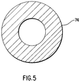
- Carbon particles such as fluorinated carbon or graphite particles, can be used as the conductive particulate. Also envisioned is the use of graphite particles mixed with other conductive particles which provide some lubricity in the extrusion process, such as zinc oxide, titanium oxide, tin oxide or molybdenum disulfide. As in Figure 5, the resulting phenolic resin/graphite extruded tube 74 is homogenous without any noticeable loading gradient after surface grinding.
- Thermoset tubes of approximately 26.6 millimeters outer diameter with an approximately 1 to 5 millimeter wall thickness can be made by casting or extruding.
- the conductive particles comprise from 6 to 25 weight % of the original particulate mixture, and preferably from approximately 6 to 15 weight % of the original mixture.
- the tube can be cut to the desired length.
- the inside diameter of each tube is preferably counterbored, with journals being press fitted into each end of the tube. Subsequently, the outside surface of the graphite loaded phenolic tube is surface ground to a final 25 millimeter outer diameter, with a wall thickness of approximately 1.6 millimeters at the journal ends.
- a straightness of approximately .025 millimeters and a runout of less than .05 millimeters can be achieved.
- the surface resistivity of the finish ground rolls should be preferably less than 1011 ohm.cm., and preferably from approximately 101 ohm.cm. to about 109 ohm.cm.
- a donor roll of the above-described dimensions weighs approximately 186 grams, in comparison to a similarly sized aluminum roll coated with Teflon which weighs approximately 352 grams, or in comparison to a typical phenolic roll with a solid steel shaft center which weighs 869 grams.
- Phenolic graphite rolls as in Figure 5 were tested in a developer housing and were compared to a Teflon-S coated aluminum roll and a phenolic roll fabricated with a solid steel shaft through the phenolic roll center (and having journals at each end) as controls.
- Test Roll Conditions Toner Materials Black toner made of 90% styrenebutadiene (available from Goodyear), 8% Regal 330 carbon black (available from Cabot Corp.), 2% dodecyldimethyl-ammonium sulfate (a toner charge control agent) + 1 % of a surface treated silica used as a flow aid.
- Roll Speeds Donor roll 8 in./sec., charge rod 4 in./sec., toner mover 15 in./sec.
- the test results were: Q/M ⁇ c/g mass/area (middle of roll) mg/cm2 mass/area (left side of roll) mg/cm2 mass/area (right side of roll) mg/cm2 Phenolic (15% Graphite) + 9.1 .45 .45 .41 Phenolic (20% Graphite) + 9.9 .49 .55 .49 Phenolic (25% Graphite) + 10.0 .39 .45 .60 Typical Teflon-S Coating Roll + 10.0 .36 .40 .38 Typical Phenolic Roll 9.4 .44 .45 .45
Abstract
Description
- The present invention is generally directed to electrostatographic printers and, more specifically, to donor rolls for use in such printers.
- The development of images by various methods, including electrostatographic means, is well known. In several of these methods, toner particles are deposited on an electrostatic latent image present on an insulating surface, such as selenium, utilizing, for example, cascade development, magnetic brush development, powder cloud development, and touchdown development. In view of several disadvantages associated with systems that use two-component developer material, considerable effort has been directed to designing processes which utilize toner particles only.
- In many of the single component development processes, conductive toner particles are selected, and imagewise toner deposition onto the photoconductive member is obtained by induction charging of the toner particles. Electrostatic transfer of conductive toner particles to plain bond paper is, however, usually inefficient as the charge on the toner particles can be reversed by induction charging from the paper during the transfer step. Accordingly, electrophotographic systems wherein conductive single component toner particles are used can require a special overcoated insulating paper to achieve sufficient electrostatic toner transfer. Furthermore, in single component processes with conductive toner particles the control of undesirable background, or background suppression, cannot usually be achieved with electrostatic forces as the toner particles are inductively charged, and deposited on the image bearing member, which is not the situation with two-component developer processes where control of background development is accomplished by electrostatic forces acting on the triboelectrically charged toner particles, causing these particles to be directed away from image bearing members.
- Recently, there has been disclosed an efficient, single component, economical, simple process, and apparatus for the development of latent electrostatic images wherein insulative, nonmagnetic, or color toner particles are appropriately charged; and there is obtained two-component image quality utilizing a single component development apparatus. In this system, as detailed hereinafter, and as described in U.S. Patent No. 4,459,009, there is selected a charging roll means which simultaneously meters and charges toner particles. A donor electrode serves to transport the toner particles, which electrode can be comprised of numerous suitable materials, including for example, aluminized Mylar overcoated with a polymer containing carbon black, electroformed nickel, or a carbon black loaded extruded polymer. However, there continues to be a need for donor rolls with improved characteristics for applying toner to charged photoreceptors.
- Furthermore, known prior art donor rolls using materials such as Krylon, available from Borden, Inc., coated onto a nickel substrate, although suitable for their intended purposes are not scratch resistant over extended time periods. Thus, these coatings permit scratches to form on the toner transporting means, which in turn adversely affects image copy quality. Additionally, toner particles appear to permanently adhere to the surface of transporting members with Krylon coatings which adhesion results in undesirable high background deposits on the resulting developed images.
- It is also known to form a developing member incorporating a dielectric material in which conductive particles are dispersed. As described in U.S. Patent No. 4,990,963 to Yamamoto et al., developing rollers are known which are formed by pouring or spraying a solvent/resin/conductive particle solution. The volatile portion of the solution is evaporated leaving a resin/conductive particle substrate for use in a developer roller.
- It is an object of the present invention to provide a donor roll having improved characteristics for use in an electrostatographic printer.
- The present invention provides an electrostatographic printer comprising a photoreceptor; charging means for creating a latent image on said photoreceptor; developer applying means for applying developer material to said photoreceptor; transfer means for transferring said applied developer material to a sheet of support material; wherein said developer applying means comprises a donor roll in a developer sump, the donor roll comprising a homogenous mixture of a thermoset and a conductor. The roll may be a seamless extruded, or centrifugally-cast, cylinder. Preferably, the said thermoset is a phenolic resin and said conductor is particulate graphite. The roll may further comprise molybdenum disulfide as a lubricant.
- By way of example only, an embodiment of the invention will be described with reference to the accompanying drawings, in which:
- Figure 1 is a schematic elevational view depicting an electrophotographic printing machine incorporating a donor roll, in accordance with the present invention;
- Figure 2 is a schematic elevational view showing the development apparatus used in the Figure 1 printing machine;
- Figure 3 is a schematic elevational view showing an alternative development apparatus to that shown in Figure 2;
- Figure 4 is a view of a centrifugal casting apparatus for forming the donor roll of the printing machine; and
- Figure 5 is a cross sectional view of the extruded or cast donor roll.
- In the drawings, like reference numerals have been throughout to designate identical elements. Figure 1 schematically depicts the various elements of an illustrative electrophotographic printing machine incorporating a particular form of donor roll. It will become evident from the following discussion that this donor roll is equally well suited for use in a wide variety of printing machines and is not necessarily limited in its application to the particular machine depicted herein.
- Inasmuch as the art of electrophotographic printing is well known, the various processing stations employed in the Figure 1 printing machine are shown schematically and their operation will be described briefly with reference thereto.
- Turning now to Figure 1, the electrophotographic printing machine employs a
belt 10 having aphotoconductive surface 12 deposited on aconductive substrate 14. Preferably,photoconductive surface 12 is made from a selenium alloy withconductive substrate 14 being made from a nickel alloy which is electrically grounded. Other suitable photoconductive surfaces and conductive substrates may also be employed.Belt 10 moves in the direction ofarrow 16 to advance successive portions ofphotoconductive surface 12 through the various processing stations disposed about the path of movement thereof. As shown,belt 10 is entrained aboutrollers Roller 24 is coupled tomotor 26 which drivesroller 24 so as to advancebelt 10 in the direction ofarrow 16.Rollers belt 10 moves in the direction ofarrow 16. - Initially, a portion of
belt 10 passes through charging station A. At charging station A, a corona generating device, indicated generally by thereference numeral 28, charges a portion ofphotoconductive surface 12 ofbelt 10 to a relatively high, substantially uniform potential. - Next, the charged portion of
photoconductive surface 12 is advanced through exposure station B. At exposure station B, anoriginal document 30 is positioned face down upon atransparent platen 32.Lamps 34 flash light rays ontooriginal document 30. The light rays reflected fromoriginal document 30 are transmitted throughlens 36 forming a light image thereof.Lens 36 focuses the light image onto the charged portion ofphotoconductive surface 12 to selectively dissipate the charge thereon. This records an electrostatic latent image onphotoconductive surface 12 which corresponds to informational areas contained withinoriginal document 30 disposed upontransparent platen 32. Thereafter, belt 10 advances the electrostatic latent image recorded onphotoconductive surface 12 to development station C. - At development station C, a developer unit, indicated generally by the
reference numeral 38, transports a single component developer material of toner particles into contact with or in close proximity to the electrostatic latent image recorded onphotoconductive surface 12. Toner particles are attracted to the electrostatic latent image forming a toner powder image onphotoconductive surface 12 ofbelt 10 so as to develop the electrostatic latent image. The detailed structure ofdeveloper unit 38 will be described hereinafter with reference to Figure 2. - After development, belt 10 advances the toner powder image to transfer station D. At transfer station D, a sheet of
support material 46 is moved into contact with the toner powder image.Support material 46 is advanced to transfer station D by a sheet feeding apparatus, indicated generally by thereference numeral 48. Preferably,sheet feeding apparatus 48 includes afeed roll 50 contacting the upper most sheet of a stack ofsheets 52.Feed roll 50 rotates to advance the upper most sheet fromstack 50 intochute 54.Chute 54 directs the advancing sheet ofsupport material 46 into contact withphotoconductive surface 12 ofbelt 10 in a timed sequence so that the toner powder image developed thereon contacts the advancing sheet of support material at transfer station D. - Transfer station D includes a
corona generating device 56 which sprays ions onto the backside ofsheet 46. This attracts the toner powder image fromphotoconductive surface 12 tosheet 46. After transfer, the sheet continues to move in the direction ofarrow 58 onto aconveyor 60 which moves the sheet to fusing station E. - Fusing station E includes a fuser assembly, indicated generally by the
reference numeral 62, which permanently affixes the powder image tosheet 46. Preferably,fuser assembly 62 includes a heatedfuser roller 64 and a back-up roller 66 with the toner powder image contactingfuser roller 64. In this manner, the toner powder image is permanently affixed tosheet 46. After fusing,chute 68 guides the advancing sheet to catchtray 70 for subsequent removal from the printing machine by the operator. - Invariably, after the sheet of support material is separated from
photoconductive surface 12 ofbelt 10, some residual particles remain adhering thereto. These residual particles are removed fromphotoconductive surface 12 at cleaning station F. Cleaning station F includes a pre-clean corona generating device (not shown) and a rotatably mountedfibrous brush 72 in contact withphotoconductive surface 12. The pre-clean corona generator neutralizes the electrostatic charge attracting the particles to the photoconductive surface. These particles are cleaned from the photoconductive surface by the rotation ofbrush 72 in contact therewith. Subsequent to cleaning, a discharge lamp (not shown) floodsphotoconductive surface 12 with light to dissipate any residual charge remaining thereon prior to the charging thereof for the next successive imaging cycle. - The foregoing description is sufficient to illustrate the general operation of the electrophotographic printing machine.
- Referring now to Figure 2, the detailed structure of
developer unit 38 is shown. The developer unit includes adonor roller 74. An electrical bias is applied to the donor roller. The electrical bias applied on the donor roller depends upon the background voltage level of the photoconductive surface, the characteristics of the donor roller, and the spacing between the donor roller and the photoconductive surface. It is thus clear that the electrical bias applied on the donor roller may vary widely.Donor roller 74 is coupled to a motor which rotatesdonor roller 74 in the direction ofarrow 76.Donor roller 74 is positioned, at least partially, in chamber, or sump, 78 ofhousing 80. - A toner mixer, indicated generally by the
reference numeral 44, mixes and fluidizes the toner particles. The fluidized toner particles seek their own level under the influence of gravity. Inasmuch as new toner particles are being discharge fromcontainer 86 into one end of thechamber 78 ofhousing 80, the force exerted on the fluidized toner particles by the new toner particles being added at that end moves the fluidized toner particles from that end ofhousing 80 to the other end thereof.Toner mixer 44 is an elongated member located inchamber 78 closely adjacent to anarcuate portion 84 ofhousing 80.Arcuate portion 84 is closely adjacent toelongated member 44 and wraps about a portion thereof. There is a relatively small gap or space betweenarcuate portion 84 and a portion ofelongated member 44. New toner particles are discharged into one end ofchamber 78 fromcontainer 86. Aselongated member 44 rotates in the direction ofarrow 40, toner particles are mixed and fluidized. The force exerted on the fluidized toner particles by the new particles being discharged intochamber 78 advances the fluidized toner particles from the end of the chamber in which the new toner particles have been discharged to the other end thereof. The fluidized toner particles being moved are attracted todonor roller 74. -
Voltage source 42 is electrically connected toelongated member 44 bycontrol circuit 88.Voltage source 40 is connected tovoltage source 42 anddonor roll 74.Voltage sources donor roll 74 andtoner mixer 44 which ranges from about 260 volts to about 1000 volts. Preferably, an electrical bias of about 600 volts is applied betweendonor roller 74 andtoner mixer 44. The current biasing the toner mixer is a measure of toner usage.Control circuit 88 detects the current biasing thetoner mixer 44 and, in response thereto, generates a control signal. The control signal fromcontrol circuit 88 regulates the energization ofmotor 82.Motor 82 is connected to auger 90 located in the open end ofcontainer 86. Asauger 90 rotates, it discharges toner fromcontainer 86 intochamber 78 ofhousing 80.Toner mixer 44 is spaced fromdonor roller 74 to define a gap therebetween. This gap may range from about 0.05 centimeters to about 0.15 centimeters. -
Donor roller 74 rotates in the direction ofarrow 76 to move the toner particles attracted thereto into contact with or in close proximity to the electrostatic latent image recorded onphotoconductive surface 12 ofbelt 10. Asdonor roller 74 rotates in the direction ofarrow 76, chargingblade 92 has the region of the free end thereof resiliently urged into contact withdonor roller 74. Chargingblade 92 may be made from a metal, silicone rubber, or a plastic material. By way of example, chargingblade 92 may be made from steel phosphor bronze and ranges from about 0.025 millimeters to about 0.25 millimeters in thickness, being a maximum of 25 millimeters wide. The free end of the charging blade extends beyond the tangential contact point withdonor roller 74 by about 4 millimeters or less. Chargingblade 92 is maintained in contact withdonor roller 74 at a pressure ranging from about 10 grams per centimeter to about 250 grams per centimeter. The toner particle layer adhering todonor roller 74 is charged to a maximum of 60 microcoulombs/gram with the toner mass adhering thereto ranging from about 0.1 milligrams per centimeter² to about 2 milligrams per centimeter² of roll surface. - The charging function can, alternatively, be achieved by a rotating rod in contact with and axially parallel to the donor roll. As can be seen in Fig. 3, self spaced
wires 102 are used to create a control led toner cloud near the surface of thephotoreceptor 120. Ablade 108 with arotating charge rod 110 charges the toner particle layer supplied by thetoner supply tube 106 onto the surface ofdonor roller 104. In operation, non magnetic toner is metered and charged ondonor roll 104 by the small diameterrotating charge rod 110.Charge rod 110 rotates at a fraction of the surface speed of the donor roll and in the reverse direction. Toner is metered to a mono layer and tribocharged. Flexible electrodes, such ascorotron wires 102, are in self-spaced contact with the toned donor roll in the development nip gap. Low AC voltage applied between the wires and the donor roll breaks toner-donor adhesive bonds to form a localized cloud, while the DC image potential controls projection to the receiver. - Many different materials are known for use in the manufacture of donor rollers. For example, it is known that donor rollers can be made from aluminum, nickel or steel. Alternatively, it is known that donor rollers can be made of an anodized metal or a metal coated with a suitable material. For example, a polytetrafluoroethylene based coating composition such as "Teflon", a trademark of the Du Pont Corporation, or a polyvinylidene fluoride based resin, such as "Kynar", a trademark of the Pennwalt Corporation, may be used to coat the metal roller. Such a coating acts to assist in charging the particles adhering to the surface thereof. Still another type of known donor roller is a stainless steel plated by a catalytic nickel generation process and impregnated with "Teflon". The surface of the donor roller can be roughened from a fraction of a micron to several microns, peak to peak.
- Many of the above-noted, known, donor rolls are made by spray or dip coating a metal core. The donor roll for the Fig. 1 printing machine, however, comprises a homogenous mixture of a thermoset and a conductor, and is made by an extrusion or centrifugal casting process.
- The use of evaporative solvents in manufacturing the prior art donor rolls can cause a number of deficiencies in the donor rolls. The use of evaporative solvents is helpful for allowing the spraying, dipping or pouring of a resin, and the subsequent drying of the resin upon the evaporation of the solvent. The evaporation of the solvent, however, creates voids within the resin which effect the quality of the donor roll when used in a printing process. The voids left by the evaporated solvent result in a discontinuity of particles in the resin binder, which in turn results in an electrical discontinuity of the donor roll. Areas deficient in conductive particles will lack development in those areas and result in an undesirable change in the image density.
- The use of evaporative solvents also results in the settling of conductive particles such that an electrical gradient results in the donor roll. In some applications, an electrical gradient which naturally results from spraying or pouring solvent/resin/conductive particle solutions is undesirable. For example, when it is desired to machine the outer diameter of the donor roll to an exact dimension, the change in outer diameter results in a change in the electrical conductivity of the surface of the donor roller, thus resulting in lack of control of the surface conductivity.
- The donor roll for the Fig. 1 machine is made by centrifugal casting or extrusion to avoid the degradation in printed image quality due to evaporative solvents. For centrifugal casting, a liquid curable thermoset resin having a conductive filler mixed therein, is introduced into a rotating cylindrical mold and allowed to cure. A rigid drum is produced in the mold which matches the dimensional character and surface quality of the interior of the mold. As can be seen in Figure 4, a belt driven
centrifugal mold 202 rests upontooling plate 210 and is driven byair motor 208 onsupport flange 214. High speedultra-precision bearings 204 allowmold 202 to rotate at high speed within bearinghousing 206. The centrifugal casting method results in a donor roll having very tight dimensional tolerances equal to those of the mold. In addition, the donor roll is seamless and has excellent surface quality, low UMC, excellent mechanical properties, high temperature resistance and good solvent resistance. In addition, it is possible to homogeneously disperse conductive particles and at high loadings. - Whether centrifugal casting or extrusion is used to produce the donor roll, the resin used is a thermoset resin. Extruded thermosets, like centrifugally casted thermosets, have superior dimensional stability, outstanding heat resistance, and higher mechanical strengths. In the extrusion process, high pressure and a uniform melt history result in a highly cross-linked thermoset with improved uniformity. The high density roll made from an extrusion process has low porosity and thus improved electrical continuity.
- The main categories of thermosets are phenolic, melamine, epoxy, DAP (diallyl phthalate resin), ureas, alkyds, and polyesters. Thermosets are cross-linked and have relatively low viscosities until they are cured. By definition, a thermoset is heat-hardenable, and once hardened will not remelt. Phenolics are relatively inexpensive, heat and flame resistant, dimensionally stable, and lend themselves well to compounding and easy molding. Phenolics are the preferred thermoset resin but other thermosets can be used. Melamine has a high resistance to scratches, epoxy has good chemical resistance and DAP has longterm dimensional stability, and polyesters have good electrical properties and are impact resistant.
- Carbon particles, such as fluorinated carbon or graphite particles, can be used as the conductive particulate. Also envisioned is the use of graphite particles mixed with other conductive particles which provide some lubricity in the extrusion process, such as zinc oxide, titanium oxide, tin oxide or molybdenum disulfide. As in Figure 5, the resulting phenolic resin/graphite extruded
tube 74 is homogenous without any noticeable loading gradient after surface grinding. - Thermoset tubes of approximately 26.6 millimeters outer diameter with an approximately 1 to 5 millimeter wall thickness can be made by casting or extruding. The conductive particles comprise from 6 to 25 weight % of the original particulate mixture, and preferably from approximately 6 to 15 weight % of the original mixture. After extrusion, the tube can be cut to the desired length. The inside diameter of each tube is preferably counterbored, with journals being press fitted into each end of the tube. Subsequently, the outside surface of the graphite loaded phenolic tube is surface ground to a final 25 millimeter outer diameter, with a wall thickness of approximately 1.6 millimeters at the journal ends. A straightness of approximately .025 millimeters and a runout of less than .05 millimeters can be achieved. The surface resistivity of the finish ground rolls should be preferably less than 10¹¹ ohm.cm., and preferably from approximately 10¹ ohm.cm. to about 109 ohm.cm. A donor roll of the above-described dimensions weighs approximately 186 grams, in comparison to a similarly sized aluminum roll coated with Teflon which weighs approximately 352 grams, or in comparison to a typical phenolic roll with a solid steel shaft center which weighs 869 grams.
- Phenolic graphite rolls as in Figure 5 were tested in a developer housing and were compared to a Teflon-S coated aluminum roll and a phenolic roll fabricated with a solid steel shaft through the phenolic roll center (and having journals at each end) as controls.
Test Roll Conditions
Toner Materials:Black toner made of 90% styrenebutadiene (available from Goodyear), 8% Regal 330 carbon black (available from Cabot Corp.), 2% dodecyldimethyl-ammonium sulfate (a toner charge control agent) + 1 % of a surface treated silica used as a flow aid.
Roll Speeds: Donor roll 8 in./sec., charge rod 4 in./sec., toner mover 15 in./sec.
Voltages: Donor roll at zero, toner mover at + 1000 V, charge rod at + 100 V.
Procedure:Toner was introduced into the developer housing and run for approximately 15 minutesto equilibrate. Toner samples were then picked off the donor roll with a standard Faraday cage.
There was a one minute run time between samples. The test results were:Q/M µc/g mass/area (middle of roll) mg/cm² mass/area (left side of roll) mg/cm² mass/area (right side of roll) mg/cm² Phenolic (15% Graphite) + 9.1 .45 .45 .41 Phenolic (20% Graphite) + 9.9 .49 .55 .49 Phenolic (25% Graphite) + 10.0 .39 .45 .60 Typical Teflon-S Coating Roll + 10.0 .36 .40 .38 Typical Phenolic Roll 9.4 .44 .45 .45 - The test results show that each of the Figure 5 phenolic-graphite rolls tribo charged the toner to about the same level as each of the control rolls. The toner mass coverage for the phenolic graphite rolls was generally higher than for each of the control rolls. Toner uniformity around and across the length of the roll was better than for Teflon-S coated rolls. Charge spectra of toner on phenolic rolls showed a narrower charge distribution when compared to Teflon-S donor rolls. The phenolic rols with the graphite loadings showed a wider acceptable latitude when compared to the typical phenolic roll.
Claims (10)
- An electrostatographic printer comprising:
a photoreceptor (10);
charging means (B) for creating a latent image on said photoreceptor;
developer applying means (C) for applying developer material to said photoreceptor;
transfer means (D) for transferring said applied developer material to a sheet (46) of support material;
wherein said developer applying means comprises:
a donor roll (74) in a developer sump (78), the donor roll comprising a homogenous mixture of a thermoset and a conductor. - A printer as claimed in claim 1, wherein said donor roll is an extruded or centrifugally cast roll.
- A printer as claimed in claim 1 or claim 2, wherein said thermoset is a resin selected form phenolic, melamine, epoxy, diallyl phthalate, urea, alkyds and polyesters.
- A printer as claimed in any one of the preceding claims, wherein said conductor comprises graphite particles or fluorinated carbon particles.
- A printer as claimed in any one of the preceding claims, wherein said donor roll mixture further comprises a lubricant.
- A printer as claimed in claim 5, wherein said lubricant is selected from zinc oxide, titanium oxide, tin oxide and molybdenum disulfide.
- A printer as claimed in any one of the preceding claims, wherein said roll comprises from about 6% to about 25% by weight of conductor, and preferably from about 6% to about 15% by weight.
- A printer as claimed in any one of the preceding claims, wherein the surface resistivity of said donr roll is less than 10¹¹ ohm.cm. and preferably in the range of from 10¹ ohm.cm. to 10⁹ ohm.cm.
- A printer as claimed in any one of the preceding claims wherein said roll has a wall thickness of approximately 1.6 mm.
- A printer as claimed in any one of the preceding claims, wherein said donor roll further comprises journals press-fitted into each end of said roll.
Applications Claiming Priority (2)
| Application Number | Priority Date | Filing Date | Title |
|---|---|---|---|
| US766308 | 1991-09-27 | ||
| US07/766,308 US5177538A (en) | 1991-09-27 | 1991-09-27 | Phenolic graphite donor roll |
Publications (3)
| Publication Number | Publication Date |
|---|---|
| EP0534671A2 true EP0534671A2 (en) | 1993-03-31 |
| EP0534671A3 EP0534671A3 (en) | 1993-06-09 |
| EP0534671B1 EP0534671B1 (en) | 1997-04-02 |
Family
ID=25076057
Family Applications (1)
| Application Number | Title | Priority Date | Filing Date |
|---|---|---|---|
| EP92308462A Expired - Lifetime EP0534671B1 (en) | 1991-09-27 | 1992-09-17 | Phenolic graphite donor roll |
Country Status (5)
| Country | Link |
|---|---|
| US (1) | US5177538A (en) |
| EP (1) | EP0534671B1 (en) |
| JP (1) | JPH05210299A (en) |
| CA (1) | CA2078259C (en) |
| DE (1) | DE69218710T2 (en) |
Cited By (1)
| Publication number | Priority date | Publication date | Assignee | Title |
|---|---|---|---|---|
| EP0591003A1 (en) * | 1992-10-02 | 1994-04-06 | Xerox Corporation | Donor roll for scavengeless development in a xerographic apparatus |
Families Citing this family (18)
| Publication number | Priority date | Publication date | Assignee | Title |
|---|---|---|---|---|
| US5300339A (en) * | 1993-03-29 | 1994-04-05 | Xerox Corporation | Development system coatings |
| US5305064A (en) * | 1993-05-20 | 1994-04-19 | Xerox Corporation | Compact single component development system with modified toner agitator and toner dispense auger disposed therein |
| JP3060823B2 (en) * | 1993-05-28 | 2000-07-10 | 富士ゼロックス株式会社 | Developing device |
| CA2118332A1 (en) * | 1993-12-09 | 1995-06-10 | Thomas J. Behe | Back up roll with negative wrap |
| US5465138A (en) * | 1994-08-29 | 1995-11-07 | Xerox Corporation | Development apparatus having a spincast roll assembly |
| US5849399A (en) * | 1996-04-19 | 1998-12-15 | Xerox Corporation | Bias transfer members with fluorinated carbon filled fluoroelastomer outer layer |
| US5655196A (en) * | 1996-05-28 | 1997-08-05 | Xerox Corporation | Wound magnetic roll developer tube and method of manufacture |
| US5871832A (en) * | 1996-06-26 | 1999-02-16 | Xerox Corporation | Leveling blade for flow coating process for manufacture of polymeric printer roll and belt components |
| US6408753B1 (en) | 1996-06-26 | 2002-06-25 | Xerox Corporation | Flow coating process for manufacture of polymeric printer and belt components |
| US6141516A (en) * | 1996-06-28 | 2000-10-31 | Xerox Corporation | Fluorinated carbon filled fluoroelastomer outer layer |
| US5753317A (en) * | 1997-03-03 | 1998-05-19 | Xerox Corporation | Electrically conductive processes |
| US5795500A (en) * | 1997-03-03 | 1998-08-18 | Xerox Corporation | Electrically conductive coatings comprising fluorinated carbon filled fluoroelastomer |
| US5882131A (en) * | 1997-03-11 | 1999-03-16 | Hewlett-Packard Company | Printer drive roller with grit-blasted surface |
| US6316113B1 (en) | 1999-06-16 | 2001-11-13 | Xerox Corporation | Flexible loop leveling blade for flow coating process for manufacture of polymeric printer roll and belt components |
| US6203855B1 (en) * | 1999-08-13 | 2001-03-20 | Xerox Corporation | Process for preparing nonbleeding fluorinated carbon and zinc oxide filler layer for bias charging member |
| US6620476B2 (en) | 1999-08-13 | 2003-09-16 | Xerox Corporation | Nonbleeding fluorinated carbon and zinc oxide filled layer for bias charging member |
| US6253053B1 (en) | 2000-01-11 | 2001-06-26 | Xerox Corporation | Enhanced phenolic developer roll sleeves |
| JP4467944B2 (en) * | 2002-10-30 | 2010-05-26 | キヤノン株式会社 | Developer carrier and developing device |
Citations (7)
| Publication number | Priority date | Publication date | Assignee | Title |
|---|---|---|---|---|
| US3754963A (en) * | 1970-12-23 | 1973-08-28 | Ibm | Surface for impression development in electrophotography |
| JPS6045270A (en) * | 1983-08-23 | 1985-03-11 | Fuji Xerox Co Ltd | Non-magnetic one-component developing device |
| JPS60229061A (en) * | 1984-04-27 | 1985-11-14 | Fuji Xerox Co Ltd | Nonmagnetic single-component developing device |
| JPS60230674A (en) * | 1984-04-28 | 1985-11-16 | Fuji Xerox Co Ltd | Non-magnetic one-component developing device |
| EP0257178A1 (en) * | 1986-08-22 | 1988-03-02 | Kabushiki Kaisha Toshiba | Developing apparatus |
| JPH0218580A (en) * | 1988-07-06 | 1990-01-22 | Tokai Rubber Ind Ltd | Manufacture of sleeve for conductive roll |
| US4990963A (en) * | 1987-07-16 | 1991-02-05 | Minolta Camera Co., Ltd. Senri Center | Developing member composed of conductive particles in a dielectric material and having a variable volume resistivity |
Family Cites Families (11)
| Publication number | Priority date | Publication date | Assignee | Title |
|---|---|---|---|---|
| US3996892A (en) * | 1975-02-24 | 1976-12-14 | Xerox Corporation | Spatially programmable electrode-type roll for electrostatographic processors and the like |
| US4459009A (en) * | 1981-07-27 | 1984-07-10 | Xerox Corporation | Apparatus, process for charging toner particles |
| US4568955A (en) * | 1983-03-31 | 1986-02-04 | Tokyo Shibaura Denki Kabushiki Kaisha | Recording apparatus using a toner-fog generated by electric fields applied to electrodes on the surface of the developer carrier |
| US4774541A (en) * | 1986-11-20 | 1988-09-27 | Xerox Corporation | Single component development system with biased squirrel cage for delivering toner particles to a charging nip |
| JPH0199072A (en) * | 1987-10-12 | 1989-04-17 | Tokai Rubber Ind Ltd | Roll |
| US4967231A (en) * | 1987-12-29 | 1990-10-30 | Kabushiki Kaisha Toshiba | Apparatus for forming an electrophotographic latent image |
| JPH01230079A (en) * | 1988-03-10 | 1989-09-13 | Ricoh Co Ltd | One-component developing device |
| JPH01267577A (en) * | 1988-04-19 | 1989-10-25 | Tokai Rubber Ind Ltd | Roll |
| JP2645405B2 (en) * | 1988-04-19 | 1997-08-25 | 東海ゴム工業株式会社 | roll |
| JPH0250182A (en) * | 1988-05-30 | 1990-02-20 | Canon Inc | Developing device |
| JPH0218567A (en) * | 1988-07-06 | 1990-01-22 | Ricoh Co Ltd | Production of electrophotographic sensitive body |
-
1991
- 1991-09-27 US US07/766,308 patent/US5177538A/en not_active Expired - Fee Related
-
1992
- 1992-09-15 CA CA002078259A patent/CA2078259C/en not_active Expired - Fee Related
- 1992-09-17 DE DE69218710T patent/DE69218710T2/en not_active Expired - Fee Related
- 1992-09-17 EP EP92308462A patent/EP0534671B1/en not_active Expired - Lifetime
- 1992-09-18 JP JP4250079A patent/JPH05210299A/en active Pending
Patent Citations (7)
| Publication number | Priority date | Publication date | Assignee | Title |
|---|---|---|---|---|
| US3754963A (en) * | 1970-12-23 | 1973-08-28 | Ibm | Surface for impression development in electrophotography |
| JPS6045270A (en) * | 1983-08-23 | 1985-03-11 | Fuji Xerox Co Ltd | Non-magnetic one-component developing device |
| JPS60229061A (en) * | 1984-04-27 | 1985-11-14 | Fuji Xerox Co Ltd | Nonmagnetic single-component developing device |
| JPS60230674A (en) * | 1984-04-28 | 1985-11-16 | Fuji Xerox Co Ltd | Non-magnetic one-component developing device |
| EP0257178A1 (en) * | 1986-08-22 | 1988-03-02 | Kabushiki Kaisha Toshiba | Developing apparatus |
| US4990963A (en) * | 1987-07-16 | 1991-02-05 | Minolta Camera Co., Ltd. Senri Center | Developing member composed of conductive particles in a dielectric material and having a variable volume resistivity |
| JPH0218580A (en) * | 1988-07-06 | 1990-01-22 | Tokai Rubber Ind Ltd | Manufacture of sleeve for conductive roll |
Non-Patent Citations (4)
| Title |
|---|
| PATENT ABSTRACTS OF JAPAN vol. 10, no. 93 (P-445)(2150) 10 April 1986 & JP-A-60 229 061 ( FUJI XEROX ) 14 November 1985 * |
| PATENT ABSTRACTS OF JAPAN vol. 10, no. 97 (P-446)(2154) 15 April 1986 & JP-A-60 230 674 ( FUJI XEROX ) 16 November 1985 * |
| PATENT ABSTRACTS OF JAPAN vol. 14, no. 162 (P-1029)29 March 1990 & JP-A-02 018 580 ( TOKAI RUBBER ) 22 January 1990 * |
| PATENT ABSTRACTS OF JAPAN vol. 9, no. 170 (P-373)(1893) 16 July 1985 & JP-A-60 045 270 ( FUJI XEROX ) 11 March 1985 * |
Cited By (1)
| Publication number | Priority date | Publication date | Assignee | Title |
|---|---|---|---|---|
| EP0591003A1 (en) * | 1992-10-02 | 1994-04-06 | Xerox Corporation | Donor roll for scavengeless development in a xerographic apparatus |
Also Published As
| Publication number | Publication date |
|---|---|
| EP0534671B1 (en) | 1997-04-02 |
| DE69218710T2 (en) | 1997-09-04 |
| JPH05210299A (en) | 1993-08-20 |
| US5177538A (en) | 1993-01-05 |
| CA2078259C (en) | 1995-01-10 |
| EP0534671A3 (en) | 1993-06-09 |
| DE69218710D1 (en) | 1997-05-07 |
Similar Documents
| Publication | Publication Date | Title |
|---|---|---|
| EP0534671B1 (en) | Phenolic graphite donor roll | |
| US5245392A (en) | Donor roll for scavengeless development in a xerographic apparatus | |
| CA2025913C (en) | Development apparatus | |
| US5473418A (en) | Ceramic coating composition for a hybrid scavengeless development donor roll | |
| US5848327A (en) | Coating compositions for development electrodes and methods thereof | |
| JPH0772733A (en) | Charging method of toner and developing device of latent image | |
| US4990958A (en) | Reload member for a single component development housing | |
| US4371251A (en) | Electrographic method and apparatus providing improved transfer of non-insulative toner | |
| CA2279790C (en) | Coating compositions for development electrodes and methods thereof | |
| US5787329A (en) | Organic coated development electrodes and methods thereof | |
| JPH08211727A (en) | Developer supply roll | |
| US6560432B1 (en) | Alloyed donor roll coating | |
| US5761587A (en) | Coated development electrodes and methods thereof | |
| EP0025671B1 (en) | Apparatus for developing an electrostatic latent image | |
| US6965746B2 (en) | Hybrid electrophotographic development with toner induction charged via AC induced conductivity | |
| US5950057A (en) | Hybrid scavengeless development using ion charging | |
| US4619517A (en) | Development apparatus | |
| US6456812B1 (en) | Coating compositions for development electrodes | |
| AU747535B2 (en) | One-component development station | |
| US6298209B1 (en) | Electrostatic powder coated wire for hybrid scavengeless development applications | |
| US6674986B1 (en) | Insulated journals for a donor roll | |
| JPH0159581B2 (en) | ||
| JPH0950177A (en) | Developer carrier for developing device | |
| US6322858B1 (en) | Electrostatic powder coated wire for hybrid scavengeless development applications and process for making same |
Legal Events
| Date | Code | Title | Description |
|---|---|---|---|
| PUAI | Public reference made under article 153(3) epc to a published international application that has entered the european phase |
Free format text: ORIGINAL CODE: 0009012 |
|
| AK | Designated contracting states |
Kind code of ref document: A2 Designated state(s): DE FR GB |
|
| PUAL | Search report despatched |
Free format text: ORIGINAL CODE: 0009013 |
|
| AK | Designated contracting states |
Kind code of ref document: A3 Designated state(s): DE FR GB |
|
| 17P | Request for examination filed |
Effective date: 19931208 |
|
| 17Q | First examination report despatched |
Effective date: 19960110 |
|
| GRAG | Despatch of communication of intention to grant |
Free format text: ORIGINAL CODE: EPIDOS AGRA |
|
| GRAH | Despatch of communication of intention to grant a patent |
Free format text: ORIGINAL CODE: EPIDOS IGRA |
|
| GRAH | Despatch of communication of intention to grant a patent |
Free format text: ORIGINAL CODE: EPIDOS IGRA |
|
| GRAA | (expected) grant |
Free format text: ORIGINAL CODE: 0009210 |
|
| AK | Designated contracting states |
Kind code of ref document: B1 Designated state(s): DE FR GB |
|
| REF | Corresponds to: |
Ref document number: 69218710 Country of ref document: DE Date of ref document: 19970507 |
|
| ET | Fr: translation filed | ||
| PLBE | No opposition filed within time limit |
Free format text: ORIGINAL CODE: 0009261 |
|
| STAA | Information on the status of an ep patent application or granted ep patent |
Free format text: STATUS: NO OPPOSITION FILED WITHIN TIME LIMIT |
|
| 26N | No opposition filed | ||
| REG | Reference to a national code |
Ref country code: GB Ref legal event code: IF02 |
|
| PGFP | Annual fee paid to national office [announced via postgrant information from national office to epo] |
Ref country code: FR Payment date: 20030909 Year of fee payment: 12 |
|
| PGFP | Annual fee paid to national office [announced via postgrant information from national office to epo] |
Ref country code: GB Payment date: 20030917 Year of fee payment: 12 |
|
| PGFP | Annual fee paid to national office [announced via postgrant information from national office to epo] |
Ref country code: DE Payment date: 20030925 Year of fee payment: 12 |
|
| PG25 | Lapsed in a contracting state [announced via postgrant information from national office to epo] |
Ref country code: GB Free format text: LAPSE BECAUSE OF NON-PAYMENT OF DUE FEES Effective date: 20040917 |
|
| PG25 | Lapsed in a contracting state [announced via postgrant information from national office to epo] |
Ref country code: DE Free format text: LAPSE BECAUSE OF NON-PAYMENT OF DUE FEES Effective date: 20050401 |
|
| GBPC | Gb: european patent ceased through non-payment of renewal fee |
Effective date: 20040917 |
|
| PG25 | Lapsed in a contracting state [announced via postgrant information from national office to epo] |
Ref country code: FR Free format text: LAPSE BECAUSE OF NON-PAYMENT OF DUE FEES Effective date: 20050531 |
|
| REG | Reference to a national code |
Ref country code: FR Ref legal event code: ST |