EP0534642A1 - Hanger device - Google Patents
Hanger device Download PDFInfo
- Publication number
- EP0534642A1 EP0534642A1 EP92308243A EP92308243A EP0534642A1 EP 0534642 A1 EP0534642 A1 EP 0534642A1 EP 92308243 A EP92308243 A EP 92308243A EP 92308243 A EP92308243 A EP 92308243A EP 0534642 A1 EP0534642 A1 EP 0534642A1
- Authority
- EP
- European Patent Office
- Prior art keywords
- curtain
- hook portion
- hanger
- hanger body
- hanger device
- Prior art date
- Legal status (The legal status is an assumption and is not a legal conclusion. Google has not performed a legal analysis and makes no representation as to the accuracy of the status listed.)
- Granted
Links
Images


Classifications
-
- A—HUMAN NECESSITIES
- A47—FURNITURE; DOMESTIC ARTICLES OR APPLIANCES; COFFEE MILLS; SPICE MILLS; SUCTION CLEANERS IN GENERAL
- A47H—FURNISHINGS FOR WINDOWS OR DOORS
- A47H13/00—Fastening curtains on curtain rods or rails
- A47H13/04—Fastening curtains on curtain rods or rails by hooks, e.g. with additional runners
-
- A—HUMAN NECESSITIES
- A47—FURNITURE; DOMESTIC ARTICLES OR APPLIANCES; COFFEE MILLS; SPICE MILLS; SUCTION CLEANERS IN GENERAL
- A47H—FURNISHINGS FOR WINDOWS OR DOORS
- A47H15/00—Runners or gliders for supporting curtains on rails or rods
- A47H15/02—Runners
Definitions
- the present invention relates to a hanger device used for hanging a curtain to curtain runners reciprocally mounted on a curtain rod or curtain rail.
- This conventional hanger device comprises a hanger body attached to a curtain and a hook portion pivotally mounted on the hanger body and adapted for catching engagement with a curtain runner reciprocally mounted on a curtain rod.
- This conventional hanger device suffers the following disadvantages.
- the curtain is laundered by washing machines, the curtain is subjected to severe stresses exerted by violent water whirlpool.
- the hook portions of the hanger devices are apt to freely oscillate relative to the hanger bodies and hence the curtain as a whole. Consequently, the hook portions of the hanger devices are prone to be heavily entangled with the fabric system of the curtain. Once the hook portions are heavily entangled with the system of the curtain, it is time-consuming and tedious to untangle the hook portions from the curtain. Forcible release of the hook portions from the curtain could fatally damage the curtain as a whole.
- the curtain is made of a netting or openwork fabric such as laces, things are much worse. Since the hook portions pierce through coarse networks of the curtain laces over several layers, it is close to impossible to untangle hook portions from the curtain without permanently breaking the curtain.
- a hanger device for hanging a curtain to a curtain rod via a curtain runner reciprocally mounted on the curtain rod, the hanger device comprising a hanger body attached to the curtain, a hook portion pivotally mounted on the hanger body and adapted for hooking engagement with a curtain runner and means for locking the hook portion to the hanger body when the hook portion is angularly moved to an inclined position.
- FIG. 1 is a fragmentary perspective view showing a hanger device according to a first embodiment of the present invention attached to a curtain and hooked to a curtain runner shown in phantom lines.
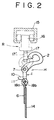
- FIG. 2 is a side view, partly cutaway, of the hanger device and the associate parts shown in FIG. 1, a curtain rod being shown in phantom lines.
- FIG. 3 is a side view, partly cutaway, of the hanger device of FIG. 1 but showing a hook portion locked to a hanger body.
- FIG. 4 is a front view of a hanger device according to a second embodiment of the present invention.
- FIG. 5 is also a front view of the hanger device of FIG. 4, but showing a hook portion locked to a hanger body.
- FIG. 6 is a fragmentary perspective view of a hanger device according to a third embodiment of the present invention.
- FIG. 7 is a fragmentary front view of the hanger device of FIG. 6.
- FIG. 8 is a fragmentary front view of the hanger device of FIG. 6 as well, but showing a hook portion locked to a hanger body.
- FIG. 9 is a fragmentary side view of the hanger device as shown in FIG. 8.
- FIG. 10 is a fragmentary side view of a hanger device according to a fourth embodiment of the present invention.
- FIG. 11 is a fragmentary side view of the hanger device of FIG. 10 but showing a hook portion inclined somewhat backward.
- FIG. 12 is a fragmentary side view of the hanger device of FIG. 10 but showing the hook portion locked to a hanger device.
- FIGS. 1 through 3 show a first embodiment of the present invention.
- a hanger device H according to the present invention is intended for hanging a curtain 14 to a curtain rod 15 via a curtain runner R reciprocally mounted on the curtain rod 15.
- the hanger device H broadly comprises a substantially rectangular hanger body 1 attached to the curtain 14 via an attachment tape 6 and a hook portion 2 pivotally mounted on the upper portion of the hanger body 1; the hanger body 1 and the hook portion 2 being separate but each being made of synthetic resin.
- the hanger body 1 comprises a thickened base 4 having a U-shaped cross-section and mounted on an upper marginal edge of the elongated marginal attachment tape 6, a pair of juxtaposed flanges 3, 3 extending from the top and disposed on the opposite ends of the thickened base 4, and a pair of coaxial sleeves 5,5 mounted on the tops of the respective flanges 3, 3, the sleeves 5, 5 extending longitudinally of the attachment tape 6.
- the thickened base 4 is mounted astraddle of the longitudinal marginal edge of the tape 6 with one leg 4a, 4b on either side of the tape 6.
- the hanger body 1 is molded, by injection molding process, integrally astraddle the edge of the attachment tape 6.
- the hanger body 1 may further include a plurality of (four illustrated in the drawings) linking fingers 18a, 18b extending downward from the lower edge of each leg 4a, 4b and arranged in a row and in registry with the corresponding linking fingers 18b, 18a of the other leg 4b, 4a, respectively.
- the linking fingers 18a, 18b of the respective legs 4a, 4b are integrally welded to each other through the tape 6 during the injection molding. This advantageously causes increased bond of the hanger body 1 to the attachment tape 6.
- the hook portion 2 has a pivotal shaft 7 provided on its bottom.
- the pivotal shaft 7 extend perpendicular to and in opposite directions from the hook portion 2.
- the pivotal shaft 7 is fitted into the coaxial sleeves 5 so that the hook portion 2 is pivotally mounted on the hook body 1.
- the hanger body 1 may have a pair of coaxial pins mounted on the tops of the flanges 3, 3 and the hook portions 2 has a pair of coaxial sleeves mounted on the opposite sides therefor for pivotal engagement with the coaxial pins of the hanger body 1.
- the hook portion 2 is bent backward to cause a distal end 9 thereof to define a gap 8 with a stem 2' of the hook portion 2.
- the hanger body 1 further includes a locking lug 10 provided on the middle of the thickened base 4 and interposed between the opposed flanges 3, 3.
- the locking lug 10 projects in such a direction to be able to lock the distal end 9 of the hook portion 1 when the hook portion 2 assumes a inclined position as shown in FIG. 3.
- the protuberant locking lug 10 has a chamfer 11 on its lower corner for facilitate locking engagement with the distal end 9 of the hook portion 2 when the hook portion 2 is angularly moved to an inclined position.
- the curtain runner R includes a runner body 16 reciprocally mounted on the curtain rod 15 and a ring portion 17 mounted on the bottom of the runner body 16 so as to be capable of swiveling thereon, the ring portion 17 has a through hole 17' for receiving the hook portion 2 therein.
- a plurality of the hanger devices H described above are attached at uniform intervals longitudinally to the attachment tape 6.
- the attachment tape 6 is secured to and along the upper edge of the curtain 14 by means of sewing.
- the curtain 14 is hang to the curtain runners 16 reciprocally mounted on the curtain rod 15 by fitting each hook portion 2 into the through hole 17' of the ring portion 17 of a corresponding curtain runner R.
- the hook portion 2 assumes an upright position, as indicated by phantom lines in FIG. 2.
- the curtain 14 is removed from the curtain runners R by bringing the hook portions 2 of the hanger device H out of engagement with the ring portion 17 of the curtain runners R and then the hook portion 2 is angularly moved into an inclined position in order to bring the distal end 9 thereof into locking engagement with the protuberant locking lug 10 as shown in FIG. 3. Since the hook portion 2 is locked to the hanger body 1 against unnecessary oscillation, the hook portion 2 is immune from being entangled with the fabric system of the curtain 14 during laundering.
- FIGS. 4 and 5 show a second embodiment of the present invention.
- a thickened web 3' is integrally provided on the thickened base 4.
- a pair of coaxial sleeves 5', 5' are formed on the thickened webs 3, and disposed perpendicularly to the attachment tap 6. Since the coaxial sleeves 5', 5' and hence the pivotal shaft 7 fitted therein extend perpendicularly to the attachment tape 6, the hook portion 2 oscillates along the length of the attachment tape 6.
- a locking lug 10 is provided on a relevant end of the web 3.
- the protuberant locking lug 10 has a chamfer 11 on its lower corner to facilitate locking engagement with the distal end 9 of the hook portion 2 when the hook portion 2 assume the inclined position, as shown in FIG. 5.
- FIGS. 6 through 9 show a third embodiment which is substantially identical with the first embodiment. Only one difference resides in the positions of a locking lug 10 and a chamfer 12 formed thereon. As better shown in FIG. 7, the projecting locking lug 10 is deflected toward one flange 3a and has a chamfer 12 formed on one lateral corner remote from said one flange 3a. As the hook portion 2 angularly moves counterclockwise as viewed in FIG. 9., the hook portion 2 is swerved rightward progressively by the chamfer 12 as shown in FIG. 8 and causes its distal end 9 to come into locking engagement with a relevant side surface of the protuberant locking lug 10, when it comes to assume the inclined position as shown in FIG. 9.
- FIGS. 10 through 12 shows a fourth embodiment of the present invention.
- a pivotal shaft 7 and holes 13 of sleeves 5 are not circular but oblong in cross-section.
- the length of the minor axis of the oblong hole 13 of the sleeves 5 is less than the length of the major axis of the oblong shaft 7.
- the hanger device according to the present invention will enjoy the following advantages.
- the hook portion Since the hook portion is locked to the hanger body against unnecessary oscillation when its assumes an inclined position, the hook portion of the hanger device is less likely to catch the fabric system of the curtain when the curtain is laundered.
- the hook portion of the hanger device is completely immune from being entangled with the fabric system of the curtain, thus causing no damage upon the curtain even if the curtain is subjected to severe stresses during the laundering.
Abstract
Description
- The present invention relates to a hanger device used for hanging a curtain to curtain runners reciprocally mounted on a curtain rod or curtain rail.
- A typical example of this hanger device of the type concerned is described in Japanese Utility Model Application No. 2-95740 filed on September 11, 1990. This conventional hanger device comprises a hanger body attached to a curtain and a hook portion pivotally mounted on the hanger body and adapted for catching engagement with a curtain runner reciprocally mounted on a curtain rod. This conventional hanger device suffers the following disadvantages. When the curtain is laundered by washing machines, the curtain is subjected to severe stresses exerted by violent water whirlpool. During the laundering, the hook portions of the hanger devices are apt to freely oscillate relative to the hanger bodies and hence the curtain as a whole. Consequently, the hook portions of the hanger devices are prone to be heavily entangled with the fabric system of the curtain. Once the hook portions are heavily entangled with the system of the curtain, it is time-consuming and tedious to untangle the hook portions from the curtain. Forcible release of the hook portions from the curtain could fatally damage the curtain as a whole.
- If the curtain is made of a netting or openwork fabric such as laces, things are much worse. Since the hook portions pierce through coarse networks of the curtain laces over several layers, it is close to impossible to untangle hook portions from the curtain without permanently breaking the curtain.
- With the foregoing difficulties in view, it is therefor an object of the present invention to provide a hanger device which is quite immune from getting entangled with and damaging a fabric piece of a curtain when the curtain is laundered.
- According to the present invention, there is provided a hanger device for hanging a curtain to a curtain rod via a curtain runner reciprocally mounted on the curtain rod, the hanger device comprising a hanger body attached to the curtain, a hook portion pivotally mounted on the hanger body and adapted for hooking engagement with a curtain runner and means for locking the hook portion to the hanger body when the hook portion is angularly moved to an inclined position.
- Many other advantages and features of the present invention will become manifest to those versed in the art upon making reference to the detail description and the accompanying sheets of drawings in which preferred structural embodiments incorporating the principles of the present invention are shown by way of illustrative example.
- FIG. 1 is a fragmentary perspective view showing a hanger device according to a first embodiment of the present invention attached to a curtain and hooked to a curtain runner shown in phantom lines.
- FIG. 2 is a side view, partly cutaway, of the hanger device and the associate parts shown in FIG. 1, a curtain rod being shown in phantom lines.
- FIG. 3 is a side view, partly cutaway, of the hanger device of FIG. 1 but showing a hook portion locked to a hanger body.
- FIG. 4 is a front view of a hanger device according to a second embodiment of the present invention.
- FIG. 5 is also a front view of the hanger device of FIG. 4, but showing a hook portion locked to a hanger body.
- FIG. 6 is a fragmentary perspective view of a hanger device according to a third embodiment of the present invention.
- FIG. 7 is a fragmentary front view of the hanger device of FIG. 6.
- FIG. 8 is a fragmentary front view of the hanger device of FIG. 6 as well, but showing a hook portion locked to a hanger body.
- FIG. 9 is a fragmentary side view of the hanger device as shown in FIG. 8.
- FIG. 10 is a fragmentary side view of a hanger device according to a fourth embodiment of the present invention.
- FIG. 11 is a fragmentary side view of the hanger device of FIG. 10 but showing a hook portion inclined somewhat backward.
- FIG. 12 is a fragmentary side view of the hanger device of FIG. 10 but showing the hook portion locked to a hanger device.
- FIGS. 1 through 3 show a first embodiment of the present invention. As better shown in FIG. 2, a hanger device H according to the present invention is intended for hanging a
curtain 14 to acurtain rod 15 via a curtain runner R reciprocally mounted on thecurtain rod 15. As better shown in FIG. 1, the hanger device H broadly comprises a substantially rectangular hanger body 1 attached to thecurtain 14 via anattachment tape 6 and ahook portion 2 pivotally mounted on the upper portion of the hanger body 1; the hanger body 1 and thehook portion 2 being separate but each being made of synthetic resin. - The hanger body 1 comprises a thickened
base 4 having a U-shaped cross-section and mounted on an upper marginal edge of the elongatedmarginal attachment tape 6, a pair of juxtaposedflanges base 4, and a pair ofcoaxial sleeves respective flanges sleeves attachment tape 6. The thickenedbase 4 is mounted astraddle of the longitudinal marginal edge of thetape 6 with oneleg 4a, 4b on either side of thetape 6. - The hanger body 1 is molded, by injection molding process, integrally astraddle the edge of the
attachment tape 6. - Preferably, the hanger body 1 may further include a plurality of (four illustrated in the drawings) linking
fingers leg 4a, 4b and arranged in a row and in registry with the corresponding linkingfingers other leg 4b, 4a, respectively. And, the linkingfingers respective legs 4a, 4b are integrally welded to each other through thetape 6 during the injection molding. This advantageously causes increased bond of the hanger body 1 to theattachment tape 6. - The
hook portion 2 has apivotal shaft 7 provided on its bottom. Thepivotal shaft 7 extend perpendicular to and in opposite directions from thehook portion 2. Thepivotal shaft 7 is fitted into thecoaxial sleeves 5 so that thehook portion 2 is pivotally mounted on the hook body 1. Alternatively, the hanger body 1 may have a pair of coaxial pins mounted on the tops of theflanges hook portions 2 has a pair of coaxial sleeves mounted on the opposite sides therefor for pivotal engagement with the coaxial pins of the hanger body 1. - As shown in FIG. 1, the
hook portion 2 is bent backward to cause adistal end 9 thereof to define agap 8 with a stem 2' of thehook portion 2. - As shown in FIG. 1, the hanger body 1 further includes a
locking lug 10 provided on the middle of the thickenedbase 4 and interposed between theopposed flanges locking lug 10 projects in such a direction to be able to lock thedistal end 9 of the hook portion 1 when thehook portion 2 assumes a inclined position as shown in FIG. 3. Theprotuberant locking lug 10 has a chamfer 11 on its lower corner for facilitate locking engagement with thedistal end 9 of thehook portion 2 when thehook portion 2 is angularly moved to an inclined position. - As shown in FIG. 2, the curtain runner R includes a
runner body 16 reciprocally mounted on thecurtain rod 15 and aring portion 17 mounted on the bottom of therunner body 16 so as to be capable of swiveling thereon, thering portion 17 has a through hole 17' for receiving thehook portion 2 therein. - A plurality of the hanger devices H described above are attached at uniform intervals longitudinally to the
attachment tape 6. As better shown in FIG. 1, theattachment tape 6 is secured to and along the upper edge of thecurtain 14 by means of sewing. Subsequently, as better shown in FIG. 2, thecurtain 14 is hang to thecurtain runners 16 reciprocally mounted on thecurtain rod 15 by fitting eachhook portion 2 into the through hole 17' of thering portion 17 of a corresponding curtain runner R. In this instance, thehook portion 2 assumes an upright position, as indicated by phantom lines in FIG. 2. - For laundering the
curtain 14, thecurtain 14 is removed from the curtain runners R by bringing thehook portions 2 of the hanger device H out of engagement with thering portion 17 of the curtain runners R and then thehook portion 2 is angularly moved into an inclined position in order to bring thedistal end 9 thereof into locking engagement with theprotuberant locking lug 10 as shown in FIG. 3. Since thehook portion 2 is locked to the hanger body 1 against unnecessary oscillation, thehook portion 2 is immune from being entangled with the fabric system of thecurtain 14 during laundering. - FIGS. 4 and 5 show a second embodiment of the present invention. Instead of the pairs of flanges, a thickened web 3' is integrally provided on the thickened
base 4. A pair of coaxial sleeves 5', 5' are formed on the thickenedwebs 3, and disposed perpendicularly to theattachment tap 6. Since the coaxial sleeves 5', 5' and hence thepivotal shaft 7 fitted therein extend perpendicularly to theattachment tape 6, thehook portion 2 oscillates along the length of theattachment tape 6. For locking engagement with thehook portion 2, alocking lug 10 is provided on a relevant end of theweb 3. Similarly to that of the first embodiment, theprotuberant locking lug 10 has a chamfer 11 on its lower corner to facilitate locking engagement with thedistal end 9 of thehook portion 2 when thehook portion 2 assume the inclined position, as shown in FIG. 5. - FIGS. 6 through 9 show a third embodiment which is substantially identical with the first embodiment. Only one difference resides in the positions of a
locking lug 10 and achamfer 12 formed thereon. As better shown in FIG. 7, the projectinglocking lug 10 is deflected toward oneflange 3a and has achamfer 12 formed on one lateral corner remote from said oneflange 3a. As thehook portion 2 angularly moves counterclockwise as viewed in FIG. 9., thehook portion 2 is swerved rightward progressively by thechamfer 12 as shown in FIG. 8 and causes itsdistal end 9 to come into locking engagement with a relevant side surface of theprotuberant locking lug 10, when it comes to assume the inclined position as shown in FIG. 9. - FIGS. 10 through 12 shows a fourth embodiment of the present invention. In this embodiment, there is no protuberant locking lug. Unlike those in the preceding embodiments, a
pivotal shaft 7 andholes 13 ofsleeves 5 are not circular but oblong in cross-section. It is to be noted that the length of the minor axis of theoblong hole 13 of thesleeves 5 is less than the length of the major axis of theoblong shaft 7. With such a dimensional arrangement, as thehook portion 2 moves angularly counterclockwise as viewed in FIG. 10, thehook portion 2 causes its oblongpivotal shaft 7 come into locking engagement with theoblong holes 13 of thesleeves 5, so that thehook portion 2 comes into locking engagement with the hanger body 1 when it assumes an inclined position, as shown in FIG. 12. - It is to be noted here that, in any of the embodiments set forth hereinabove, when the
hook portion 2 comes into locking engagement with the hanger body 1, thedistal end 9 of thehook portion 2 is closed by either thelocking lug 10 or the hanger body 1 itself (FIG. 12) to ensure that thehook portion 2 is completely immune from catching the fabric system of thecurtain 14. - With the construction set forth above, the hanger device according to the present invention will enjoy the following advantages.
- Since the hook portion is locked to the hanger body against unnecessary oscillation when its assumes an inclined position, the hook portion of the hanger device is less likely to catch the fabric system of the curtain when the curtain is laundered.
- Besides that, if the hook portion is locked to the hanger body with the distal end of the hook portion closed, the hook portion of the hanger device is completely immune from being entangled with the fabric system of the curtain, thus causing no damage upon the curtain even if the curtain is subjected to severe stresses during the laundering.
- Obviously, various modifications and variations of the present invention are possible in the light of the above teaching. It is therefore to be understood that within the scope of the appended claims the invention may be practiced otherwise than as specifically described.
Claims (4)
- A hanger device (H) for hanging a curtain (14) to a curtain rod (15) via a curtain runner (R) reciprocally mounted on the curtain rod (15), the hanger device (H) comprising a hanger body (1) attached to the curtain (14) and a hook portion (2) pivotally mounted on the hanger body (1) and adapted for hooking engagement with a curtain runner (R), characterized in that the hanger device (H) further includes means (10, 11; 12; 7, 13) for locking the hook portion (2) to the hanger body (1) when the hook portion (2) is angularly moved to an inclined position.
- A hanger device (H) according to claim 1, a distal end (9) of the hook portion (2) being closed by the hanger body (1) when the hook portion (2) assumes the inclined position.
- A hanger device (H) according to claim 1, the locking means (10, 11; 12; 7, 13) comprising a protuberant lug (10) mounted on the hanger body (1) and having a chamfer (11, 12) on a distal end thereof, the distal end (9) of the hook portion (2) coming into locking engagement with the protuberant lug (10) when the hook portion (2) assumes the inclined position.
- A hanger device (H) according to claim 1, the locking means (10, 11; 12; 7, 13) comprising a pair of coaxial sleeves (5, 5) formed on an upper part of the hanger body (1) and having oblong through holes (13, 13) and a pivotal shaft (7) mounted on a lower part of the hook portion (2) and extending in opposite directions therefrom, the pivotal shaft (7) being pivotally fitted into the oblong holes (13, 13) of the coaxial sleeves (5,5), the length of the minor axis of the oblong holes (13, 13) of the sleeves (5, 5) being less than the length of the major axis of the oblong shaft (7).
Applications Claiming Priority (2)
| Application Number | Priority Date | Filing Date | Title |
|---|---|---|---|
| JP1991087081U JP2526705Y2 (en) | 1991-09-27 | 1991-09-27 | Curtain hanger |
| JP87081/91U | 1991-09-27 |
Publications (2)
| Publication Number | Publication Date |
|---|---|
| EP0534642A1 true EP0534642A1 (en) | 1993-03-31 |
| EP0534642B1 EP0534642B1 (en) | 1996-05-01 |
Family
ID=13905001
Family Applications (1)
| Application Number | Title | Priority Date | Filing Date |
|---|---|---|---|
| EP92308243A Expired - Lifetime EP0534642B1 (en) | 1991-09-27 | 1992-09-10 | Hanger device |
Country Status (4)
| Country | Link |
|---|---|
| US (1) | US5291632A (en) |
| EP (1) | EP0534642B1 (en) |
| JP (1) | JP2526705Y2 (en) |
| DE (1) | DE69210341T2 (en) |
Cited By (3)
| Publication number | Priority date | Publication date | Assignee | Title |
|---|---|---|---|---|
| DE19904731A1 (en) * | 1999-02-05 | 2000-08-10 | Johann Maurer | Hanging system for curtains consists of carrier (2) with roller which fits into curtain rail and has peg below it and releasable curtain hook with upper stirrup-shaped portion which fits over head on carrier |
| FR2800794A1 (en) | 1999-11-05 | 2001-05-11 | Rehau Sa | Housing for roller blind has housing with profile forming groove to receive suspension hooks of blind |
| WO2019032056A1 (en) * | 2017-08-10 | 2019-02-14 | Leowkijsiri Phalatt | Multi-material foldable product |
Families Citing this family (22)
| Publication number | Priority date | Publication date | Assignee | Title |
|---|---|---|---|---|
| CA2120810C (en) * | 1993-04-15 | 1998-01-06 | Ykk Corporation | Curtain attachment connector assembly and curtain attachment connector |
| US6038749A (en) * | 1998-03-12 | 2000-03-21 | Eberhardt; Stephanie A. | Hook and loop combined shower curtain and liner construction |
| TW362690U (en) * | 1998-05-12 | 1999-06-21 | Zhen-Xiang Li | Structure for hanging pulley of movable partitioned door |
| US6098246A (en) * | 1998-12-08 | 2000-08-08 | Moir; Alan R. | Adapter for conversion of vertical blinds to curtains |
| US6334477B1 (en) | 2000-04-20 | 2002-01-01 | Alan R. Moir | Adapter for hanging blinds and curtains |
| SE526396C2 (en) * | 2003-11-07 | 2005-09-06 | Stefan Schoerling | Curtain Hanging Device |
| CN102014706B (en) * | 2008-04-25 | 2013-07-24 | 赛林特格宁斯国际股份公司 | Carriage for a curtain device |
| US8869869B2 (en) | 2008-05-22 | 2014-10-28 | Icp Medical, Llc | Systems and methods for deployment of curtains |
| US9125509B2 (en) * | 2008-05-22 | 2015-09-08 | Icp Medical, Llc | Methods and systems for deployment of curtains |
| US8479800B2 (en) | 2008-05-22 | 2013-07-09 | Icp Medical, Llc | Systems and methods for deployment of curtains |
| US9149144B2 (en) * | 2008-05-22 | 2015-10-06 | Icp Medical, Llc | Systems and methods for deployment of curtains |
| US8899301B2 (en) * | 2008-05-22 | 2014-12-02 | Icp Medical, Llc | Methods and systems for deployment of curtains |
| US20100125987A1 (en) * | 2008-11-27 | 2010-05-27 | Ted Barkun | Curtain carrier for draping a curtain from a curtain rod |
| TWM475239U (en) * | 2013-10-28 | 2014-04-01 | Arlinea Ind Co | Hanging type slide base |
| EP3171738A2 (en) | 2014-07-24 | 2017-05-31 | Paskal Zippers Ltd | Mounting system for mounting a sheet element with respect to a rail element |
| CN206964506U (en) * | 2017-01-04 | 2018-02-06 | 许敏 | A kind of Simple curtain class hook |
| WO2019162947A1 (en) | 2018-02-26 | 2019-08-29 | Slide2Seal Ltd. | Mounting strip |
| US20220015567A1 (en) * | 2020-07-20 | 2022-01-20 | Bannack Medical LLC | Disposable curtain system, attachment therefor and method |
| USD982422S1 (en) | 2020-10-19 | 2023-04-04 | Bannack Medical LLC | Hook attachment |
| USD1012551S1 (en) | 2021-04-14 | 2024-01-30 | Bannack Medical LLC | Curtain quick release |
| USD1011869S1 (en) | 2021-04-14 | 2024-01-23 | Bannack Medical LLC | Curtain hanging assembly |
| US11864681B2 (en) | 2021-03-08 | 2024-01-09 | Bannack Medical LLC | Disposable curtain system and a lockable quick-release system therefor and method |
Citations (4)
| Publication number | Priority date | Publication date | Assignee | Title |
|---|---|---|---|---|
| DE2306670A1 (en) * | 1973-02-10 | 1974-09-05 | Luedenscheid Spritzguss Werk | CURTAIN HANGERS, ESPECIALLY. WITH ROLES |
| FR2290872A1 (en) * | 1974-11-12 | 1976-06-11 | Gardisette Holding | SUSPENSION DEVICE FOR BLINDS AND CURTAINS |
| DE2613740A1 (en) * | 1976-03-31 | 1977-10-06 | Waldemar Dr Buenger | Pleat forming curtain heading with draw cord - has hooks with supports to take up excess draw cord on coil throughout curtain heading |
| FR2360740A1 (en) * | 1976-08-04 | 1978-03-03 | Bratschi Silent Gliss | BLADE CURTAIN |
Family Cites Families (3)
| Publication number | Priority date | Publication date | Assignee | Title |
|---|---|---|---|---|
| AT185530B (en) * | 1955-01-19 | 1956-05-11 | Adalbert Kanngiesser | Roller hanger for curtains |
| DE1147430B (en) * | 1960-04-02 | 1963-04-18 | Fidel Simmendinger K G | Snap hook |
| US3596306A (en) * | 1968-08-27 | 1971-08-03 | Andre Y Wachenheimer | Cafe and like curtain hangers |
-
1991
- 1991-09-27 JP JP1991087081U patent/JP2526705Y2/en not_active Expired - Fee Related
-
1992
- 1992-09-10 EP EP92308243A patent/EP0534642B1/en not_active Expired - Lifetime
- 1992-09-10 DE DE69210341T patent/DE69210341T2/en not_active Expired - Fee Related
- 1992-09-28 US US07/951,847 patent/US5291632A/en not_active Expired - Lifetime
Patent Citations (4)
| Publication number | Priority date | Publication date | Assignee | Title |
|---|---|---|---|---|
| DE2306670A1 (en) * | 1973-02-10 | 1974-09-05 | Luedenscheid Spritzguss Werk | CURTAIN HANGERS, ESPECIALLY. WITH ROLES |
| FR2290872A1 (en) * | 1974-11-12 | 1976-06-11 | Gardisette Holding | SUSPENSION DEVICE FOR BLINDS AND CURTAINS |
| DE2613740A1 (en) * | 1976-03-31 | 1977-10-06 | Waldemar Dr Buenger | Pleat forming curtain heading with draw cord - has hooks with supports to take up excess draw cord on coil throughout curtain heading |
| FR2360740A1 (en) * | 1976-08-04 | 1978-03-03 | Bratschi Silent Gliss | BLADE CURTAIN |
Cited By (4)
| Publication number | Priority date | Publication date | Assignee | Title |
|---|---|---|---|---|
| DE19904731A1 (en) * | 1999-02-05 | 2000-08-10 | Johann Maurer | Hanging system for curtains consists of carrier (2) with roller which fits into curtain rail and has peg below it and releasable curtain hook with upper stirrup-shaped portion which fits over head on carrier |
| DE19904731C2 (en) * | 1999-02-05 | 2001-03-08 | Johann Maurer | Curtain hanging system |
| FR2800794A1 (en) | 1999-11-05 | 2001-05-11 | Rehau Sa | Housing for roller blind has housing with profile forming groove to receive suspension hooks of blind |
| WO2019032056A1 (en) * | 2017-08-10 | 2019-02-14 | Leowkijsiri Phalatt | Multi-material foldable product |
Also Published As
| Publication number | Publication date |
|---|---|
| US5291632A (en) | 1994-03-08 |
| JP2526705Y2 (en) | 1997-02-19 |
| DE69210341T2 (en) | 1996-11-28 |
| JPH0528278U (en) | 1993-04-16 |
| DE69210341D1 (en) | 1996-06-05 |
| EP0534642B1 (en) | 1996-05-01 |
Similar Documents
| Publication | Publication Date | Title |
|---|---|---|
| EP0534642B1 (en) | Hanger device | |
| US4046293A (en) | Detachable bar for garment hanger | |
| KR0184597B1 (en) | Curtain attachment connector | |
| US5836486A (en) | Hanger bar | |
| EP0101064B1 (en) | Strap guide for strap adjustment assembly | |
| US4889265A (en) | Folding pant hanger | |
| US5359754A (en) | Top end stop for concealed slide fastener | |
| US4321733A (en) | Slide fastener stringer | |
| US4919281A (en) | Fabric bolt hanger | |
| US7703183B2 (en) | Coil zipper structure | |
| JPH06122A (en) | Curtain rail runner, curtain holder and curtain | |
| JPH0132938Y2 (en) | ||
| US4529110A (en) | Attachment to improve wire or other coathangers | |
| JP3071458U (en) | Hanging tape for curtain | |
| JP3160613B2 (en) | Tape with snap button | |
| JP3950525B2 (en) | Solid hanger | |
| JP3079062U (en) | Clothes hanger | |
| JPH0243207Y2 (en) | ||
| US4020529A (en) | Unfastening button, particularly for upholstery | |
| JPS588237Y2 (en) | laundry pole | |
| JPH0746213Y2 (en) | Hanger | |
| JPH0636796Y2 (en) | Curtain hangings | |
| JP3030058U (en) | Laundry net | |
| JP3071274U (en) | Squid fishing hook | |
| JPH0115345Y2 (en) |
Legal Events
| Date | Code | Title | Description |
|---|---|---|---|
| PUAI | Public reference made under article 153(3) epc to a published international application that has entered the european phase |
Free format text: ORIGINAL CODE: 0009012 |
|
| AK | Designated contracting states |
Kind code of ref document: A1 Designated state(s): DE FR GB IT |
|
| 17P | Request for examination filed |
Effective date: 19930630 |
|
| RAP1 | Party data changed (applicant data changed or rights of an application transferred) |
Owner name: YKK CORPORATION |
|
| 17Q | First examination report despatched |
Effective date: 19950403 |
|
| GRAH | Despatch of communication of intention to grant a patent |
Free format text: ORIGINAL CODE: EPIDOS IGRA |
|
| GRAA | (expected) grant |
Free format text: ORIGINAL CODE: 0009210 |
|
| AK | Designated contracting states |
Kind code of ref document: B1 Designated state(s): DE FR GB IT |
|
| ITF | It: translation for a ep patent filed |
Owner name: JACOBACCI & PERANI S.P.A. |
|
| ET | Fr: translation filed | ||
| REF | Corresponds to: |
Ref document number: 69210341 Country of ref document: DE Date of ref document: 19960605 |
|
| PLBE | No opposition filed within time limit |
Free format text: ORIGINAL CODE: 0009261 |
|
| STAA | Information on the status of an ep patent application or granted ep patent |
Free format text: STATUS: NO OPPOSITION FILED WITHIN TIME LIMIT |
|
| 26N | No opposition filed | ||
| REG | Reference to a national code |
Ref country code: GB Ref legal event code: IF02 |
|
| PGFP | Annual fee paid to national office [announced via postgrant information from national office to epo] |
Ref country code: FR Payment date: 20050823 Year of fee payment: 14 |
|
| PGFP | Annual fee paid to national office [announced via postgrant information from national office to epo] |
Ref country code: GB Payment date: 20050907 Year of fee payment: 14 |
|
| PGFP | Annual fee paid to national office [announced via postgrant information from national office to epo] |
Ref country code: DE Payment date: 20050909 Year of fee payment: 14 |
|
| PGFP | Annual fee paid to national office [announced via postgrant information from national office to epo] |
Ref country code: IT Payment date: 20060930 Year of fee payment: 15 |
|
| PG25 | Lapsed in a contracting state [announced via postgrant information from national office to epo] |
Ref country code: DE Free format text: LAPSE BECAUSE OF NON-PAYMENT OF DUE FEES Effective date: 20070403 |
|
| GBPC | Gb: european patent ceased through non-payment of renewal fee |
Effective date: 20060910 |
|
| REG | Reference to a national code |
Ref country code: FR Ref legal event code: ST Effective date: 20070531 |
|
| PG25 | Lapsed in a contracting state [announced via postgrant information from national office to epo] |
Ref country code: GB Free format text: LAPSE BECAUSE OF NON-PAYMENT OF DUE FEES Effective date: 20060910 |
|
| PG25 | Lapsed in a contracting state [announced via postgrant information from national office to epo] |
Ref country code: FR Free format text: LAPSE BECAUSE OF NON-PAYMENT OF DUE FEES Effective date: 20061002 |
|
| PG25 | Lapsed in a contracting state [announced via postgrant information from national office to epo] |
Ref country code: IT Free format text: LAPSE BECAUSE OF NON-PAYMENT OF DUE FEES Effective date: 20070910 |