EP0534554A2 - A burner low in the generation of nitrogen oxides and a small combustion apparatus - Google Patents
A burner low in the generation of nitrogen oxides and a small combustion apparatus Download PDFInfo
- Publication number
- EP0534554A2 EP0534554A2 EP92202918A EP92202918A EP0534554A2 EP 0534554 A2 EP0534554 A2 EP 0534554A2 EP 92202918 A EP92202918 A EP 92202918A EP 92202918 A EP92202918 A EP 92202918A EP 0534554 A2 EP0534554 A2 EP 0534554A2
- Authority
- EP
- European Patent Office
- Prior art keywords
- burner
- units
- burner units
- fuel
- flame
- Prior art date
- Legal status (The legal status is an assumption and is not a legal conclusion. Google has not performed a legal analysis and makes no representation as to the accuracy of the status listed.)
- Granted
Links
- MWUXSHHQAYIFBG-UHFFFAOYSA-N nitrogen oxide Inorganic materials O=[N] MWUXSHHQAYIFBG-UHFFFAOYSA-N 0.000 title claims abstract description 76
- 238000002485 combustion reaction Methods 0.000 title claims abstract description 65
- 239000000446 fuel Substances 0.000 claims abstract description 71
- 239000000203 mixture Substances 0.000 claims abstract description 63
- 239000002737 fuel gas Substances 0.000 claims abstract description 43
- 239000007789 gas Substances 0.000 claims description 42
- 238000000638 solvent extraction Methods 0.000 claims description 4
- 238000002347 injection Methods 0.000 claims 1
- 239000007924 injection Substances 0.000 claims 1
- 230000003247 decreasing effect Effects 0.000 abstract description 4
- 230000002708 enhancing effect Effects 0.000 abstract 1
- 238000010586 diagram Methods 0.000 description 8
- 230000014759 maintenance of location Effects 0.000 description 7
- 230000000694 effects Effects 0.000 description 6
- 238000005259 measurement Methods 0.000 description 5
- 238000001816 cooling Methods 0.000 description 4
- 239000000567 combustion gas Substances 0.000 description 3
- 238000010276 construction Methods 0.000 description 3
- 230000007423 decrease Effects 0.000 description 3
- 238000001514 detection method Methods 0.000 description 2
- 238000005192 partition Methods 0.000 description 2
- 230000002829 reductive effect Effects 0.000 description 2
- 238000003916 acid precipitation Methods 0.000 description 1
- 239000000919 ceramic Substances 0.000 description 1
- 229910010293 ceramic material Inorganic materials 0.000 description 1
- 239000012530 fluid Substances 0.000 description 1
- 239000002184 metal Substances 0.000 description 1
- 230000036961 partial effect Effects 0.000 description 1
- 230000001105 regulatory effect Effects 0.000 description 1
- 230000002441 reversible effect Effects 0.000 description 1
- 230000003068 static effect Effects 0.000 description 1
- 231100000331 toxic Toxicity 0.000 description 1
- 230000002588 toxic effect Effects 0.000 description 1
- 238000011144 upstream manufacturing Methods 0.000 description 1
Images


Classifications
-
- F—MECHANICAL ENGINEERING; LIGHTING; HEATING; WEAPONS; BLASTING
- F23—COMBUSTION APPARATUS; COMBUSTION PROCESSES
- F23D—BURNERS
- F23D14/00—Burners for combustion of a gas, e.g. of a gas stored under pressure as a liquid
- F23D14/26—Burners for combustion of a gas, e.g. of a gas stored under pressure as a liquid with provision for a retention flame
-
- F—MECHANICAL ENGINEERING; LIGHTING; HEATING; WEAPONS; BLASTING
- F23—COMBUSTION APPARATUS; COMBUSTION PROCESSES
- F23D—BURNERS
- F23D14/00—Burners for combustion of a gas, e.g. of a gas stored under pressure as a liquid
- F23D14/02—Premix gas burners, i.e. in which gaseous fuel is mixed with combustion air upstream of the combustion zone
- F23D14/04—Premix gas burners, i.e. in which gaseous fuel is mixed with combustion air upstream of the combustion zone induction type, e.g. Bunsen burner
- F23D14/045—Premix gas burners, i.e. in which gaseous fuel is mixed with combustion air upstream of the combustion zone induction type, e.g. Bunsen burner with a plurality of burner bars assembled together, e.g. in a grid-like arrangement
-
- F—MECHANICAL ENGINEERING; LIGHTING; HEATING; WEAPONS; BLASTING
- F23—COMBUSTION APPARATUS; COMBUSTION PROCESSES
- F23D—BURNERS
- F23D14/00—Burners for combustion of a gas, e.g. of a gas stored under pressure as a liquid
- F23D14/02—Premix gas burners, i.e. in which gaseous fuel is mixed with combustion air upstream of the combustion zone
- F23D14/04—Premix gas burners, i.e. in which gaseous fuel is mixed with combustion air upstream of the combustion zone induction type, e.g. Bunsen burner
- F23D14/10—Premix gas burners, i.e. in which gaseous fuel is mixed with combustion air upstream of the combustion zone induction type, e.g. Bunsen burner with elongated tubular burner head
- F23D14/105—Premix gas burners, i.e. in which gaseous fuel is mixed with combustion air upstream of the combustion zone induction type, e.g. Bunsen burner with elongated tubular burner head with injector axis parallel to the burner head axis
-
- F—MECHANICAL ENGINEERING; LIGHTING; HEATING; WEAPONS; BLASTING
- F23—COMBUSTION APPARATUS; COMBUSTION PROCESSES
- F23D—BURNERS
- F23D14/00—Burners for combustion of a gas, e.g. of a gas stored under pressure as a liquid
- F23D14/46—Details, e.g. noise reduction means
- F23D14/48—Nozzles
- F23D14/58—Nozzles characterised by the shape or arrangement of the outlet or outlets from the nozzle, e.g. of annular configuration
-
- F—MECHANICAL ENGINEERING; LIGHTING; HEATING; WEAPONS; BLASTING
- F23—COMBUSTION APPARATUS; COMBUSTION PROCESSES
- F23D—BURNERS
- F23D2210/00—Noise abatement
Definitions
- the present invention relates to a burner which is low in the generation of nitrogen oxides, used in a small combustion apparatus for domestic or commercial use.
- the nitrogen oxides (NO x ) in the exhaust gases from burners of various combustion apparatuses are themselves toxic and are believed to cause acid rain and photochemical smog. So, for burners used in combustion apparatuses, various measures for decreasing the generation of NO x have been developed and utilized.
- the large static pressure given by the combustion fan provides advantages such that the combustion gas and air can be easily controlled in flow.
- the burner is high in the degree of freedom of layout, and noise can be controlled easily. So, noise control is not difficult, and since the combustion chamber can be large, slow combustion as a means for decreasing NO x allows one to easily achieve perfect combustion.
- a small combustion apparatus especially a small combustion apparatus for burning a large quantity, these advantages are not available and it is difficult to take measures for decreasing NO x , as compared to large combustion apparatuses.
- the objects of the present invention are to achieve a higher burner unit mounting density allowing a larger quantity of combustion and to achieve stable combustion using a lean fuel mixture to decrease nitrogen oxides and reduce noise.
- Figure 1 is a perspective view showing the first burner unit comprising the burner of the present invention as an example.
- Figure 2 is a section taken along the X-X line of Figure 1.
- Figure 3 is a section taken along the Y-Y line of Figure 1.
- Figure 4 is a perspective view showing the second burner unit comprising the burner of the present invention as an example.
- Figure 5 is a plan view showing the construction of the burner of an embodiment of the present invention with some omission.
- Figure 6 is a partially cutaway front view showing the construction of the burner of the arrangement of the present invention.
- Figures 7A and Figure 7B are an enlarged front view showing a portion of Figure 6.
- Figure 8 is a side view showing the construction embodying the present invention.
- Figure 9 is a front view showing the nozzle holders constituting the burner arrangement of the present invention, viewed from the side reverse to the nozzles.
- Figure 10 is a side view showing the nozzle holders shown in Figure 9.
- Figure 11 is a diagram showing the quantities of NO x generated by the burner embodying the present invention, in comparison with the conventional Bunsen burner.
- Figure 12 is an illustration showing the lift limit of flames of the first burner units in the burner of the present invention as an example, in comparison with others.
- Figure 13 is a diagram showing measured noise levels during combustion by the burners in conformity with the present invention.
- Figure 14 is a perspective view showing a portion of another embodiment.
- Figure 15 is a perspective view showing a portion as a further embodiment.
- Figure 16 is a perspective view showing a portion as a still further embodiment.
- the burner low in the generation of nitrogen oxides of the present invention comprises respectively plural first and second burner units, said units being arranged alternately adjacently to one another; each of the burner units, being composed of a flame port portion at the top of the burner body which is vertical and flat, and an inlet for fuel gas and air at the bottom of the burner body, and a mixing channel extending from the inlet to the flame port portion; the inlets of the first burner units; being located below the inlets of the second burner units; and fuel gas spouts, being provided to correspond to the respective inlets of the first and second burner units; wherein a lean fuel mixture is supplied to the first burner units, with the quantity of fuel gas kept larger than that supplied to the second burner units, and a rich fuel mixture is supplied to the second burner units.
- each of the burner bodies consists of a thin top section provided with a flame port portion at the top end and a thick bottom section provided with an inlet and a mixer tube, and each of the bottom sections of the second burner units is positioned between the top sections of the first burner units.
- a burner low in the generation of nitrogen oxides comprising respectively plural first and second burner units, said units being arranged alternately adjacently to one another; each of the burner units being composed of a flame port portion at the top of the burner body, and an inlet for combustion gas and air at the bottom of the burner body, and a mixing channel extending from the inlet to the flame port portion; fuel gas spouts, said spouts being provided to correspond to the respective inlets of the first and second burner units; and gas flow guide channels length not less than 5 times the equivalent diameter of the flame ports, which are provided at the flame port portions of the first burner units; wherein a lean fuel mixture is supplied to the first burner units, with the quantity of fuel gas kept larger than that supplied to the second burner units, and a rich fuel mixture is supplied to the second burner units.
- gas flow guide channels having a length not less than 5 times the equivalent diameter of the flame port, can be provided also at the flame port portions of the second burner units.
- the gas flow guide channels can be formed by partitioning the channels to the flame ports by gas flow guide plates or by thick plates with flame ports perforated through them.
- the inlets for fuel gas and air of the first burner units are located below the inlets of the second burner units, to present the inlets at two different stages, and the first and second burner units are arranged alternately and adjacently to one another. So, the burner units are arranged at a high density. In this case, if the top section with the flame port portion of each of the first burner units is made thinner than the bottom section with the inlet and the mixer tube of the first burner unit, and each of the lower sections of the second burner units is located between the adjacent top sections of the first burner units, then the burner units can be arranged at a high density.
- the distance from the inlet to the flame port portion in each of the first burner units is longer than that in each of the second burner units, and so the mixing of fuel gas and air is achieved well in the first burner units. Therefore, in the first burner units, a large quantity of air-fuel mixture with lean fuel uniformly mixed, can be supplied to the flame port portions.
- the lean fuel mixture is spouted for burning from the flame port portions of the first burner units, and the rich fuel mixture is spouted for burning from the flame port portions of the second burner units.
- the temperature of the flames is kept low by the cooling action of the air rich mixture to generate less NO x . Furthermore, since the quantity of the fuel gas presented for combustion as the lean fuel mixture is larger than the quantity of the fuel gas presented as the rich fuel mixture, the quantity of the NO x generated is small compared to the quantity of combustion by the entire burner.
- the combustion noise greatly depends on the spouting condition of the air-fuel mixture from the flame ports of a burner, and if the spouting condition is turbulent, the combustion noise is large.
- gas flow guide channels having lengths not less than 5 times the equivalent diameter of the flame ports are provided to spout the air-fuel mixture in a sufficiently regular flow, combustion noise can be effectively reduced.
- the quantity of the air-fuel mixture spouted from the first burner units is larger than that from the second burner units, air rich mixture is burned.
- the noise reduction effect by the gas flow guide channels is achieved more than the first burner units.
- Figs. 1 and 4 are perspective views showing the first and second burner units 1a and 1b of the present invention respectively, as examples of embodiment.
- a flame port portion 3a or 3b is provided at the top of a vertical and flat burner body 2a or 2b, and an inlet 4a or 4b for fuel gas and air is provided at the bottom of the burner body, while a mixer tube 5a or 5b extends from the inlet 4a or 4b to the flame port portion 3a or 3b.
- the height of the burner body 2a of the first burner unit 1a is larger than that of the burner body 2b of the second burner unit 1b, and so the distance from the inlet 4a to the flame port portion 3a is longer than that of the second burner unit 1b.
- Each of the burner bodies 2a and 2b of the first and second burner units 1a and 1b consists of a thin top section u with the flame port portion 3a and 3b at the top end and a thick bottom section d with the inlet 4a or 4b and the mixer tube 5a or 5b.
- the flame port portion 3a or 3b has plural short-slit openings arranged in one row formed by narrowing a long-slit opening at the top end of the top section u at predetermined intervals.
- the flame port portion 3a or 3b can have many slits provided crosswise, or any other proper structure can be adopted.
- the flame port portion 3a has two strips 6a provided at a predetermined gap as gas flow guide plates, and the strips 6a are held in the top section u, to form nine short-slit portions 7a, each with three slits, at predetermined spacings in the longitudinal direction.
- the flame port portion 3b has one strip 6b as a gas flow plate in the top portion u of the burner body 2b, and the strip 6b is held in the top section u, to form nine short-slit portions 7b, each with two slits, at predetermined spacings in the longitudinal direction.
- the vertical length of the strips 6a and 6b are not less than 5 times the equivalent diameter of the short-slit portions 7a and 7b.
- the equivalent diameter is defined, as is known, by 4S/L where S is the sectional area of a pipeline through which a fluid flows, and L is the perimeter.
- S is the sectional area of a pipeline through which a fluid flows
- L is the perimeter.
- Each of the inlets 4a and 4b is formed as an opening of the bottom section d. Inside the opening, a throat 5'a or 5'b is formed. From the throat 5'a or 5'b, the mixer tube 5a or 5b extends to the other end of the bottom section d and returns from there to the bottom end of the top section u.
- the inlet 4a and the mixer tube 5a of the first burner unit 1a are larger in diameter than those of the second burner 1b, to allow introduction of more fuel gas and air.
- each of the first and second burner units 1a and 1b has a throttle portion 8a or 8b across the top section u, and the first burner unit 1a is provided with narrowing portions 9 as gas flow guide portions at predetermined spacings upstream of the throttle portion 8a.
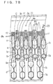
- a flame retention plate 10 is provided outside the top section u of the second burner unit 1b, as shown in Fig. 7A and Fig. 7B, and to correspond to the flame retention plate 10, the top section u is provided with an air-fuel mixture ejection hole 20 for flame retention.
- Figs. 5 to 8 show the entire structure of the burner composed of the first and second burner units 1a and 1b.
- Fig. 5 is a plan view showing the whole, but with some repeating parts omitted.
- Fig. 6 is a front view showing the whole where the air chamber 11 and first and second nozzle holders 12a and 12b described later are partially cut away.
- Fig. 7 is an expanded front view showing an essential portion of Fig. 6 and combustion state.
- Fig. 8 is its side view.
- first and second burner units 1a and 1b are arranged alternately with their flame port portions 3a and 3b held with their tops at the same level or at some different levels, and supported in a housing 13.
- the tops of the flame port portions 3a of the first burner units 1a are somewhat lower than those of the flame port portions 3b of the second burner units 1b, and are almost the same as the tops of the flame retention plates 10.
- Figs. 5 and 6 at both ends of the burner unit 1a, one each of the second burner units 1b is located.
- the height of the burner bodies 2a of the first burner units 1a are larger than the height of the burner bodies 2b of the second burner units 1b. So, as shown in Figs. 6 to 8, the inlets 4a of the first burner units 1a are arranged in one horizontal row at a position below the inlets 4b of the second burner units 1b. Furthermore, the inlets 4b of the second burner units 1b are arranged in one horizontal row between the top section u of the burner bodies 2a of the first burner units 1a.
- the adjacent top sections u of the first and second burner units 1a and 1b can be arranged at narrow spacings, and for this reason these first and second burner units 1a and 1b can be mounted at a high density.
- the housing 13 has lower and upper nozzle holders 12a and 12b corresponding to the lower and upper rows of the inlets 4a and 4b of the first and second burner units 1a and 1b, that is, the lower first nozzle holder 12a corresponding to the first burner units 1a and the upper second nozzle holder 12b corresponding to the second burner units 1b are provided. These nozzle holders 12a and 12b are installed in an air chamber 11 opened in front, and fan 14 supplies air into the air chamber 11.
- the first, and second nozzle holders 12a and 12b respectively have fuel gas ejection nozzles 15a and 15b corresponding to the inlets 4a and 4b.
- the diameters and locations of the nozzles 15a and 15b and the diameters of the inlets 4a and 4b are set to satisfy the following conditions.
- the components corresponding to the first burner units 1a are set to satisfy the condition that a lean fuel mixture larger in quantity of fuel gas than that for the second burner units 1b may be supplied to the flame port portions 3a, and the above components corresponding to the second burner units 1b are set to satisfy the condition that a rich fuel mixture may be supplied to the flame port portion 3b.
- the respective air ratios and the ratio of fuel gas quantities can also be set properly beyond the respective ranges.
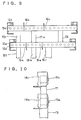
- Fig. 9 shows the portion concerning the nozzle holders viewed from the side opposite the nozzles
- Fig. 10 shows the portion viewed from a side.
- the first and second nozzle holders 12a and 12b are respectively divided into three portions of 1, r and m by partition plates 16a and 16b, and those portions are respectively connected by communicating pipes 17l, 17r and 17m, and respectively provided with fuel gas supply pipes 18l, 18r and 18m.
- the burner of the present invention has one each of the second burner units 1b at both ends, as described before.
- the second burner units 1b corresponding to the nozzles 15b at both ends of the middle portion m of the second nozzle holder 12b are arranged outside adjacently to the first burner units 1a corresponding to the nozzles 15a, at both ends of the middle portion m of the first nozzle holder 12a.
- first fuel gas is fed to all the fuel gas supply pipes 18l, 18r and 18m, and supplied to the first and second nozzle holders 12a and 12b through the communicating pipes 17l, 17r and 17m, and air is supplied from the fan 14 into the air chamber 11 for combustion.
- the fuel gas supplied to the first and second nozzle holders 12a and 12b is spouted from the respective nozzles 15a and 15b toward the corresponding inlets 4a and 4b of the burner units 1a and 1b, and sucking the air around the fuel gas by the spouting energy, it is introduced into the burner bodies 2a and 2b.
- the fuel gas and air introduced into the burner bodies 2a and 2b from the inlets 4a and 4b in this way are mixed with each other while moving through the mixer tubes 5a and 5b to reach the respective flame port portions 3a and 3b, and from there they are spouted as air-fuel mixtures for combustion.
- the quantity of the fuel gas in the air-fuel mixture spouted from the flame port portions 3a of the first burner units 1a is larger than the quantity of the fuel gas in the air-fuel mixture spouted from the flame port portions 3b of the second burner units 1b.
- first flames 19a caused by the combustion of the lean fuel mixture
- second flames 19b caused by the combustion of the rich fuel mixture
- each of the first flames 19a has the second flames 19b on both sides.
- the first flames 19a are caused by the combustion of the lean fuel mixture, and are unstable when they exist alone, but since the second flames 19b, located on both sides of each of the first flames 19a are caused by the combustion of the rich fuel mixture, the stable second flames 19b act as pilot flames to stabilize the first flames 19a. Therefore, lift of the first flames 19a and oscillating combustion are difficult to develop and thus inhibits the generation of noise.
- the stability of the first flames 19a caused by the lean fuel mixture depends also on the mixing state of the air-fuel mixture, and is poor unless the air-fuel mixture is sufficiently uniformly mixed.
- the mixing distance is long enough to achieve good mixing of fuel gas and air, and even if the fuel is lean, a large quantity of a uniformly mixed air-fuel mixture can, be supplied to the flame port portions 3a. Therefore, in the burner of the present invention, the stability of the first flames 19a is also good in this regard.
- the combustion of the lean fuel mixture stabilized as described above is due to the combustion of the air rich mixture, and its cooling action keeps the temperature of the flames 19a low, which decreases the generation of NO x . Furthermore, since the quantity of the fuel gas used for combustion of the lean fuel mixture is larger than the quantity of the fuel gas used in the rich fuel mixture, the quantity of NO x generated is small compared to the quantity burned by the burner as a whole.
- the burner units located at both the extreme ends of the burner units 1a and 1b engaged in combustion are the second burner units 1b, and so as in the above mentioned combustion state, each of the first flames 19a has second flames 19b on both sides. Therefore, the action of the second flames 19b to stabilize the first flames 19a is not lost.
- each of the first flames 19a has second flames 19b on both sides, and so the action of the second flames 19b to stabilize the first flames 19a is not lost.
- the flame port area to be used for combustion can be changed stepwise without disturbing the action of the second flames 19b to stabilize the first flames 19a, and therefore the quantity of combustion can be favorably adjusted in a wide range by utilizing any known combustion quantity control means such as proportional control.
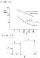
- Fig. 11 shows the NO x emission characteristic of the burner of the present invention as an example.
- the indicated air ratio values include the cooling air which may be fed around the burner units 1a and 1b.
- the parenthesized air ratio values show the values without the cooling air.
- the ratio of the quantity of fuel gas burned in the first burner units 1a, to that in the second burner units 1b is 7.5 : 2.5.
- the burner of the present invention is remarkably lower in the generation of NO x than the conventional general Bunsen burner.
- Fig. 12 shows the lift limit of the first flames 19a by the first burner units 1a in the burner of the present invention, as an example in comparison with others.
- symbol B shows the lift limit in the conventional general Bunsen burner with a flame retention mechanism, and the limit is ⁇ ⁇ 1.3.
- Symbol C shows the lift limit of the first burner units 1a when both the first and second burner units 1a and 1b are used for combustion in the burner of the present invention and the limit is ⁇ ⁇ 3.0.
- the burner of the present invention allows stable combustion of highly rich air mixture compared to the conventional general Bunsen burner and can decrease the NO x generated by the combustion of highly rich air mixture.
- Fig. 13 shows a measurement example of noise levels due to the combustion by the burners in conformity with the present invention.
- the diagram shows the noise levels for various vertical length h of the strips 6a and 6b of the flame port portions 3a and 3b, i.e., various gas flow guide channel distances of burners in conformity with the embodiment described above.
- the ratio of the gas flow guide channel distance to the equivalent diameter of the flame ports is chosen as the abscissa, and the noise level is chose as the ordinate.
- closed circles show measurements.
- the diagram also shows the measurements with burners of another example described later, i.e., burners with the gas flow guide channels formed by thick plates 22 with flame ports formed through them. The measurements are indicated by *.
- the noise level generated by combustion can be gradually lowered by elongating the gas flow guide channel distance, and that when the distance is not less than 5 times the equivalent diameter, the noise level can be practically and sufficiently lowered.
- the gas flow guide channels by the strips 6a and 6b are provided for both the flame port portions 3a and 3b of the first and second burner units 1a and 1b.
- the gas flow guide channels can be provided for the flame port portions 3a of the first burner units 1a only.
- the quantity of the air-fuel mixture spouted from the first burner units 1a is larger than that from the second burner units 1b, and in addition, the first burner units 1a which burn as an air rich mixture are liable to generate noise. So, the noise reduction effect of the gas guide channels is relatively larger in the first burner units. Therefore, even if the gas flow guide channels are provided for the flame port portions 3a of the first burner units 1a only, the burner as a whole can achieve practically sufficient noise reduction effect.
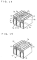
- Figs. 14, 15 and 16 show other embodiments of the burner of the present invention. They are partial perspective views showing burners with gas flow guide channels provided in the first burner units 1a only.
- the flame port portions 3a of the first burner units 1a have the gas guide channels formed by partitioning the flat channels in the upper portions of the burner bodies 2a by the strips 6a as gas flow guide plates, as in the above mentioned example, but in the second burner units 1b, the burner bodies 2b are closed at the flat upper sections u, while slit-like flame ports are formed at the tops of the upper sections u, to constitute flame port portions 3b. Therefore, the flame port portions 3b do not have any special gas flow guide channels.
- Figs. 15 and 16 show other examples. In the burners, the flame port portions 3b of the second burner units 1b are formed as in the example of Fig.
- metallic or ceramic thick plates 22 mounted at the tops of the burner bodies 2a have circular or slit-like flame ports formed to form gas flow guide channels.
- the gas flow guide channels formed by thick plates 22 with flame ports formed through them can also be provided for the second burner units 1b, though not illustrated.
- Such gas flow guide channels can also give the noise reduction effect during combustion, as shown in the measurements of Fig. 13.
- symbol 23 denotes an electrode for ignition, and 21, an electrode for flame detection.
Landscapes
- Engineering & Computer Science (AREA)
- Chemical & Material Sciences (AREA)
- Combustion & Propulsion (AREA)
- Mechanical Engineering (AREA)
- General Engineering & Computer Science (AREA)
- Gas Burners (AREA)
Abstract
Description
- The present invention relates to a burner which is low in the generation of nitrogen oxides, used in a small combustion apparatus for domestic or commercial use.
- The nitrogen oxides (NOx) in the exhaust gases from burners of various combustion apparatuses, are themselves toxic and are believed to cause acid rain and photochemical smog. So, for burners used in combustion apparatuses, various measures for decreasing the generation of NOx have been developed and utilized.
- However, these measures are mainly taken for legally regulated, large combustion apparatuses for industrial use and other services, and it cannot be said that satisfactory measures are being taken for small combustion apparatuses for domestic or commercial use, especially with respect to the noise issue.
- In the case of a large combustion apparatus, the large static pressure given by the combustion fan provides advantages such that the combustion gas and air can be easily controlled in flow. The burner is high in the degree of freedom of layout, and noise can be controlled easily. So, noise control is not difficult, and since the combustion chamber can be large, slow combustion as a means for decreasing NOx allows one to easily achieve perfect combustion. On the contrary, in the case of a small combustion apparatus, especially a small combustion apparatus for burning a large quantity, these advantages are not available and it is difficult to take measures for decreasing NOx, as compared to large combustion apparatuses.
- The objects of the present invention are to achieve a higher burner unit mounting density allowing a larger quantity of combustion and to achieve stable combustion using a lean fuel mixture to decrease nitrogen oxides and reduce noise.
- Figure 1 is a perspective view showing the first burner unit comprising the burner of the present invention as an example.
- Figure 2 is a section taken along the X-X line of Figure 1.
- Figure 3 is a section taken along the Y-Y line of Figure 1.
- Figure 4 is a perspective view showing the second burner unit comprising the burner of the present invention as an example.
- Figure 5 is a plan view showing the construction of the burner of an embodiment of the present invention with some omission.
- Figure 6 is a partially cutaway front view showing the construction of the burner of the arrangement of the present invention.
- Figures 7A and Figure 7B are an enlarged front view showing a portion of Figure 6.
- Figure 8 is a side view showing the construction embodying the present invention.
- Figure 9 is a front view showing the nozzle holders constituting the burner arrangement of the present invention, viewed from the side reverse to the nozzles.
- Figure 10 is a side view showing the nozzle holders shown in Figure 9.
- Figure 11 is a diagram showing the quantities of NOx generated by the burner embodying the present invention, in comparison with the conventional Bunsen burner.
- Figure 12 is an illustration showing the lift limit of flames of the first burner units in the burner of the present invention as an example, in comparison with others.
- Figure 13 is a diagram showing measured noise levels during combustion by the burners in conformity with the present invention.
- Figure 14 is a perspective view showing a portion of another embodiment.
- Figure 15 is a perspective view showing a portion as a further embodiment.
- Figure 16 is a perspective view showing a portion as a still further embodiment.
- 1 a
- first burner unit
- 1b
- second burner unit
- 2a, 2b
- burner body
- 3a, 3b
- flame port portion
- 4a, 4b
- inlet
- 5a, 5b
- mixer tube
- 5'a, 5'b
- throat
- 6a, 6b
- strip
- 7a, 7b
- short-slit portion
- 8a, 8b
- throttle portion
- 9
- narrowing portion
- 10
- flame retention plate
- 11
- air chamber
- 12a, 12b
- nozzle holder
- 13
- housing
- 14
- fan
- 15a, 15b
- nozzle
- 16a, 16b
- partition plate
- 171, 17r, 17m
- communicating pipe
- 181, 18r, 18m
- fuel gas supply pipe
- 19a
- first flame
- 19b
- second flame
- 20
- air-fuel mixture ejection hole
- 21
- electrode for flame detection
- 22
- thick plate
- 23
- electrode for ignition
- The means for solving the above problems are described below in reference to drawings showing embodiments.
- The burner low in the generation of nitrogen oxides of the present invention comprises respectively plural first and second burner units, said units being arranged alternately adjacently to one another; each of the burner units, being composed of a flame port portion at the top of the burner body which is vertical and flat, and an inlet for fuel gas and air at the bottom of the burner body, and a mixing channel extending from the inlet to the flame port portion; the inlets of the first burner units; being located below the inlets of the second burner units; and fuel gas spouts, being provided to correspond to the respective inlets of the first and second burner units; wherein a lean fuel mixture is supplied to the first burner units, with the quantity of fuel gas kept larger than that supplied to the second burner units, and a rich fuel mixture is supplied to the second burner units.
- In the above configuration, each of the burner bodies consists of a thin top section provided with a flame port portion at the top end and a thick bottom section provided with an inlet and a mixer tube, and each of the bottom sections of the second burner units is positioned between the top sections of the first burner units.
- Additionally, according to the present invention, a burner low in the generation of nitrogen oxides, comprising respectively plural first and second burner units, said units being arranged alternately adjacently to one another; each of the burner units being composed of a flame port portion at the top of the burner body, and an inlet for combustion gas and air at the bottom of the burner body, and a mixing channel extending from the inlet to the flame port portion; fuel gas spouts, said spouts being provided to correspond to the respective inlets of the first and second burner units; and gas flow guide channels length not less than 5 times the equivalent diameter of the flame ports, which are provided at the flame port portions of the first burner units; wherein a lean fuel mixture is supplied to the first burner units, with the quantity of fuel gas kept larger than that supplied to the second burner units, and a rich fuel mixture is supplied to the second burner units.
- In the burner low in the generation of nitrogen oxides as mentioned above, gas flow guide channels having a length not less than 5 times the equivalent diameter of the flame port, can be provided also at the flame port portions of the second burner units.
- In the above burner, the gas flow guide channels can be formed by partitioning the channels to the flame ports by gas flow guide plates or by thick plates with flame ports perforated through them.
- The inlets for fuel gas and air of the first burner units are located below the inlets of the second burner units, to present the inlets at two different stages, and the first and second burner units are arranged alternately and adjacently to one another. So, the burner units are arranged at a high density. In this case, if the top section with the flame port portion of each of the first burner units is made thinner than the bottom section with the inlet and the mixer tube of the first burner unit, and each of the lower sections of the second burner units is located between the adjacent top sections of the first burner units, then the burner units can be arranged at a high density.
- Because of the above configuration, the distance from the inlet to the flame port portion in each of the first burner units is longer than that in each of the second burner units, and so the mixing of fuel gas and air is achieved well in the first burner units. Therefore, in the first burner units, a large quantity of air-fuel mixture with lean fuel uniformly mixed, can be supplied to the flame port portions.
- In the above configuration, the lean fuel mixture is spouted for burning from the flame port portions of the first burner units, and the rich fuel mixture is spouted for burning from the flame port portions of the second burner units.
- The combustion of the lean fuel mixture alone (i.e., air rich mixture alone) is poor in the stability of flames, but since stable flames using the rich fuel mixture exist adjacently to those flames, the stable flames act as pilot flames to stabilize the flames of the air rich mixture. Therefore, neither lift of flames nor oscillating combustion occurs to cause the generation of noise.
- Since the combustion of the lean fuel mixture is stabilized by the flames of the rich fuel mixture (the combustion of air rich mixture), the temperature of the flames is kept low by the cooling action of the air rich mixture to generate less NOx. Furthermore, since the quantity of the fuel gas presented for combustion as the lean fuel mixture is larger than the quantity of the fuel gas presented as the rich fuel mixture, the quantity of the NOx generated is small compared to the quantity of combustion by the entire burner.
- The combustion noise greatly depends on the spouting condition of the air-fuel mixture from the flame ports of a burner, and if the spouting condition is turbulent, the combustion noise is large. However, in the present invention, gas flow guide channels having lengths not less than 5 times the equivalent diameter of the flame ports are provided to spout the air-fuel mixture in a sufficiently regular flow, combustion noise can be effectively reduced. Especially since the quantity of the air-fuel mixture spouted from the first burner units is larger than that from the second burner units, air rich mixture is burned. The noise reduction effect by the gas flow guide channels is achieved more than the first burner units. Therefore, even if the gas flow guide channels are provided only at the flame port portions of the first burner units, sufficient noise reduction effect can be achieved in the entire burner, but if the gas flow guide channels are provided also at the flame port portions of the second burner units, noise can be further reduced.
- Embodiments of the present invention are described below in reference to the drawings.
- Figs. 1 and 4 are perspective views showing the first and
second burner units second burner units flame port portion flat burner body inlet mixer tube inlet flame port portion burner body 2a of thefirst burner unit 1a is larger than that of theburner body 2b of thesecond burner unit 1b, and so the distance from theinlet 4a to theflame port portion 3a is longer than that of thesecond burner unit 1b. - Each of the
burner bodies second burner units flame port portion inlet mixer tube flame port portion flame port portion - According to one embodiment of the present invention, the
flame port portion 3a has twostrips 6a provided at a predetermined gap as gas flow guide plates, and thestrips 6a are held in the top section u, to form nine short-slit portions 7a, each with three slits, at predetermined spacings in the longitudinal direction. On the other hand, theflame port portion 3b has onestrip 6b as a gas flow plate in the top portion u of theburner body 2b, and thestrip 6b is held in the top section u, to form nine short-slit portions 7b, each with two slits, at predetermined spacings in the longitudinal direction. In the respectiveflame port portions strips slit portions 7a and 7b. Thestrips flame port portions strips - Each of the
inlets mixer tube inlet 4a and themixer tube 5a of thefirst burner unit 1a are larger in diameter than those of thesecond burner 1b, to allow introduction of more fuel gas and air. - On the other hand, each of the first and
second burner units throttle portion 8a or 8b across the top section u, and thefirst burner unit 1a is provided with narrowingportions 9 as gas flow guide portions at predetermined spacings upstream of thethrottle portion 8a. Furthermore, outside the top section u of thesecond burner unit 1b, aflame retention plate 10 is provided as shown in Fig. 7A and Fig. 7B, and to correspond to theflame retention plate 10, the top section u is provided with an air-fuelmixture ejection hole 20 for flame retention. These components are optional. - Figs. 5 to 8 show the entire structure of the burner composed of the first and
second burner units air chamber 11 and first andsecond nozzle holders - As shown in these drawings, many of the first and
second burner units flame port portions housing 13. In one embodiment, as shown in Figs. 6 and 7, the tops of theflame port portions 3a of thefirst burner units 1a are somewhat lower than those of theflame port portions 3b of thesecond burner units 1b, and are almost the same as the tops of theflame retention plates 10. As can be seen from Figs. 5 and 6, at both ends of theburner unit 1a, one each of thesecond burner units 1b is located. - As described above, the height of the
burner bodies 2a of thefirst burner units 1a are larger than the height of theburner bodies 2b of thesecond burner units 1b. So, as shown in Figs. 6 to 8, theinlets 4a of thefirst burner units 1a are arranged in one horizontal row at a position below theinlets 4b of thesecond burner units 1b. Furthermore, theinlets 4b of thesecond burner units 1b are arranged in one horizontal row between the top section u of theburner bodies 2a of thefirst burner units 1a. Therefore, even though theinlets 4a and themixer tubes 5a of thefirst burner units 1a are larger in bore, the adjacent top sections u of the first andsecond burner units second burner units - The
housing 13 has lower andupper nozzle holders inlets second burner units first nozzle holder 12a corresponding to thefirst burner units 1a and the uppersecond nozzle holder 12b corresponding to thesecond burner units 1b are provided. Thesenozzle holders air chamber 11 opened in front, andfan 14 supplies air into theair chamber 11. - The first, and
second nozzle holders gas ejection nozzles inlets nozzles inlets first burner units 1a are set to satisfy the condition that a lean fuel mixture larger in quantity of fuel gas than that for thesecond burner units 1b may be supplied to theflame port portions 3a, and the above components corresponding to thesecond burner units 1b are set to satisfy the condition that a rich fuel mixture may be supplied to theflame port portion 3b. For example, the air ratio of the air-fuel mixture supplied to theflame port portions 3a of thefirst burner units 1a can be set at λ ≒ 1.2 to 1.5 (where theoretical air ratio is λ = 1), and that of thesecond burner units 1b, at λ ≒ 0.4. Furthermore, the ratio of the fuel gas quantities supplied to the respectiveflame port portions first burner units 1a: thesecond burner units 1b = about 8 : 2 to 6: 4. However, the respective air ratios and the ratio of fuel gas quantities can also be set properly beyond the respective ranges. - Fig. 9 shows the portion concerning the nozzle holders viewed from the side opposite the nozzles, and Fig. 10 shows the portion viewed from a side. The first and
second nozzle holders partition plates 16a and 16b, and those portions are respectively connected by communicatingpipes gas supply pipes 18l, 18r and 18m. - As can be seen also from the arrangement of the
nozzles many burner units second burner units 1b at both ends, as described before. In this case, thesecond burner units 1b corresponding to thenozzles 15b at both ends of the middle portion m of thesecond nozzle holder 12b, are arranged outside adjacently to thefirst burner units 1a corresponding to thenozzles 15a, at both ends of the middle portion m of thefirst nozzle holder 12a. - In the burner of the present invention as mentioned above, at first fuel gas is fed to all the fuel
gas supply pipes 18l, 18r and 18m, and supplied to the first andsecond nozzle holders pipes fan 14 into theair chamber 11 for combustion. - The fuel gas supplied to the first and
second nozzle holders respective nozzles inlets burner units burner bodies burner bodies inlets mixer tubes flame port portions flame port portions 3a of thefirst burner units 1a a lean fuel mixture is spouted, and from theflame port portions 3b of thesecond burner units 1b, a rich fuel mixture is spouted. Furthermore, the quantity of the fuel gas in the air-fuel mixture spouted from theflame port portions 3a of thefirst burner units 1a is larger than the quantity of the fuel gas in the air-fuel mixture spouted from theflame port portions 3b of thesecond burner units 1b. - By such supply of air-fuel mixtures, flames (
first flames 19a) caused by the combustion of the lean fuel mixture, are formed above theflame port portions 3a of thefirst burner units 1a, and the flames (second flames 19b) caused by the combustion of the rich fuel mixture are formed above theflame port portions 3b of thesecond burner units 1b. In this case, since thesecond burner units 1b are located at both ends of theburner unit 1a, each of thefirst flames 19a has thesecond flames 19b on both sides. - The
first flames 19a are caused by the combustion of the lean fuel mixture, and are unstable when they exist alone, but since thesecond flames 19b, located on both sides of each of thefirst flames 19a are caused by the combustion of the rich fuel mixture, the stablesecond flames 19b act as pilot flames to stabilize thefirst flames 19a. Therefore, lift of thefirst flames 19a and oscillating combustion are difficult to develop and thus inhibits the generation of noise. - The stability of the
first flames 19a caused by the lean fuel mixture depends also on the mixing state of the air-fuel mixture, and is poor unless the air-fuel mixture is sufficiently uniformly mixed. - In this regard, in the burner of the present invention, as described before, since the distance from the
inlets 4a to theflame port portions 3a of thefirst burner units 1a is longer than that of thesecond burner units 1b, the mixing distance is long enough to achieve good mixing of fuel gas and air, and even if the fuel is lean, a large quantity of a uniformly mixed air-fuel mixture can, be supplied to theflame port portions 3a. Therefore, in the burner of the present invention, the stability of thefirst flames 19a is also good in this regard. - The combustion of the lean fuel mixture stabilized as described above, is due to the combustion of the air rich mixture, and its cooling action keeps the temperature of the
flames 19a low, which decreases the generation of NOx. Furthermore, since the quantity of the fuel gas used for combustion of the lean fuel mixture is larger than the quantity of the fuel gas used in the rich fuel mixture, the quantity of NOx generated is small compared to the quantity burned by the burner as a whole. - Then, in the above combustion state, if the supply of fuel gas from the fuel gas supply pipe 18r on the right-hand side in Fig. 9 is stopped, to stop the supply of fuel gas to the right-hand portion r of the first and
second nozzle holder second burner units nozzles second burner units nozzles nozzle holders - The burner units located at both the extreme ends of the
burner units second burner units 1b, and so as in the above mentioned combustion state, each of thefirst flames 19a hassecond flames 19b on both sides. Therefore, the action of thesecond flames 19b to stabilize thefirst flames 19a is not lost. - Subsequently, if the supply of fuel gas from the left combustion gas supply pipe 18l is also stopped in the above combustion state, only the first and
second burner units second nozzle holders first flames 19a hassecond flames 19b on both sides, and so the action of thesecond flames 19b to stabilize thefirst flames 19a is not lost. - In the embodiment described above, the flame port area to be used for combustion can be changed stepwise without disturbing the action of the
second flames 19b to stabilize thefirst flames 19a, and therefore the quantity of combustion can be favorably adjusted in a wide range by utilizing any known combustion quantity control means such as proportional control. - Fig. 11 shows the NOx emission characteristic of the burner of the present invention as an example. In this example using the illustrated burner, the diagram shows the relation between the air ratio of the burner as a whole chosen as the abscissa achieved by adjusting the air ratio of the lean fuel mixture in the
first burner units 1a, and the quantity of NOx generated by such burning while the air ratio of the rich fuel mixture in thesecond burner units 1b is set at λ = 0.4 to 0.7. The indicated air ratio values include the cooling air which may be fed around theburner units first burner units 1a, to that in thesecond burner units 1b is 7.5 : 2.5. - From the diagram, it can be seen that the burner of the present invention is remarkably lower in the generation of NOx than the conventional general Bunsen burner.
- Fig. 12 shows the lift limit of the
first flames 19a by thefirst burner units 1a in the burner of the present invention, as an example in comparison with others. - Symbol A shows the lift limit of the
first burner units 1a achieved when the lean fuel mixture is supplied to thefirst burner units 1a without the flame retention by the second flames of thesecond burner units 1b in the burner of the present invention, and the limit is λ = about 0.7. On the contrary, symbol B shows the lift limit in the conventional general Bunsen burner with a flame retention mechanism, and the limit is λ ≒ 1.3. Symbol C shows the lift limit of thefirst burner units 1a when both the first andsecond burner units - From the above, it can be seen that the burner of the present invention allows stable combustion of highly rich air mixture compared to the conventional general Bunsen burner and can decrease the NOx generated by the combustion of highly rich air mixture.
- Fig. 13 shows a measurement example of noise levels due to the combustion by the burners in conformity with the present invention. The diagram shows the noise levels for various vertical length h of the
strips flame port portions thick plates 22 with flame ports formed through them. The measurements are indicated by *. - From the diagram, it can be seen that the noise level generated by combustion can be gradually lowered by elongating the gas flow guide channel distance, and that when the distance is not less than 5 times the equivalent diameter, the noise level can be practically and sufficiently lowered.
- In this embodiment, the gas flow guide channels by the
strips flame port portions second burner units flame port portions 3a of thefirst burner units 1a only. In the burner of the present invention, the quantity of the air-fuel mixture spouted from thefirst burner units 1a is larger than that from thesecond burner units 1b, and in addition, thefirst burner units 1a which burn as an air rich mixture are liable to generate noise. So, the noise reduction effect of the gas guide channels is relatively larger in the first burner units. Therefore, even if the gas flow guide channels are provided for theflame port portions 3a of thefirst burner units 1a only, the burner as a whole can achieve practically sufficient noise reduction effect. - Figs. 14, 15 and 16 show other embodiments of the burner of the present invention. They are partial perspective views showing burners with gas flow guide channels provided in the
first burner units 1a only. - In the burner of Fig. 14, the
flame port portions 3a of thefirst burner units 1a have the gas guide channels formed by partitioning the flat channels in the upper portions of theburner bodies 2a by thestrips 6a as gas flow guide plates, as in the above mentioned example, but in thesecond burner units 1b, theburner bodies 2b are closed at the flat upper sections u, while slit-like flame ports are formed at the tops of the upper sections u, to constituteflame port portions 3b. Therefore, theflame port portions 3b do not have any special gas flow guide channels. Figs. 15 and 16 show other examples. In the burners, theflame port portions 3b of thesecond burner units 1b are formed as in the example of Fig. 14, but in theflame port portions 3a of thefirst burner units 1a, metallic or ceramicthick plates 22 mounted at the tops of theburner bodies 2a have circular or slit-like flame ports formed to form gas flow guide channels. The gas flow guide channels formed bythick plates 22 with flame ports formed through them can also be provided for thesecond burner units 1b, though not illustrated. Such gas flow guide channels can also give the noise reduction effect during combustion, as shown in the measurements of Fig. 13. - In the drawings referred to above,
symbol 23 denotes an electrode for ignition, and 21, an electrode for flame detection. - The present invention constructed as described above has the following effects:
- 1. Since the first burner units for burning a lean fuel mixture and the second burner units for burning a rich fuel mixture can be mounted alteratively at a high density, a burner, small in size but large in quantity of combustion, can be obtained.
- 2. Since the quantity of fuel gas used in the combustion of air rich mixture is relatively larger, the quantity of NOx generated is smaller for the quantity of combustion by the burner as a whole.
- 3. Since the combustion of the air rich mixture can be effected to be stable without causing lift of flames and oscillating combustion, the generation of noise can be inhibited.
- 4. The gas flow guide channels formed at the flame port portions can further inhibit the generation of noise.
- 5. The distance from the inlet to the flame port portion in each of the first burner units is longer than that in each of the second burner units, and so the mixing of the fuel gas and air is achieved well in the first burner units. Therefore, in the first burner units, a large quantity of air-fuel mixture with lean fuel uniformly mixed can be supplied to the flame port portions.
- 6. The lean fuel mixture is obtained by mixing fuel gas and air at each burner unit. So, even if a back fire occurs due to insufficient mixing caused by clogging, etc., it is localized, and large noise and damage can be prevented.
- 7. When we use metallic strips as gas flow guide a cost-increase does not occur, because metal is cheap compared to ceramic material.
Claims (12)
- A burner low in the generation of nitrogen oxides, comprising respectively plural first and second burner units, being arranged alternately adjacently to one another; each of the burner units, being composed of a flame port portion at the top of the burner body which is vertical and flat, an inlet for fuel gas and air at the bottom of the burner body, and a mixing channel extending from the inlet to the flame port portion; the inlets of the first-burner units, being located below the inlets of the second burner units; and fuel gas spouts, beings provided to correspond to the respective inlets of the first and second burner units; wherein a lean fuel mixture is supplied to the first burner units, with the quantity of fuel gas kept larger than that supplied to the second burner units, and a rich fuel mixture is supplied to the second burner units.
- A burner low in the generation of nitrogen oxides, according to Claim 1, wherein each of the burner bodies consists of a thin top section with a flame port portion at the top end and a thick bottom section with an inlet and a mixer tube, and each of the bottom sections of the secondary burner units is positioned between the top sections of the first burner units.
- A burner low in the generation of nitrogen oxides, comprising respectively plural first and second burner units, said units being arranged alternately adjacent to one another; each of the burner units, being composed of a flame port portion at the top of the burner body, an inlet for fuel gas and air at the bottom of the burner body, and a mixing channel extending from the inlet to the flame port portion; fuel gas spouts, being provided to correspond to the respective inlets of the first and second burner units; and gas flow guide channels with a length not less than 5 times the equivalent diameter of the flame port, said gas flow guide channel being provided at the flame port portions of the first burner units; wherein a lean fuel mixture is supplied to the first burner units, with the quantity of fuel gas kept larger than that supplied to the second burner units, and a rich fuel mixture is supplied to the second burner units.
- A burner low in the generation of nitrogen oxides, according to Claim 3, wherein gas flow guide channels having a length not less than 5 times the equivalent diameter of the flame port are provided also at the flame port portions of the second burner units.
- A burner low in the generation of nitrogen oxides, according to Claim 3, wherein the gas flow guide channels are formed by partitioning the channels to the flame ports by gas flow guide plates.
- A burner low in the generation of nitrogen oxides, according to Claim 3, wherein the gas flow guide channels are formed by thick plates with the flame ports perforated through them.
- A burner low in the generation of nitrogen oxides, according to Claim 4, wherein the gas flow guide channels are formed by partitioning the channels to the flame ports by gas flow guide plates.
- A burner low in the generation of nitrogen oxides, according to claim 4, wherein the gas flow guide channels are formed by thick plates with the flame ports perforated through them.
- A combustion apparatus comprising in combination:
a housing;
an air chamber;
air fan means for supplying air to said air chamber;
a plurality rich fuel burning units mounted in said housing, and connected to said air chamber;
a plurality of lean fuel burning units mounted in said housing, and connected to said air chamber;
at least one rich fuel nozzle holder associated with said rich fuel burning units;
at least one lean fuel nozzle associated with said lean fuel burning units; and
wherein said rich and lean fuel burning units are alternatively located in said housing thereby providing areas of rich fuel flame on two sides of lean fuel flame. - A combustion apparatus in accordance with Claim 9, wherein the quantity of fuel supplied to said lean fuel burning units is greater than the quantity of fuel supplied to said rich fuel burning units.
- A combustion apparatus in accordance with Claim 9, wherein said fuel burning units each have a gas flame channel guide length not less than 5 times the equivalent diameter of the flame ports associated with each fuel burning unit.
- A combustion apparatus in accordance with Claim 9, further comprising gas injection nozzles for each fuel burning unit.
Applications Claiming Priority (4)
| Application Number | Priority Date | Filing Date | Title |
|---|---|---|---|
| JP272062/91 | 1991-09-24 | ||
| JP27206291A JP2768391B2 (en) | 1991-09-24 | 1991-09-24 | Low NOx burner |
| JP103326/92 | 1992-04-23 | ||
| JP4103326A JPH05296418A (en) | 1992-04-23 | 1992-04-23 | Burner with low occurrence of nitrogen oxide |
Publications (3)
| Publication Number | Publication Date |
|---|---|
| EP0534554A2 true EP0534554A2 (en) | 1993-03-31 |
| EP0534554A3 EP0534554A3 (en) | 1993-06-09 |
| EP0534554B1 EP0534554B1 (en) | 1997-03-26 |
Family
ID=26443970
Family Applications (1)
| Application Number | Title | Priority Date | Filing Date |
|---|---|---|---|
| EP92202918A Expired - Lifetime EP0534554B1 (en) | 1991-09-24 | 1992-09-23 | A burner low in the generation of nitrogen oxides and a small combustion apparatus |
Country Status (4)
| Country | Link |
|---|---|
| US (1) | US5318438A (en) |
| EP (1) | EP0534554B1 (en) |
| KR (1) | KR960012390B1 (en) |
| DE (1) | DE69218531T2 (en) |
Cited By (8)
| Publication number | Priority date | Publication date | Assignee | Title |
|---|---|---|---|---|
| EP0587456A1 (en) * | 1992-09-11 | 1994-03-16 | Rinnai Kabushiki Kaisha | A burner device and the method of making the same |
| EP0753702A1 (en) * | 1995-01-27 | 1997-01-15 | Gastar Co., Ltd. | Burner and burner unit |
| EP0967436A2 (en) * | 1998-06-23 | 1999-12-29 | Truma Gerätetechnik GmbH & Co. | Cascade-burner |
| EP1083386A1 (en) * | 1999-09-09 | 2001-03-14 | Giorgio Scanferla | Burner assembly and burner head for burning fuel/comburent gaseous mixtures |
| WO2005059437A1 (en) * | 2003-12-10 | 2005-06-30 | Worgas -Bruciatori - S.R.L. | Bladed burner with mutual ignition means |
| EP1566592A1 (en) * | 2004-02-20 | 2005-08-24 | Chaffoteaux & Maury | Improvements to atmospheric gas burners |
| FR2919348A1 (en) * | 2007-07-23 | 2009-01-30 | Centre Nat Rech Scient | Multi-point injection device for e.g. gas turbine, has diaphragms placed remote from each other, where gap between diaphragms permits phase shifting of flames formed respectively in outlet of channels in response to acoustic stress |
| US20180209640A1 (en) * | 2017-01-24 | 2018-07-26 | Rinnai Corporation | Combustion Apparatus |
Families Citing this family (27)
| Publication number | Priority date | Publication date | Assignee | Title |
|---|---|---|---|---|
| US6746236B2 (en) * | 2002-01-24 | 2004-06-08 | Noritz Corporation | Combustion apparatus |
| US20040006926A1 (en) * | 2002-07-15 | 2004-01-15 | Neeley Clifton B. | Climate controlled practice facility and method utilizing the same |
| US20090325114A1 (en) * | 2008-06-27 | 2009-12-31 | Empire Comfort Systems, Inc. | Atmospheric Burner for Gas Log Fireplace Producing Stage Combustion and Yellow Chemiluminescent Flame |
| JP5449739B2 (en) | 2008-10-17 | 2014-03-19 | 日本ゴア株式会社 | Method for producing breathable composite sheet |
| KR101025703B1 (en) * | 2009-07-22 | 2011-03-30 | 주식회사 경동나비엔 | Gas burner |
| JP2011252671A (en) * | 2010-06-03 | 2011-12-15 | Rinnai Corp | Combustion apparatus |
| CA2818208C (en) * | 2010-12-01 | 2017-08-22 | A. O. Smith Corporation | Low nox burner for a water heater |
| US9115891B2 (en) * | 2010-12-16 | 2015-08-25 | Noritz Corporation | Rich-lean combustion burner |
| US20120219920A1 (en) * | 2011-02-28 | 2012-08-30 | Noritz Corporation | Rich-lean combustion burner |
| CN103162290B (en) * | 2011-12-09 | 2016-08-03 | 株式会社能率 | Rich-lean combustion burner and burner |
| CN103185339B (en) * | 2011-12-28 | 2016-08-03 | 株式会社能率 | Rich-lean combustion burner and burner |
| US10480823B2 (en) * | 2013-11-14 | 2019-11-19 | Lennox Industries Inc. | Multi-burner head assembly |
| KR101468940B1 (en) * | 2013-11-15 | 2014-12-04 | 주식회사 경동나비엔 | Lean rich combustion apparatus |
| JP6356438B2 (en) * | 2014-03-04 | 2018-07-11 | パーパス株式会社 | Burner, combustion apparatus and combustion method |
| CN104373937B (en) * | 2014-11-13 | 2017-04-12 | 艾欧史密斯(中国)热水器有限公司 | Fuel gas premixing burner and fuel gas water heater |
| JP6563714B2 (en) * | 2015-06-29 | 2019-08-21 | リンナイ株式会社 | Combustion device |
| CN105546544B (en) * | 2015-08-07 | 2018-03-06 | 甘国玉 | A kind of energy-conservation fire row of low noise |
| MX2018007951A (en) | 2015-12-28 | 2018-11-09 | Khanania Souhel | Burner assembly and heat exchanger. |
| US11690471B2 (en) | 2015-12-28 | 2023-07-04 | Souhel Khanania | Cooking system with burner assembly and heat exchanger |
| US11346549B2 (en) | 2015-12-28 | 2022-05-31 | Souhel Khanania | Burner assembly and systems incorporating a burner assembly |
| CN105737156B (en) * | 2016-04-06 | 2017-10-27 | 甘国玉 | A kind of noise reduction emission reduction fire row |
| US20180031230A1 (en) * | 2016-07-29 | 2018-02-01 | Purpose Co., Ltd. | Burner, combustion apparatus, and combustion method |
| KR102172467B1 (en) | 2017-09-19 | 2020-11-02 | 주식회사 경동나비엔 | Flame hole structure of combusion apparatus |
| WO2020006094A1 (en) * | 2018-06-28 | 2020-01-02 | Souhel Khanania | Burner assembly and systems incorporating a burner assembly |
| KR102529871B1 (en) * | 2018-06-29 | 2023-05-09 | 주식회사 경동나비엔 | Flame hole structure of combusion apparatus |
| KR102509233B1 (en) * | 2018-07-31 | 2023-03-15 | 더블유.엘. 고어 앤드 어소시에이트스, 인코포레이티드 | polyethylene film |
| US11181265B2 (en) * | 2019-11-07 | 2021-11-23 | Rinnai Corporation | Flat burner |
Citations (6)
| Publication number | Priority date | Publication date | Assignee | Title |
|---|---|---|---|---|
| DE8633823U1 (en) * | 1986-12-18 | 1987-04-09 | Joh. Vaillant Gmbh U. Co, 5630 Remscheid | Atmospheric gas burner for controlling the air ratio of the gas-air mixture supplied to such a gas burner |
| WO1987006998A1 (en) * | 1986-05-13 | 1987-11-19 | Joh. Vaillant Gmbh U. Co | Process for operating a pre-mix gas burner |
| EP0331037A2 (en) * | 1988-02-27 | 1989-09-06 | Osaka Gas Co., Ltd. | Gas burner |
| DE3906795A1 (en) * | 1988-03-09 | 1989-09-21 | Vaillant Joh Gmbh & Co | Method for burning burnable gas/combustion air mixtures, and burner for carrying out this method |
| JPH03247908A (en) * | 1990-02-23 | 1991-11-06 | Osaka Gas Co Ltd | Gas burner |
| WO1992001196A1 (en) * | 1990-07-06 | 1992-01-23 | Worgas Bruciatori S.R.L. | Methods and apparatus for gas combustion |
Family Cites Families (2)
| Publication number | Priority date | Publication date | Assignee | Title |
|---|---|---|---|---|
| JPS55110813A (en) * | 1979-02-17 | 1980-08-26 | Atago Seisakusho:Kk | High density burner |
| CA2005415C (en) * | 1989-01-10 | 1994-03-01 | Willie H. Best | High efficiency gas burner assembly |
-
1992
- 1992-09-23 EP EP92202918A patent/EP0534554B1/en not_active Expired - Lifetime
- 1992-09-23 DE DE69218531T patent/DE69218531T2/en not_active Expired - Fee Related
- 1992-09-24 KR KR1019920017407A patent/KR960012390B1/en not_active IP Right Cessation
- 1992-09-24 US US07/950,318 patent/US5318438A/en not_active Expired - Lifetime
Patent Citations (6)
| Publication number | Priority date | Publication date | Assignee | Title |
|---|---|---|---|---|
| WO1987006998A1 (en) * | 1986-05-13 | 1987-11-19 | Joh. Vaillant Gmbh U. Co | Process for operating a pre-mix gas burner |
| DE8633823U1 (en) * | 1986-12-18 | 1987-04-09 | Joh. Vaillant Gmbh U. Co, 5630 Remscheid | Atmospheric gas burner for controlling the air ratio of the gas-air mixture supplied to such a gas burner |
| EP0331037A2 (en) * | 1988-02-27 | 1989-09-06 | Osaka Gas Co., Ltd. | Gas burner |
| DE3906795A1 (en) * | 1988-03-09 | 1989-09-21 | Vaillant Joh Gmbh & Co | Method for burning burnable gas/combustion air mixtures, and burner for carrying out this method |
| JPH03247908A (en) * | 1990-02-23 | 1991-11-06 | Osaka Gas Co Ltd | Gas burner |
| WO1992001196A1 (en) * | 1990-07-06 | 1992-01-23 | Worgas Bruciatori S.R.L. | Methods and apparatus for gas combustion |
Non-Patent Citations (1)
| Title |
|---|
| PATENT ABSTRACTS OF JAPAN vol. 16, no. 41 (M-1206)31 January 1992 & JP-03 247 908 ( OSAKA GAS ) 6 November 1991 * |
Cited By (14)
| Publication number | Priority date | Publication date | Assignee | Title |
|---|---|---|---|---|
| EP0587456A1 (en) * | 1992-09-11 | 1994-03-16 | Rinnai Kabushiki Kaisha | A burner device and the method of making the same |
| US5525054A (en) * | 1992-09-11 | 1996-06-11 | Rinnai Kabushiki Kaisha | Burner device and a method of making the same |
| US5661905A (en) * | 1992-09-11 | 1997-09-02 | Rinnai Kabushiki Kaisha | Method of making a burner device |
| EP0753702A1 (en) * | 1995-01-27 | 1997-01-15 | Gastar Co., Ltd. | Burner and burner unit |
| EP0753702A4 (en) * | 1995-01-27 | 1999-03-03 | Gastar Co Ltd | Burner and burner unit |
| EP0967436A3 (en) * | 1998-06-23 | 2000-02-09 | Truma Gerätetechnik GmbH & Co. | Cascade-burner |
| EP0967436A2 (en) * | 1998-06-23 | 1999-12-29 | Truma Gerätetechnik GmbH & Co. | Cascade-burner |
| EP1083386A1 (en) * | 1999-09-09 | 2001-03-14 | Giorgio Scanferla | Burner assembly and burner head for burning fuel/comburent gaseous mixtures |
| WO2005059437A1 (en) * | 2003-12-10 | 2005-06-30 | Worgas -Bruciatori - S.R.L. | Bladed burner with mutual ignition means |
| EP1566592A1 (en) * | 2004-02-20 | 2005-08-24 | Chaffoteaux & Maury | Improvements to atmospheric gas burners |
| FR2866696A1 (en) * | 2004-02-20 | 2005-08-26 | Chaffoteaux Et Maury | IMPROVEMENTS ON ATMOSPHERIC TYPE GAS BURNERS |
| FR2919348A1 (en) * | 2007-07-23 | 2009-01-30 | Centre Nat Rech Scient | Multi-point injection device for e.g. gas turbine, has diaphragms placed remote from each other, where gap between diaphragms permits phase shifting of flames formed respectively in outlet of channels in response to acoustic stress |
| US20180209640A1 (en) * | 2017-01-24 | 2018-07-26 | Rinnai Corporation | Combustion Apparatus |
| US10571120B2 (en) * | 2017-01-24 | 2020-02-25 | Rinnai Corporation | Combustion apparatus |
Also Published As
| Publication number | Publication date |
|---|---|
| KR960012390B1 (en) | 1996-09-20 |
| EP0534554B1 (en) | 1997-03-26 |
| DE69218531D1 (en) | 1997-04-30 |
| EP0534554A3 (en) | 1993-06-09 |
| US5318438A (en) | 1994-06-07 |
| DE69218531T2 (en) | 1997-07-03 |
| KR930006367A (en) | 1993-04-21 |
Similar Documents
| Publication | Publication Date | Title |
|---|---|---|
| EP0534554B1 (en) | A burner low in the generation of nitrogen oxides and a small combustion apparatus | |
| JPH0623604B2 (en) | Gas burner | |
| JP2630205B2 (en) | Combustion equipment | |
| KR0126902B1 (en) | Low nitrogen oxide rurner | |
| US6537064B1 (en) | Flow director for line burner | |
| JPH05296418A (en) | Burner with low occurrence of nitrogen oxide | |
| JP2839049B2 (en) | Burner unit | |
| JP3151761B2 (en) | Combustion equipment | |
| JP3244812B2 (en) | Combustion equipment | |
| JP3242366B2 (en) | Combustion equipment | |
| JPH0330662Y2 (en) | ||
| JPH0424258Y2 (en) | ||
| JPH0443698Y2 (en) | ||
| JPS6354510A (en) | Gas burner | |
| JPH05141629A (en) | Burner | |
| JP3116007B2 (en) | Concentration combustion device | |
| JP2768391B2 (en) | Low NOx burner | |
| JPH04236004A (en) | Burner | |
| JP3012473B2 (en) | Combustion equipment | |
| JP3101246B2 (en) | Combustion equipment | |
| JP2956243B2 (en) | Combustion equipment | |
| JPH0663626B2 (en) | Premixed gas burner | |
| JPH07318019A (en) | Burner | |
| JPH04124512A (en) | Low nox burner | |
| JPH07103424A (en) | Thick and thin fuel combustion device |
Legal Events
| Date | Code | Title | Description |
|---|---|---|---|
| PUAI | Public reference made under article 153(3) epc to a published international application that has entered the european phase |
Free format text: ORIGINAL CODE: 0009012 |
|
| AK | Designated contracting states |
Kind code of ref document: A2 Designated state(s): DE FR GB IT NL |
|
| PUAL | Search report despatched |
Free format text: ORIGINAL CODE: 0009013 |
|
| AK | Designated contracting states |
Kind code of ref document: A3 Designated state(s): DE FR GB IT NL |
|
| 17P | Request for examination filed |
Effective date: 19931020 |
|
| 17Q | First examination report despatched |
Effective date: 19940914 |
|
| GRAG | Despatch of communication of intention to grant |
Free format text: ORIGINAL CODE: EPIDOS AGRA |
|
| GRAH | Despatch of communication of intention to grant a patent |
Free format text: ORIGINAL CODE: EPIDOS IGRA |
|
| GRAH | Despatch of communication of intention to grant a patent |
Free format text: ORIGINAL CODE: EPIDOS IGRA |
|
| GRAA | (expected) grant |
Free format text: ORIGINAL CODE: 0009210 |
|
| AK | Designated contracting states |
Kind code of ref document: B1 Designated state(s): DE FR GB IT NL |
|
| ITF | It: translation for a ep patent filed | ||
| REF | Corresponds to: |
Ref document number: 69218531 Country of ref document: DE Date of ref document: 19970430 |
|
| ET | Fr: translation filed | ||
| PLBE | No opposition filed within time limit |
Free format text: ORIGINAL CODE: 0009261 |
|
| STAA | Information on the status of an ep patent application or granted ep patent |
Free format text: STATUS: NO OPPOSITION FILED WITHIN TIME LIMIT |
|
| 26N | No opposition filed | ||
| REG | Reference to a national code |
Ref country code: GB Ref legal event code: IF02 |
|
| PGFP | Annual fee paid to national office [announced via postgrant information from national office to epo] |
Ref country code: NL Payment date: 20060917 Year of fee payment: 15 |
|
| PGFP | Annual fee paid to national office [announced via postgrant information from national office to epo] |
Ref country code: GB Payment date: 20060920 Year of fee payment: 15 |
|
| PGFP | Annual fee paid to national office [announced via postgrant information from national office to epo] |
Ref country code: DE Payment date: 20060922 Year of fee payment: 15 |
|
| PGFP | Annual fee paid to national office [announced via postgrant information from national office to epo] |
Ref country code: IT Payment date: 20060930 Year of fee payment: 15 |
|
| GBPC | Gb: european patent ceased through non-payment of renewal fee |
Effective date: 20070923 |
|
| PG25 | Lapsed in a contracting state [announced via postgrant information from national office to epo] |
Ref country code: NL Free format text: LAPSE BECAUSE OF NON-PAYMENT OF DUE FEES Effective date: 20080401 |
|
| NLV4 | Nl: lapsed or anulled due to non-payment of the annual fee |
Effective date: 20080401 |
|
| PG25 | Lapsed in a contracting state [announced via postgrant information from national office to epo] |
Ref country code: DE Free format text: LAPSE BECAUSE OF NON-PAYMENT OF DUE FEES Effective date: 20080401 |
|
| PGFP | Annual fee paid to national office [announced via postgrant information from national office to epo] |
Ref country code: FR Payment date: 20080114 Year of fee payment: 16 |
|
| REG | Reference to a national code |
Ref country code: FR Ref legal event code: ST Effective date: 20080531 |
|
| PG25 | Lapsed in a contracting state [announced via postgrant information from national office to epo] |
Ref country code: FR Free format text: LAPSE BECAUSE OF NON-PAYMENT OF DUE FEES Effective date: 20071001 |
|
| PG25 | Lapsed in a contracting state [announced via postgrant information from national office to epo] |
Ref country code: GB Free format text: LAPSE BECAUSE OF NON-PAYMENT OF DUE FEES Effective date: 20070923 |
|
| PG25 | Lapsed in a contracting state [announced via postgrant information from national office to epo] |
Ref country code: IT Free format text: LAPSE BECAUSE OF NON-PAYMENT OF DUE FEES Effective date: 20070923 |