EP0534262A2 - Open architecture video pipe system - Google Patents
Open architecture video pipe system Download PDFInfo
- Publication number
- EP0534262A2 EP0534262A2 EP92115679A EP92115679A EP0534262A2 EP 0534262 A2 EP0534262 A2 EP 0534262A2 EP 92115679 A EP92115679 A EP 92115679A EP 92115679 A EP92115679 A EP 92115679A EP 0534262 A2 EP0534262 A2 EP 0534262A2
- Authority
- EP
- European Patent Office
- Prior art keywords
- board
- display system
- bus
- slots
- video
- Prior art date
- Legal status (The legal status is an assumption and is not a legal conclusion. Google has not performed a legal analysis and makes no representation as to the accuracy of the status listed.)
- Granted
Links
Images


Classifications
-
- H—ELECTRICITY
- H04—ELECTRIC COMMUNICATION TECHNIQUE
- H04N—PICTORIAL COMMUNICATION, e.g. TELEVISION
- H04N5/00—Details of television systems
- H04N5/44—Receiver circuitry for the reception of television signals according to analogue transmission standards
-
- G—PHYSICS
- G06—COMPUTING; CALCULATING OR COUNTING
- G06F—ELECTRIC DIGITAL DATA PROCESSING
- G06F13/00—Interconnection of, or transfer of information or other signals between, memories, input/output devices or central processing units
- G06F13/38—Information transfer, e.g. on bus
- G06F13/382—Information transfer, e.g. on bus using universal interface adapter
- G06F13/385—Information transfer, e.g. on bus using universal interface adapter for adaptation of a particular data processing system to different peripheral devices
Abstract
Description
- This invention relates to displays and video systems, more particularly to architectures for them.
- Recently, there has been heightened interest in a system that is portable between computers and television for video display. With the advent of multi-media computing, such as being developed at Microsoft, Intel, Apple, etc., users can access real-time video images and display them on a portion of the screen. But the architecture of the computer is not one that can support a full screen real-time video image.
- Currently, televisions are portable between television and computer displays. Indeed, some users even used an extra television as a monitor rather than buy a dedicated monitor. But television are limited in their support of such configurations. There are many problems, but the most significant is bandwidth.
- Televisions are designed to receive a large bandwidth signal from an antenna or a cable connection. These signals are sent to a tuner, which isolates the relevant channel, or channels, and sends them to the appropriate output, such as the display, the VCR, or both. Computers do not have a tuner, therefore they cannot handle the large bandwidth signal. On the other hand, the television is merely set up, usually via an adapter, to receive signals from the computer as if it were a dedicated channel.
- Portability between the two systems would allow for many advantages. Interactive television would be given a whole range of possibilities. For example, a viewer may have, in addition, or instead of a remote control, a remote keyboard that can allow he or she to save television broadcasts, movies, or other important information. Also, the computer user can access broadcast, or recorded, television while working on the computer to create such things as multi-media presentations.
- The television and computer industries have not progressed to a point where this is going to be immediately possible. This limitation is not one of technology, but one where neither industry is willing to compromise any standards or non-portable functions. Ideally, television and computer manufacturers need a way to build a system that is functional now, and flexible to be updated for the future.
- Objects and advantages will be obvious, and will in part appear hereinafter and will be accomplished by the present invention which provides a portable architecture for video graphics adaptation and for television. A system with card slots is provided by the invention. The card slots can be filled with various cards including, but not limited to, tuner cards, video cassette controller cards, video graphics card for computers, special effects cards, and remote control input cards. It is one advantage of the invention to provide one system that can be either used as a television or a computer display, or both.
- For a complete understanding of the invention, and the advantages thereof, reference is now made to the following description in conjunction with the accompanying drawings, in which:
- FIGURE 1 shows a bare bus structure.
- FIGURE 2 shows an empty receiver architecture.
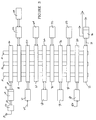
- FIGURE 3 shows a possible configuration of a populated receiver architecture.
- In order to effect a complete compatibility between computers and televisions, a chassis must be designed to accommodate both functions. The chassis must include some type of architecture that can be configured many different ways. One possible architecture to be contained in the chassis is shown in Figure 1.
- Figure 1 shows a possible bus structure that would be included in the television/monitor chassis. Typically, this would be on a board that is the equivalent to a personal computer's motherboard. Shown in this example are three busses. The number of busses used is only limited by the designers' desires to break down the main functions of the television/monitor into subfunctions.
- In this example, there are three busses: an
audio bus 10; avideo bus 12; and acontrol bus 14. The busses are on the surface of the board, andedge connectors Edge connector 16 is designated asconnection edge connector 20 isconnection N. Connector 22 is connection N+1. Additionally, the functions could all be included in one bus structure. - Figure 2 shows an empty architecture receiver. The bus structure has been integrated with a television receiving circuit, and a video circuit card to drive the display. The television signal comes into the system via
antenna 24, is passed to atuner 26 which in turn sends the signal tovideo formatter 30 alongbus 28. The video formatter has a analog-to-digital converter 32 attached, which converts the incoming signal to be placed on the busses. The digitized signal is sent to the busses vialines 34, intoslot 16 which will contain a card. Alternatively, all of the preceding functions could be contained on the card itself, or contained on the motherboard itself, and connected directly to the bus through traces on the board. The card inslot 16 would have circuitry upon it to divide the incoming signal up into a control signal, an audio signal, and a video signal in this example. - At the other end of the receiver, connected to
slot 22, is the circuitry to control the output of the display.Bus 38 connects to the connector inslot 22, and communicates the output to thedriver 36.Driver 36 has a digital-to-analog converter attached which converts the data necessary to drive the cathode ray tube. If a digital display, such as a deformable mirror device television were to be used, the digital-to-analog converter could be eliminated. In this case, no bus switching circuitry need be provided. The tuner and video card could be hard configured to send and receive on the same partition of the video bus. - Figure 3 shows one of many possible configurations of a fully populated receiver. In addition to the cards already mentioned, other possibilities are: a
memory processor 52, withremote input block 54, inslot 18. In slot 56, a remote input and output module 61, withinput line 60. The image processor 64 for the display could be inslot 62. Storage controller 68, which could control an external tape drive, is shown inslot 66. Aspecial effects card 72, for controlling such things as windowed screens, slow motion, etc., is inslot 70.Slot 76 holds the controller card for the hardcopy output device 78, such as a printer, from the computer. Slot 80 contains a card for controlling anoptional display module 82. Audio control of the system is on the card inslot 20, which controls the audio driver 84, with itsinput 86. - These slots could be placed inside the chassis, much like current personal computer practice, or inside the chassis but easily accessible like current video game practice, or totally open on the enclosure surface. These different physical architectures allow hardware/electrical control architectures to serve different markets.
- The overall population of the chassis can be effected in a cartridge format, not unlike home video games. There are many different scenarios. One is that the consumer decides in the electronics store what extras he or she wants. The salesman then populates the slots with the appropriate cartridges, which contain the controllers mentioned above. Some consumers may decide to just buy the chassis, and populate the slots themselves. This system also lends itself to upgrades very easily.
- The assignments of slots is completely arbitrary. Likewise, the assignments of bus partitions could also be done in many ways. The partitions could be preassigned and labelled, so when the consumer decides to upgrade, he or she merely buys the cartridge and switch selects it to the appropriate partitions. With a little more complex controllers, the partitions could be universal. The cards would have an identifier in their hardware that allowed them to know which partition on the bus is for them. Additionally, the cards could have some type of acknowledger in them to let the system control card, or the tuner card, know what partition they are on. Partition switching or selecting on each card could be hardwired by jumper, for the lowest cost, local switch selectable, for medium cost, or remotely switch selectable at highest cost. Any external connectors could be mounted on the end of the cartridge away from the end connector, or alternately in a panel or door, such that when the panel or door was closed, the connectors made the appropriate contact through the door. All methods are mutually compatible and can be used simultaneously in the same system, and no method requires expensive bus demultiplexing circuitry since each card uses a dedicated portion of the bus.
- The advantages of such a system are numerous. Some of these are modularity, expandability, and portability. A modular television/monitor console is easier to upgrade and to repair. When a standard for HDTV is finally decided, if it requires a change in the tuner, or a change in the display, just the tuner card, or the display needs to be changed. If the display is spatial light modulator driven, with binary inputs, it may be that the controller for the display be changed, not the entire CRT module. When HDTV becomes a reality, a new controller, or whatever is required to allow the upgrade will be easier to install. This system is portable between television and video graphics. It can be used now, and in the future.
- Thus, although there has been described to this point a particular embodiment for a television/monitor, it is not intended that such specific references be considered as limitations upon the scope of this invention except in-so-far as set forth in the following claims.
Claims (20)
- A display system architecture including:a. at least one bus operable to transfer digital signals, wherein said signals comprise audio, video and control data;b. a plurality of slots traversing the width of said bus, said slots capable of making electrical connection with at least one external circuit board.
- The display system as claimed in claim 1, wherein said at least one bus further comprises three buses, one bus for audio data, one bus for video data and one bus for control data.
- The display system as claimed in claim 1, wherein one of said at least one board is a television tuner circuit operable to receive broadcast television of a standard format.
- The display system as claimed in claim 1, wherein one of said at least one board is a cathode ray tube driver board.
- The display system as claimed in claim 1, wherein one of said at least one board is a spatial light modulator display driver board.
- The display system as claimed in claim 1, wherein one of said at least one board is a video recorder control board.
- The display system as claimed in claim 1, wherein one of said at least one board is a memory board.
- The display system as claimed in claim 1, wherein one of said at least one board is an optional display driver board.
- The display system as claimed in claim 1, wherein one of said at least one board is a special effects board.
- The display system as claimed in claim 1, wherein one of said at least one board is a remote control reception processor board.
- The display system as claimed in claim 1, wherein one of said at least one board is an audio control board.
- The display system as claimed in claim 1, wherein one of said at least one board is a hard copy controller.
- A display system architecture comprising:a. an audio bus;b. a video bus parallel to said audio bus;c. a control bus parallel to said audio bus and said video bus;d. a plurality of slots traversing the width of said bus, said slots capable of making electrical connection with at least one external circuit board;e. a television tuner circuit in one of said slots, operable to receive and process a standardized broadcast signal;f. a video graphics adapter in another of said slots, operable to process data from a computer for display; andg. a display driver card in another of said slots, operable to produce an image upon receipt of said processed standardized broadcast signal, or said video graphics signal.
- The display system as claimed in claim 13 wherein another of said slots contains a video player/recorder controller.
- The display system as claimed in claim 13 wherein another of said slots contains a memory controller circuit.
- The displays system as claimed in claim 13 wherein another of said slots contains a special effects video processor card.
- The display system as claimed in claim 13 wherein another of said slots contains a remote control input processor card.
- The display system as claimed in claim 13 wherein another of said slots contains an audio controller card.
- The display system as claimed in claim 13 wherein another of said slots contains a hard copy controller card.
- The display system as claimed in claim 19 wherein said hard copy controller card is further connected to a printer.
Applications Claiming Priority (2)
| Application Number | Priority Date | Filing Date | Title |
|---|---|---|---|
| US76688591A | 1991-09-27 | 1991-09-27 | |
| US766885 | 1991-09-27 |
Publications (3)
| Publication Number | Publication Date |
|---|---|
| EP0534262A2 true EP0534262A2 (en) | 1993-03-31 |
| EP0534262A3 EP0534262A3 (en) | 1997-02-05 |
| EP0534262B1 EP0534262B1 (en) | 2002-01-16 |
Family
ID=25077826
Family Applications (1)
| Application Number | Title | Priority Date | Filing Date |
|---|---|---|---|
| EP92115679A Expired - Lifetime EP0534262B1 (en) | 1991-09-27 | 1992-09-14 | Open architecture video pipe system |
Country Status (4)
| Country | Link |
|---|---|
| EP (1) | EP0534262B1 (en) |
| JP (1) | JP3373559B2 (en) |
| KR (1) | KR930007240A (en) |
| DE (1) | DE69232346T2 (en) |
Cited By (6)
| Publication number | Priority date | Publication date | Assignee | Title |
|---|---|---|---|---|
| WO1996019895A1 (en) * | 1994-12-22 | 1996-06-27 | Philips Electronics N.V. | An interface system for a television receiver |
| EP0748125A1 (en) * | 1995-06-07 | 1996-12-11 | Texas Instruments Incorporated | Improvements in or relating to image display systems |
| EP0784402A3 (en) * | 1996-01-10 | 1999-07-07 | Matsushita Electric Industrial Co., Ltd. | Television receiver |
| GB2364609A (en) * | 2000-05-06 | 2002-01-30 | Samsung Electronics Co Ltd | Providing removably connected extension boards in a multimedia system |
| GB2377574A (en) * | 2001-07-12 | 2003-01-15 | Graeme Roy Smith | Modular software/firmware definable video server |
| EP0957641A3 (en) * | 1998-05-13 | 2004-10-06 | Sony Corporation | Digital signal processing apparatus |
Citations (2)
| Publication number | Priority date | Publication date | Assignee | Title |
|---|---|---|---|---|
| JPS62219881A (en) * | 1986-03-20 | 1987-09-28 | Fujitsu General Ltd | Multifunctional tv receiving set |
| WO1991015920A1 (en) * | 1990-04-09 | 1991-10-17 | Interactive Media Technologies, Inc. | Interconnection and control of multiple audio and video media devices |
-
1992
- 1992-09-14 EP EP92115679A patent/EP0534262B1/en not_active Expired - Lifetime
- 1992-09-14 DE DE69232346T patent/DE69232346T2/en not_active Expired - Fee Related
- 1992-09-25 JP JP25684792A patent/JP3373559B2/en not_active Expired - Fee Related
- 1992-09-26 KR KR1019920017613A patent/KR930007240A/en not_active Application Discontinuation
Patent Citations (2)
| Publication number | Priority date | Publication date | Assignee | Title |
|---|---|---|---|---|
| JPS62219881A (en) * | 1986-03-20 | 1987-09-28 | Fujitsu General Ltd | Multifunctional tv receiving set |
| WO1991015920A1 (en) * | 1990-04-09 | 1991-10-17 | Interactive Media Technologies, Inc. | Interconnection and control of multiple audio and video media devices |
Non-Patent Citations (1)
| Title |
|---|
| PATENT ABSTRACTS OF JAPAN vol. 12, no. 85 (E-591), 17 March 1988 & JP-A-62 219881 (FUJITSU GENERAL LIMITED), 28 September 1987, * |
Cited By (8)
| Publication number | Priority date | Publication date | Assignee | Title |
|---|---|---|---|---|
| WO1996019895A1 (en) * | 1994-12-22 | 1996-06-27 | Philips Electronics N.V. | An interface system for a television receiver |
| EP0748125A1 (en) * | 1995-06-07 | 1996-12-11 | Texas Instruments Incorporated | Improvements in or relating to image display systems |
| EP0784402A3 (en) * | 1996-01-10 | 1999-07-07 | Matsushita Electric Industrial Co., Ltd. | Television receiver |
| US5982449A (en) * | 1996-01-10 | 1999-11-09 | Matsushita Electric Industrial Co., Ltd. | Television receiver that provides gradation correction using a CPU |
| EP0957641A3 (en) * | 1998-05-13 | 2004-10-06 | Sony Corporation | Digital signal processing apparatus |
| GB2364609A (en) * | 2000-05-06 | 2002-01-30 | Samsung Electronics Co Ltd | Providing removably connected extension boards in a multimedia system |
| DE10121777B4 (en) * | 2000-05-06 | 2006-08-10 | Samsung Electronics Co., Ltd., Suwon | Multimedia device whose functions can be extended and procedures for extending the functions |
| GB2377574A (en) * | 2001-07-12 | 2003-01-15 | Graeme Roy Smith | Modular software/firmware definable video server |
Also Published As
| Publication number | Publication date |
|---|---|
| EP0534262B1 (en) | 2002-01-16 |
| KR930007240A (en) | 1993-04-22 |
| EP0534262A3 (en) | 1997-02-05 |
| JPH075859A (en) | 1995-01-10 |
| DE69232346D1 (en) | 2002-02-21 |
| DE69232346T2 (en) | 2002-09-19 |
| JP3373559B2 (en) | 2003-02-04 |
Similar Documents
| Publication | Publication Date | Title |
|---|---|---|
| CN1190730C (en) | Method and apparatus for including self-describing information within devices | |
| EP0788048B1 (en) | Display apparatus interface | |
| EP1156671A2 (en) | Audio/video apparatus | |
| US6341375B1 (en) | Video on demand DVD system | |
| CA2748888C (en) | Tv function expansion component using gold finger connector | |
| US20100064076A1 (en) | Switching apparatus and displaying system | |
| WO2001058133A2 (en) | Multi-functional home entertainment system utilizing device bay technology | |
| EP1596581B1 (en) | A display device with data reading means | |
| CA1318391C (en) | Television system user-accessible component display apparatus | |
| EP2375730A1 (en) | Television capable of implementing function extension | |
| US5727191A (en) | Monitor adapter | |
| EP1938587A1 (en) | Appliance and method for processing a plurality of high resolution multimedial operative functions and programs, which appliance is integrated with a television receiver screen, as well as remote control system and remote control device and method to set and display such multimedial operative functi | |
| US20040247280A1 (en) | Recording and reproducing apparatus, recording and reproducing method, and AV system | |
| EP0534262B1 (en) | Open architecture video pipe system | |
| EP1304695A2 (en) | Multi-format media decoder and method of using same as an interface with a digital network | |
| JPH05276507A (en) | Method for compressing digital video image | |
| US4985783A (en) | Piloting interface for 8 mm video cameras and VTR's and accessories, by computer | |
| CN1957323B (en) | Display apparatus and display system using the same | |
| KR100358090B1 (en) | hard disk module for modular television and a method for recoding and reproducting using the same | |
| US5982456A (en) | Digital video switcher including a general purpose processor and a control processor | |
| CN1659869A (en) | Method and apparatus for specifying connections for devices on a data bus network | |
| US20070035663A1 (en) | Display apparatus to output an audio signal and method thereof | |
| EP0748125A1 (en) | Improvements in or relating to image display systems | |
| GB2347009A (en) | Improvements to hi-fidelity and home entertainment systems | |
| CN100414640C (en) | Combined system and controlling method for controlling several apparatuses by single on-screen display |
Legal Events
| Date | Code | Title | Description |
|---|---|---|---|
| PUAI | Public reference made under article 153(3) epc to a published international application that has entered the european phase |
Free format text: ORIGINAL CODE: 0009012 |
|
| AK | Designated contracting states |
Kind code of ref document: A2 Designated state(s): DE FR GB IT NL |
|
| PUAL | Search report despatched |
Free format text: ORIGINAL CODE: 0009013 |
|
| AK | Designated contracting states |
Kind code of ref document: A3 Designated state(s): DE FR GB IT NL |
|
| 17P | Request for examination filed |
Effective date: 19970709 |
|
| 17Q | First examination report despatched |
Effective date: 20000524 |
|
| GRAG | Despatch of communication of intention to grant |
Free format text: ORIGINAL CODE: EPIDOS AGRA |
|
| GRAG | Despatch of communication of intention to grant |
Free format text: ORIGINAL CODE: EPIDOS AGRA |
|
| GRAH | Despatch of communication of intention to grant a patent |
Free format text: ORIGINAL CODE: EPIDOS IGRA |
|
| GRAH | Despatch of communication of intention to grant a patent |
Free format text: ORIGINAL CODE: EPIDOS IGRA |
|
| GRAA | (expected) grant |
Free format text: ORIGINAL CODE: 0009210 |
|
| REG | Reference to a national code |
Ref country code: GB Ref legal event code: IF02 |
|
| AK | Designated contracting states |
Kind code of ref document: B1 Designated state(s): DE FR GB IT NL |
|
| REF | Corresponds to: |
Ref document number: 69232346 Country of ref document: DE Date of ref document: 20020221 |
|
| ET | Fr: translation filed | ||
| PLBE | No opposition filed within time limit |
Free format text: ORIGINAL CODE: 0009261 |
|
| STAA | Information on the status of an ep patent application or granted ep patent |
Free format text: STATUS: NO OPPOSITION FILED WITHIN TIME LIMIT |
|
| 26N | No opposition filed | ||
| PGFP | Annual fee paid to national office [announced via postgrant information from national office to epo] |
Ref country code: GB Payment date: 20060804 Year of fee payment: 15 |
|
| PGFP | Annual fee paid to national office [announced via postgrant information from national office to epo] |
Ref country code: NL Payment date: 20060807 Year of fee payment: 15 |
|
| PGFP | Annual fee paid to national office [announced via postgrant information from national office to epo] |
Ref country code: FR Payment date: 20060906 Year of fee payment: 15 |
|
| PGFP | Annual fee paid to national office [announced via postgrant information from national office to epo] |
Ref country code: DE Payment date: 20060929 Year of fee payment: 15 |
|
| PGFP | Annual fee paid to national office [announced via postgrant information from national office to epo] |
Ref country code: IT Payment date: 20060930 Year of fee payment: 15 |
|
| GBPC | Gb: european patent ceased through non-payment of renewal fee |
Effective date: 20070914 |
|
| PG25 | Lapsed in a contracting state [announced via postgrant information from national office to epo] |
Ref country code: NL Free format text: LAPSE BECAUSE OF NON-PAYMENT OF DUE FEES Effective date: 20080401 |
|
| NLV4 | Nl: lapsed or anulled due to non-payment of the annual fee |
Effective date: 20080401 |
|
| PG25 | Lapsed in a contracting state [announced via postgrant information from national office to epo] |
Ref country code: DE Free format text: LAPSE BECAUSE OF NON-PAYMENT OF DUE FEES Effective date: 20080401 |
|
| REG | Reference to a national code |
Ref country code: FR Ref legal event code: ST Effective date: 20080531 |
|
| PG25 | Lapsed in a contracting state [announced via postgrant information from national office to epo] |
Ref country code: FR Free format text: LAPSE BECAUSE OF NON-PAYMENT OF DUE FEES Effective date: 20071001 |
|
| PG25 | Lapsed in a contracting state [announced via postgrant information from national office to epo] |
Ref country code: GB Free format text: LAPSE BECAUSE OF NON-PAYMENT OF DUE FEES Effective date: 20070914 |
|
| PG25 | Lapsed in a contracting state [announced via postgrant information from national office to epo] |
Ref country code: IT Free format text: LAPSE BECAUSE OF NON-PAYMENT OF DUE FEES Effective date: 20070914 |