EP0532643B1 - Method for optimizing software for any one of a plurality of variant architectures - Google Patents
Method for optimizing software for any one of a plurality of variant architectures Download PDFInfo
- Publication number
- EP0532643B1 EP0532643B1 EP91911416A EP91911416A EP0532643B1 EP 0532643 B1 EP0532643 B1 EP 0532643B1 EP 91911416 A EP91911416 A EP 91911416A EP 91911416 A EP91911416 A EP 91911416A EP 0532643 B1 EP0532643 B1 EP 0532643B1
- Authority
- EP
- European Patent Office
- Prior art keywords
- code
- host
- memory
- architecture
- code blocks
- Prior art date
- Legal status (The legal status is an assumption and is not a legal conclusion. Google has not performed a legal analysis and makes no representation as to the accuracy of the status listed.)
- Expired - Lifetime
Links
Images



Classifications
-
- G—PHYSICS
- G06—COMPUTING OR CALCULATING; COUNTING
- G06F—ELECTRIC DIGITAL DATA PROCESSING
- G06F12/00—Accessing, addressing or allocating within memory systems or architectures
- G06F12/02—Addressing or allocation; Relocation
- G06F12/0223—User address space allocation, e.g. contiguous or non contiguous base addressing
- G06F12/023—Free address space management
-
- G—PHYSICS
- G06—COMPUTING OR CALCULATING; COUNTING
- G06F—ELECTRIC DIGITAL DATA PROCESSING
- G06F9/00—Arrangements for program control, e.g. control units
- G06F9/06—Arrangements for program control, e.g. control units using stored programs, i.e. using an internal store of processing equipment to receive or retain programs
- G06F9/44—Arrangements for executing specific programs
- G06F9/445—Program loading or initiating
- G06F9/44536—Selecting among different versions
- G06F9/44542—Retargetable
- G06F9/44547—Fat binaries
Definitions
- Computer systems have been implemented according to a large number of variant architectures, where the architecture is defined as the hardware components, such as the CPU type, which make up the system and the software operating system which provides a platform for accomplishing a variety of applications.
- the CPU type in a given architecture may include a kind of microprocessor which is used in the CPU.
- Microprocessor types include the "86" class of microprocessors, originating with and manufactured primarily by Intel Corporation. This class of microprocessors includes the models designated 8086, 8088, 80186, 80286, 80386, 80486, as well as any other microprocessor which shares substantially the same instruction set. Each microprocessor in this family uses a common subset of instructions but have unique capabilities which distinguish them from one another.
- Other microprocessor classes include the 68000 class provided by Motorola, and a variety of RISC processors made by a number of companies.
- Operating system types include most commonly MS-DOS in a variety of versions, developed by Microsoft Corporation of Bellevue, Washington, and variants thereof. Also, the OS/2 operating system, the UNIX operating system and others have been developed for a wide variety of system architectures.
- an architecture of a data processing system is defined by the hardware which makes up its central processing unit and related components, and the operating system software which provides a platform for running application software and the like.
- a manufacturer of add-on devices designed to handle a plurality of variant architectures must provide software for controlling the add-on devices which runs in each of the variant architectures.
- This software is typically referred to as a device driver. Therefore, typically prior art systems required a number of versions of device drivers written for each variant architecture for which the add-on device is intended to run. The user must be able to select which device driver applies to his data processing system, and the manufacturer must distribute a large number of versions. This requires an intelligent user for loading and initializing the device driver.
- the device driver must be written in only the common subset of instructions which is executed by all of the processors in the class.
- data processing systems which use the high end versions of the 86 class have device drivers which do not use the capabilities of that system to their fullest extent.
- microprocessors To assist the user in identifying which microprocessor is used in a given data processing system, manufacturers of such microprocessors typically disclose techniques for recognizing the microprocessor in use. These techniques involve testing the functions of the microprocessor such that the results uniquely indicate which type is in use. These tests can be used for optimizing code usage by a particular microprocessor.
- Computer architectures are typically designed with a limited amount of user accessible random access memory. For instance, the 86 class of microprocessors and the MS-DOS operating system were originally intended to be useful only with a base of 640 kilobytes of user accessible memory. This limitation represents a major memory usage limitation in certain applications of computers employing a given variant architecture.
- the designer who is intent on distributing software in executable form which must occupy a portion of the user accessible space in a computer system must account for the variant architectures for which the particular device is intended to be used.
- the operating system is optimized for each particular variant and a selection is made by the user of the correct version of the device driver for his system to be loaded.
- all optional versions are loaded into the limited user accessible space together, thereby using up more space than necessary.
- the device drivers are written with only the common subset of instructions available to all of the architectures for which the driver is written. In this case, the designer is not able to take advantage of the power and versatility of the more advanced architectures.
- EP-A-0100140 discloses a method of starting up a data processing system such that it operates in a desired fashion.
- the data processing system includes a basic instruction set which is loaded into the microprocessor on start-up under the control of this basic instruction set which is loaded into the microprocessor on start-up. Under the control of this basic instruction set further micro code is transferred to the main memory of the processor such that the desired operating software is loaded into the processor.
- part of the required micro code for the operating system is stored on an input/output device and part of the procedure is locating that input/output device for the loading of the particular portion of the operating system.
- the present invention is defined in claim 1 (method for initializing software in a host data processing system) and in claim 15 (method for automatically optimising usage of a microprocessor unit in a computer system).
- the present invention provides a method for initializing software in a host data processing system, the host having any one of a plurality of variant architectures, comprising:
- the present invention thus provides a process which allows a designer to implement software for a wide variety of variant host architectures, without excessive usage of host memory, nor sacrificing the capabilities of high end versions of the variant architectures available.
- the code blocks are organized into a plurality of functional segments, where each segment includes at least one code block optimized for at least one variant architecture. After identification of the host system, a code block from each functional segment in the plurality of functional segments is selected to form the host memory resident portion of the operating system.
- the initialization module includes tables for identifying locations of code blocks and of location dependent entries within the code blocks, based on the identified variant architecture.
- the system accesses the tables in response to the identified variant architecture to identify the selected code blocks, accesses the selected code blocks and updates location dependent entries in the code blocks using the tables.
- the initialization module includes a program for identifying the host architecture.
- this program identifies the host by parsing the configuration table.
- the program executes tests to determine the features of the host architecture for the purpose of identifying the variant in which the program has been loaded.
- the present invention is particularly suited to initializing operating system software for controlling an add-on device, such as a network interface driver, where the network interface driver includes software for transmitting and receiving data through the network interface.
- an add-on device such as a network interface driver
- the present invention allows a designer to provide a single initialization module to users of his product in a wide variety of variant architectures.
- the user of the product then is relieved of the duty of selecting the particular version of the device driver.
- the code is automatically optimized for the architecture without user involvement and without wasting host memory space.
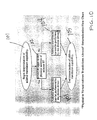
- Fig. 1 is a flow chart of a program for initializing a computer operating system program in accordance with the present invention.
- Fig. 2 is a block diagram of a portion of a computer system illustrating movement of executable computer code according to one embodiment of the present invention.
- Fig. 3 is a block diagram of a stage of memory allocation during one step of processing in accordance with one embodiment of the present invention.
- Fig. 4 is a block diagram of a state of memory allocation during a further step of processing in accordance with one embodiment of the present invention.
- Fig. 5 is a block diagram of a typical host system in which the present invention may be implemented.
- Fig. 6A is a block diagram of an initialized module for OS/2 operating system environments.
- Fig. 6B is a block diagram of the initialization module for DOS operating system environments.
- Fig. 7 is a flow chart of the initialization process according to a preferred embodiment of the present invention.
- Fig. 8 is a flow chart of one portion of the initialization code for parsing a configuration memory image in a preferred embodiment of the present invention.
- Fig. 9 is a flow chart for determining a host CPU type according to one embodiment of the present invention.
- Fig. 10 is a flow chart for determining whether physical to virtual address translation is allowed in the host data processing system according to a preferred embodiment of the present invention.
- Fig. 11 is a flow chart illustrating the relocation of code blocks according to one embodiment of the present invention.
- Fig. 12 is a diagram of a machine environment variable used for selecting code blocks according to a preferred embodiment of the present invention.
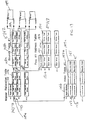
- Fig. 13 is a schematic diagram of the tables used for selecting code blocks and updating location dependent entries in code blocks according to a preferred embodiment of the present invention.
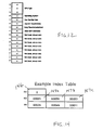
- Fig. 14 is a block diagram of an example index table according to a preferred embodiment of the present invention.
- FIG. 1-5 provide a generic description of the invention, while Figs. 6A, 6B, and 7-14 are used to illustrate a preferred embodiment.
- FIG. 1 there is shown a flow chart 10 representative of one method in accordance with the invention.
- FIG. 2 illustrates relevant portions of a computer system 12 for illustrating operation in accordance with the invention.
- Stored in mass storage 14 is for example a single executable operating system program suitable for any one of various microprocessors, such as the "86" family of microprocessors.
- Individual elements 16, 18, 20, 22 represent different encoded operating system segments forming a part of the operating system program, but each optimized for a specific microprocessor 30 (of a type yet to be identified), and program element 24 represents an encoded operating system segment which operates equally well with all of the types of microprocessor 30.
- Included is a program element 26 which is useful to identify the type of microprocessor.
- This program element 26 may be a set of instructions which executes uniquely with each of the types of microprocessors and which returns a flag of some value which identifies the type of microprocessor. It may be executable code comprising a series of tests which selectively eliminates microprocessor types as choices without resulting in an abortive attempt at execution of instructions.
- the process according to the invention starts by loading all of the program elements 16, 18, 20, 22, 24, 26 of the operating system from a mass storage system 14 into system memory 28 (Step A, Fig. 1).
- the program element 26 is then executed by the microprocessor 30 as the test for the type of the microprocessor 30 in use (Step B). With each test, a flag signal 32 is returned to the program module as a parameter for use in further execution of the program element 26 until the type of microprocessor in use is uniquely identified.
- the program element 26 identifies which portions 34 of itself are still needed and which portions 36, 38, of itself are no longer needed (Fig. 3), and the memory locations corresponding to those unneeded portions 36, 38 are released or freed for use by other programs (Step C).
- the needed portion 34 may be relocated within the memory 28 (Step D and Fig. 4). Pointers to the needed portions 34 are reset (Step E), and other portions of the operating system (if any) can be loaded (Step F). 1
- the relocated portions 16, 18, 20, or 22 may be within user-accessible memory space, or in protected memory space as portions 16', 18', 20', or 22', as shown in Fig. 4.
- the choice is typically microprocessor dependent. Control of the computer can then be turned over to other processes.
- Fig. 5 is a schematic diagram of a host computer system in which the preferred embodiment of the present invention is implemented.
- the host computer system includes a host CPU 50 which is coupled to a host bus 51.
- a host memory 52 is included connected to the host bus.
- the architecture further includes a mass storage device 53, such as a disk drive connected to the host bus 51.
- Add-on devices, such as display control 54, network interface 55, and other add-on device 56 are also coupled to the host bus 51.
- the network interface 55 in the preferred system is coupled to an Ethernet network.
- the preferred embodiment of the present invention provides a method for optimizing a device driver for the network interface 55 for an Ethernet network, according to the NDIS standard.
- Two primary goals of the present invention are to create the fastest possible code for a host variant architecture and to occupy the smallest amount of host memory. Both of these goals are met through the use of the relocatable code blocks technique outlined above.
- the technique is used for generating a driver for the NDIS industry standard network interface.
- Such a driver requires certain functional blocks in all of the host variant architectures.
- one functional block is the TransmitChain procedure.
- the initialization module several different versions of the TransmitChain procedure are stored in a TransmitChain segment. One version is written for a 286 environment, one for a 386 environment, and so on.
- the device driver determines its environment and selects the appropriate TransmitChain procedure for that environment. The selected procedure is then moved to the beginning of the TransmitChain segment. The rest of the TransmitChain procedures which were not appropriate for this environment are overwritten or discarded when the device driver returns from initialization.
- This relocatable code block technique is implemented in the preferred system in all of the performance critical device driver code. That is, all code except for code in the SupportCode segment is implemented in this technique. Thus, many different versions of the performance critical routines are written so as to provide optimal performance and minimal size for almost any host variant architecture.
- the resulting device driver after initialization, will include the following blocks of code:
- Fig. 6A for an OS/2 environment
- Fig. 6B for a DOS environment.
- the data segments including devHeaderSeg, ResDataSeg, and InitDataSeg are loaded in a data portion of host memory pointed to by a data segment selector DS.
- the functional code segments are loaded in the SupportCodeSeg, TransmitChainSeg, TransferDataSeg, ISREntrySeg, XmitCompleteSeg, ISRExitSeg, IndicationsSeg, and InitCodeSeg, and are pointed to by a code segment selector pointer CS.
- the order of the segments is somewhat different because the data and code segments are not partitioned within the memory.
- the order of segments is as follows: devHeaderSeg, ResDataSeg, SupportCodeSeg, TransmitChainSeg, ISREntrySeg, TransmitCompleteSeg, ISRExitSeg, IndicationsSeg, InitCodeSeg, InitDataSeg.
- each of the performance critical program segments is composed of at least one code block, each code block is optimized for one or more particular variant architectures, within which the device driver is intended to run.
- the initialization process for this preferred embodiment is illustrated in Fig. 7. It begins when the operating system reads the program image of the device driver from a secondary storage device and loads it into memory. The operating system then branches to the initialization code of the program, InitCodeSeg, which has been loaded into memory.
- the initialization process includes the nine steps illustrated in Fig. 7.
- the process begins by loading the program and calling the initialization code (block 70).
- the first step involves printing a message on the display terminal identifying the software which is being initialized (block 71).
- the device driver searches for an unused device driver name among all other device drivers which have been loaded (block 72).
- the protocol manager is opened to obtain a pointer to a configuration memory image, if such configuration memory exists (block 73).
- the configuration memory image is parsed to identify key words and parameters that inform the device driver of the host architecture (block 74).
- step 5 the expansion slots of the host computer are scanned for an adapter which will be controlled by this device driver. Once found, the adapter's configuration information is read (block 75).
- step 6 the variables which could not be initialized at compile time are now initialized and code is executed which determines the device driver's host environment (block 76).
- step 7 the code blocks are selected and relocated, possibly by overwriting code blocks which are not needed.
- the data structures which were initialized at compile time and in step 6 (block 76) are used to guide the relocation process.
- the host environment which was determined in steps 4 (block 74) and 6 (block 76) is also used to guide the selection and relocation process (block 77).
- step 8 the device drivers timer interrupt service routine is registered so that it will be called during each timer tick (block 78).
- step 9 the device driver informs the protocol manager that it has been initialized and is able to bind with other modules in the system (block 79). Finally, the control returns to the host operating system (block 80).
- the configuration memory image is a structure in memory created by the protocol manager in DOS or OS/2 type systems.
- the protocol manager loads before the device driver of the present invention and creates the configuration memory image.
- the key words and parameters found in the CMI help the device driver determine its environment.
- the process for parsing the configuration image is illustrated in Fig. 8.
- the algorithm begins at parsing the configuration memory image (block 81).
- step 1 the configuration memory image structure is scanned, starting with the first module. If a module is found which contains the key word DRIVERNAME, and a parameter equal to our device driver name, then we begin examining the key words of that module, starting with the first key word (block 82).
- step 2 the key word is compared against a list of valid key words. If a match is found, then the algorithm branches to step 3, otherwise, the algorithm branches to step 4 (block 83).
- step 3 a procedure is called to validate the parameters of the key word and set the environment variable according to the parameters of the key word (block 84).
- step 4 the program advances to the next key word in the CMI (block 85).
- step 5 if there are no more key words, then the routine returns to the main initialization routine, otherwise the process loops to step 2 (block 86). Finally, the routine returns to the main initialization module (block 87).
- a given host architecture may or may not include a configuration memory, or the configuration memory may not include enough information upon which the host architecture can be unambiguously identified.
- the part of the initialization process involves executing tests to determine the host environment. In the first system, two aspects of the environment are automatically determined. The CPU type of the host machine, and whether or not the device driver can perform virtual to physical address translations under the OS/2 operating system.
- First test is to determine whether the stack pointer is decremented before pushing itself onto the stack, or not (block 91). If the stack pointer is decremented before pushing, then the test is performed to determine whether a 32-position shift can be performed (block 92). If the stack pointer is not decremented before pushing, then a test is performed to determine whether the SGDT instruction stores OXFFFF in the high byte (block 93).
- the CPU is an 80386 (block 98). Otherwise, the CPU is an 80486 (block 99). Once the CPU type is determined, this algorithm is completed (block 100).
- Fig. 10 The algorithm for determining whether virtual address translations are allowed in the OS/2 environment is illustrated in Fig. 10. It begins at block 101 where a determination of address translation capability is called. This is determined by determining whether the GDTR is equal to the physical address of selector 8 at block 102. If the GDTR is equal to the physical address of selector 8, then address translations can be performed by the device driver (block 103). Otherwise, address translations cannot be performed by the device driver (block 104). This ends the determination of address translation capability (block 105).
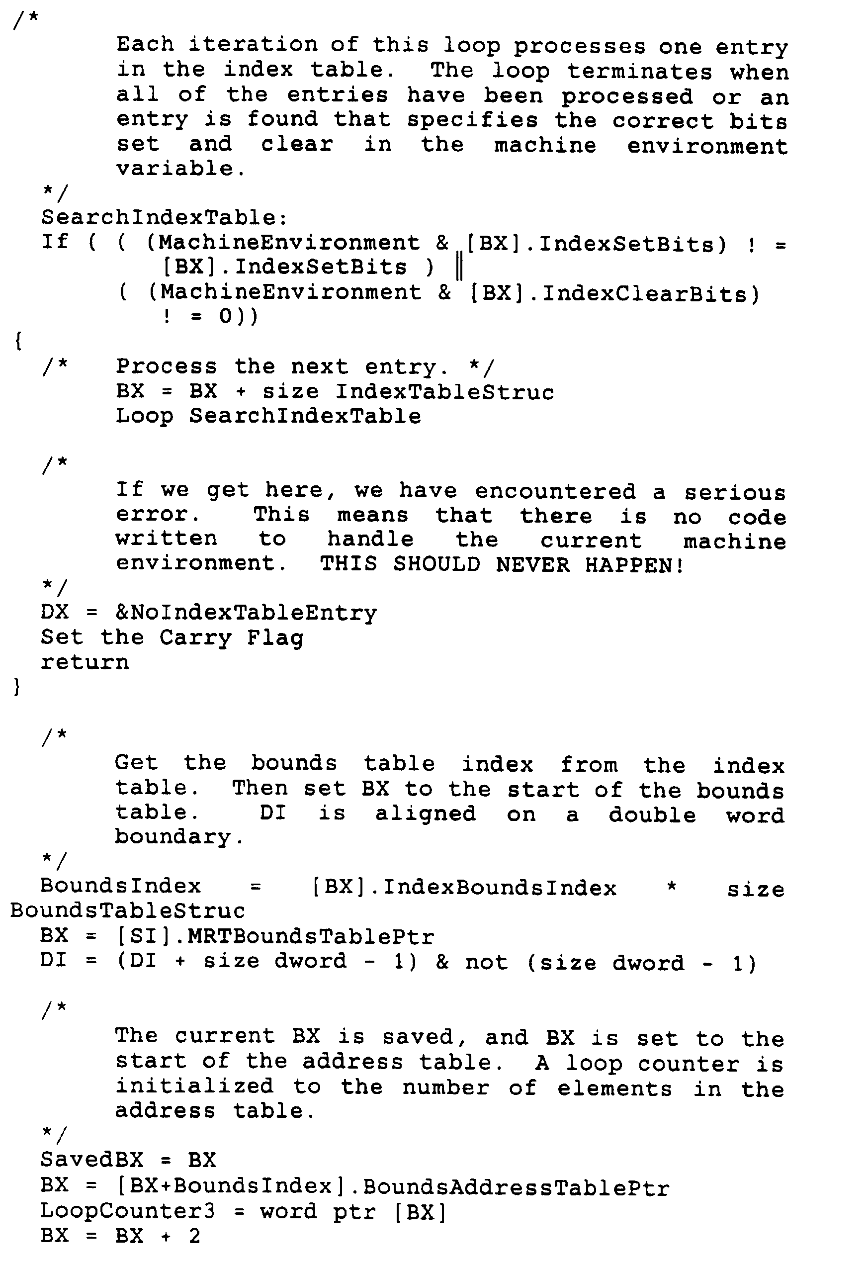
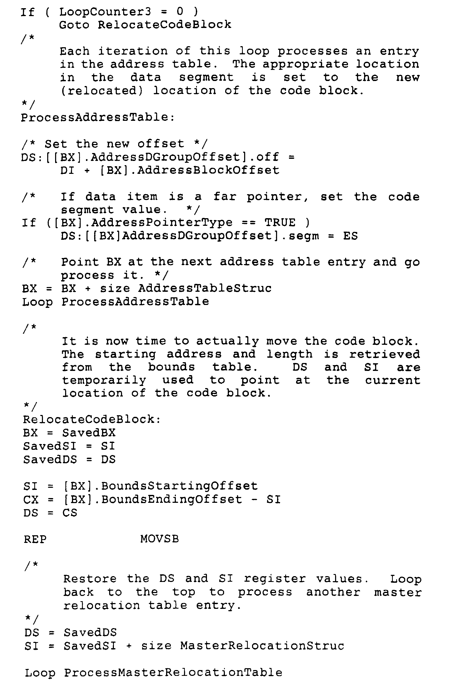
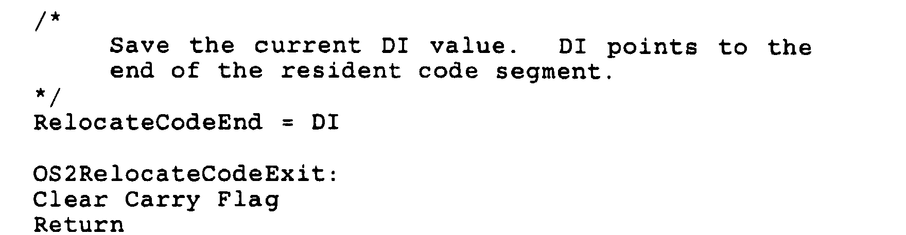
- the relocation process may begin. This process is illustrated in Fig. 11. As shown, the code relocation process begins at block 110. The first step involves setting the destination address for relocated code blocks and examining the first functional segment (block 111). Next, it is determined which procedure code block in the segment will be relocated (block 112). The procedure code block is then moved to the destination address and the destination address is set to the end of the relocated procedure code block (block 113). Next, reference is made to the next segment if there are more segments to be reviewed (block 114). If there are more code blocks, then the algorithm loops to block 112. Otherwise, the process sets up codes to free up memory beyond the current destination address (block 115), which has been set in block 113 at the end of the last relocated procedure code block. This represents the end of the relocation process (block 116).
- the relocation technique is implemented using a machine environment variable and several tables.
- the machine environment variable is illustrated in Fig. 12. It includes a bit mask that defines the host variant architecture. All of the information that is needed to select which code block will be relocated is contained in this variable. It is stored in the ResDataSegment. The variable is compiled with a value of all zeros. The fields in it are set at various points during initialization before code relocation is done and are never changed. The fields in this bit mask variable include:
- This field contains a code for the CPU in which the driver is running.
- the values for this field in the preferred system include:
- Operating system bit 3. This field contains a bit that indicates which operating system the device driver is running under. It is cleared for DOS and set for OS/2.
- bit 4 In the OS/2 environment, this bit signifies whether or not the DevHelp routines will be called in the performance critical routines. If this bit is set, the DevHelp routines will always be called. If the bit is cleared, the driver will execute code that perform the same function as the DevHelp calls which may increase performance. This bit has no meaning in the DOS environments.
- AsyncTransferData bit 5. This bit indicates whether or not an asynchronous transfer data routine is used. At this time, the asynchronous transfer data function is not a defined part of the NDIS standard for which the preferred embodiment is implemented. However, if the bit is set, the transfer data function will operate asynchronously. If it is clear, it will operate synchronously as defined in NDIS V2.0.1.
- EarlyReceiveLookAhead bit 6. This bit indicates whether or not an EarlyReceiveLookAhead function should be called in the protocol. At this time, the EarlyReceiveLookAhead function is not a defined part of the NDIS. If this bit is set, the NDIS driver will call EarlyReceiveLookAhead. If the bit is clear, ReceiveLookAhead will be called.
- the AsynchTransferData and EarlyReceiveLookAhead functions are optimizations of the NDIS driver, the implementations of which are not important to the present invention. However, their presence in the machine environment variable indicates that this variable can be used for a variety of code optimizations for a given architecture, other than those which are host CPU and operating system dependent.
- the relocation code is completely table driven. There are four types of tables illustrated in Fig. 13 which guide the relocation code through its work. These include the master relocation table 140, the index tables 141, the bounds tables 142, and the address tables 143. All of these tables are located in the InitDataSeg segment of the initialization module.
- the master relocation table 140 is the main table from which all other tables can be accessed. There is one master relocation table. Each entry in this table corresponds to one functional segment, which includes blocks to be relocated. For example, one entry in this table handles the selection and relocation of the TransmitChain procedure within the TransmitChain segment.
- the entries in the master relocation table are processed in the order that they appear in the table. Therefore, the first type of code block in the table will be the first code block relocated. The second entry in the table will be placed just after that code block, and so on. The code is relocated to the location at the beginning of the TransmitChain segment.
- the order of entries in this table must correspond to the order of segment definitions.
- the first word 144 in the master relocation table 140 contains the number of entries in the table. For the system indicated above, the number would be 6. However, it is implemented so that it can be an unsigned integer anywhere in the range from 0 to 65535.
- Each table entry e.g., 145, contains two words.
- the first word 145a is an offset to the index table for the functional segment.
- the second word 145b is an offset from the beginning of the data group to a bounds table for the functional segment. Therefore, each functional segment including blocks to be relocated, such as the TransmitChain, has associated with it an index table 141 and a bounds table 142.
- the index table 141 and the bounds table 142 allow for the correct code block to be selected and relocated based on the contents of the machine environment variable.
- the index table 141 provides a mechanism for mapping the bits of the machine environment variable into an index for the bounds table. Each entry in the master relocation table 140 points to a different index table 141.
- the index tables are located in the InitDataSeg segment.
- the mapping done by the index table allows the bounds table to be smaller than if no mapping were done.
- the index table forms an index based only on the bits in the machine environment variable which are relevant for this code block type.
- TransmitChain code blocks there may be two TransmitChain code blocks written: a 286 version and a 386/486 version.
- the relocator determines whether the processor is a 286 or a 386/486. All of the other bits in the machine environment variable can be ignored since they do not affect which code block will be selected. This mapping narrows the number of code blocks that must be selected from over 65,000 to 2. This significantly reduces the size of the bounds table.
- the first word 146 in the index table 141 contains a number of entries in the table. This is an unsigned integer that may range from 0 to 65,535. Each entry contains three words.
- the entries in the index table are processed in the order that they appear in the table, starting with the first entry 147 at offset 02.
- the first word 147a of each entry 147 is a bit mask that specifies which bits in the machine environment variable must be set in order for this entry's bounds index field to be used as an index into the bounds table.
- the second word 147b is a bit mask that specifies which bits in the machine environment variable must be clear in order for this entry's bounds index to be used as an index into the bounds table.
- the last field 147c in each index table entry 147 is a word which contains an index into the bounds table. This value is used as an index into the bounds table only if both the set and clear conditions specified in the two preceding words are met. Once an entry which meets both the setting and clear conditions is encountered by the relocator, the index into the bounds table specified by that entry is used, and the remaining index table entries are not processed.
- the index table could look as illustrated in Fig. 14.
- the first word 150 indicates that there are two entries in the table, one for each of the two versions of the TransmitChain procedure identified in the bounds table.
- the first entry in the index table causes the first entry at index 0 to be selected if bit 1 in the machine environment variable is set and bits 2 and 0 are clear. This selects the 80286 version of the TransmitChain routine. The rest of the machine environment variable bits are ignored.
- the second entry at offset 08 in this table causes the second entry in the bounds table at index 1 (0001h) to be selected if bits 1 and 0 in the machine environment variable are set and if bit 2 is clear. This selects the 80386 version of the TransmitChain routine.
- the bounds table 142 contains entries which describe a code block. Each entry in the master relocation table points to a different bounds table.
- the bounds tables are located in the InitDataSeg segment. An index into the bounds table is formed when the corresponding index table is processed as described above. The size of the bounds table, therefore, is determined by the highest value of the bounds index field of the corresponding index table.
- Each entry 148 in the bounds table 142 includes three words 148a, 148b, 148c.
- the first word 148a in each bounds table entry 148 contains an offset from the beginning of the functional segment to an address table 143.
- Each code block has associated with it an address table as described below.
- the second word 148b in the bounds table entry 148 is an offset from the beginning of the functional segment code group to the start of the code block 149.
- the third word 148c in the entry 148 of the bounds table is an offset from the beginning of the functional segment code group to the first byte beyond the end of the code block 149.
- the second and third words provide the bounds of the code block. This information is used when moving the code block into lower memory during a relocation process.
- the address table 143 contains a list of location dependent entries in the resident data segment that must be modified so that they refer to the appropriate locations in a relocated code block. For example, the entry in the MAC upper dispatch table that contains the address of the TransmitChain routine must be updated to point to the new location of the relocated TransmitChain. Every code block has associated with it an address table. These tables are located in the InitDataSeg segment.
- the first word 150 in the address table contains a number of entries in the table. This is an unsigned integer that may range from 0 to 65,535.
- the address table entries follow this word.
- Each address table entry 151 includes three words 151a, 151b, 151c.
- the first word 151a in each address table entry 151 contains an offset from the beginning of the code block. The entry at this offset is pointed to by a variable in a data segment. For example, if the TransmitChain procedure entry point is at offset la hex in the code block (as distinguished from the functional segment code group), then la hex will be placed in the first word 151a of the entry 151.
- the second word 151b in each address table entry 151 contains an offset in the functional segment code group to a pointer that points to this code block.
- the memory location pointed to by this word will be set to the value found by adding the starting location of the relocating code block plus the offset given in the first word 151a of the address table entry 151.
- the third word 151c in each address table entry 151 contains a flag which specifies whether or not the pointer in the functional segment code group is a near or far pointer. If this word is set true, then a far pointer is assumed to be at that location, and the code segment value will be written along with the offset. If this word is false, then the near pointer is assumed to be at that location, and only the offset is written.
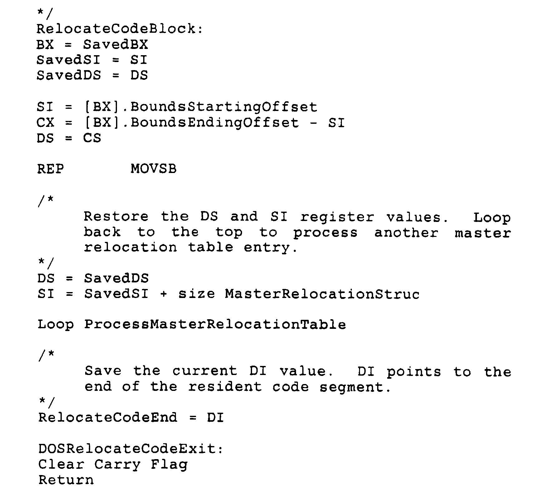
- This routine is called from the DOSdevInitInterrupt routine.
- the MachineEnvironment variable and all of the relocation tables guide this code through the relocation process.
- An outer loop iterates through all of the entries in the master relocation table. Each entry in the index table for the current master relocation table entry is examined in an inner loop. Once an entry is found that matches the configuration of the MachineEnvironment variable the inner loop is terminated and the corresponding entry in the bounds table is processed.
- the first field which contains the offset to an address table, is used. Each entry in the address table is examined and the appropriate address in the data segment is "fixed-up”. The second and third fields in the bounds table are then used to relocate the code block into the new code segment. After the code block has been relocated the next entry in the master relocation table is processed.
- This routine is called from the OS2devInitStrategy routine.
- the MachineEnvironment variable and all of the relocation tables guide this code through the relocation process.
- An outer loop iterates through all of the entries in the master relocation table. Each entry in the index table for the current master relocation table entry is examined in an inner loop. Once an entry is found that matches the configuration of the MachineEnvironment variable the inner loop is terminated and the corresponding entry in the bounds table is processed.
- the first field which contains the offset to an address table is used. Each entry in the address table is examined and the appropriate address in the data segment is "fixed-up”. The second and third fields in the bounds table are then used to relocate the code block into the new code segment. After the code block has been relocated the next entry in the master relocation table is processed.
- the performance critical code is the code which is used to transmit and receive packets. This includes the TransmitChain, TransferData, the XmitComplete and RcvComplete paths in the interrupt service routine, and the IndicationOn/IndicationOff procedures. These procedures are described below in summary fashion as examples for implementing the invention.
- This routine initiates the transmission of a packet. It is called by the protocol whenever the protocol wants to transmit a packet.
- the code in this routine is specifically optimized for the DOS 80286 environment. This routine copies the request handle, protocol id, immediate data count, data block count, immediate data, and the data block descriptors to the adapter.
- This routine initiates the transmission of a packet. It is called by the protocol whenever the protocol wants to transmit a packet.
- the code in this routine is specifically optimized for the DOS 80386/80486 environment. This routine copies the request handle, protocol id, immediate data count, data block count, immediate data, and the data block descriptors to the adapter.
- This routine copies a received packet to protocol managed buffers.
- the code in this routine is specifically optimized for the DOS 80286 environment.
- the number of transfer data blocks, the frame offset, and the transfer data block descriptors are written to the adapter.
- the transfer is then initiated by reading the XferQueueStatus register and the driver polls until the transfer is complete. When the transfer is complete the status of the transfer is returned to the protocol.
- This routine copies a received packet to protocol managed buffers.
- the code in this routine has been specifically optimized for the DOS 80386/80486 environment.
- the number of transfer data blocks, the frame offset, and the transfer data block descriptors are written to the adapter.
- the transfer is then initiated by reading the XferQueueStatus register and the driver polls until the transfer is complete. When the transfer is complete the status of the transfer is returned to the protocol.
- This routine disables indications.
- the adapter handles the indication counter and the disabling of indications. This routine simply writes to the IndicationOff register in the adapter controller.
- This routine contains the vector interrupt entry point for the adapter interrupt.
- the code in this routine is specifically optimized for the DOS 80286 environment.
- the ISREntry code handles the "housekeeping" chores that need to be taken care of before the indication(s) that caused the interrupt can be handled.
- This routine first checks to see if our adapter generated the interrupt or if we need to chain to another interrupt service routine. Then all of the registers are saved on the stack and we switch stacks to our own private interrupt stack. All adapter interrupts are disabled and system interrupts are re-enabled.
- This routine also contains the code to handle a received packet indication. Because this indication is the most common type of indication it is handled as fall-through code. The other indications are handled by branching through a dispatch table. If a received packet caused the indication, the RcvFrameStatus is polled to verify that the packet has been completely received. The LengthLeftThresh register is then modified, if necessary, and ReceiveLookAhead is called. The LookAhead window is then advanced.
- a dispatch table is used to branch to the next indication that needs to be handled. If no more indications need to be handled, the dispatch table branches to the code which exits from the interrupt service routine.
- This routine contains the vector interrupt entry point for the adapter interrupt.
- the code in this routine is specifically optimized for the DOS 80386/80486 environment.
- the ISREntry code handles the "housekeeping" chores that need to be taken care of before the indication(s) that caused the interrupt can be handled.
- This routine first checks to see if our adapter generated the interrupt or if we need to chain to another interrupt service routine. Then all of the registers are saved on the stack and we switch stacks to our own private interrupt stack. All adapter interrupts are disabled and system interrupts are re-enabled.
- This routine also contains the code to handle a received packet indication. Because this indication is the most common type of indication it is handled as fall-through code. The other indications are handled by branching through a dispatch table. If a received packet caused the indication the RcvFrameStatus is polled to verify that the packet has been completely received. The LengthLeftThresh register is then modified, if necessary, and ReceiveLookAhead is called. The SlapStick LookAhead window is then advanced.
- a dispatch table is used to branch to the next indication that needs to be handled. If no more indications need to be handled, the dispatch table branches to the code which exits from the interrupt service routine.
- This routine is called through the PrimaryIntDispatch or SecondaryIntDispatch table when an XmitComplete indication occurs. This code is specifically optimized for the DOS 80286 environment. This routine adjusts the XmitCompleteThresh register, if necessary, and calls the protocol's transmit confirm procedure.
- a dispatch table is used to branch to the next indication that needs to be handled. If no more indications need to be handled, the dispatch table branches to the code which exits from the interrupt service routine.
- This routine is called through the PrimaryIntDispatch or SecondaryIntDispatch table when an XmitComplete indication occurs. This code is specifically optimized for the DOS 80386/80486 environment. This routine adjusts the XmitCompleteThresh register, if necessary, and calls the protocol's transmit confirm procedure.
- a dispatch table is used to branch to the next indication that needs to be handled. If no more indications need to be handled, the dispatch table branches to the code which exits from the interrupt service routine.
- This routine is branched to through the PrimaryIntDispatch or the SecondaryIntDispatch table. This routine is optimized for the DOS 80286 environment. The purpose of this routine is to call indication complete, if necessary, and return from the interrupt context.
- This routine is branched to through the PrimaryIntDispatch or the SecondaryIntDispatch table. This routine has been optimized for the DOS 80386/80486 environment. The purpose of this routine is to call indication complete, if necessary, and return from the interrupt context.
- This routine is called from the other indication handlers through the PrimaryIntDispatch or the SecondaryIntDispatch table.
- the purpose of this routine is to handle an OtherIndication indication (bit 5 in the IndicationComplete register).
- the OtherIndication may be caused by one of three events.
- This routine calls the StartReset and Endreset status indications, and performs the actual reset of the adapter and the MAC driver.
- the third reason this indication may be generated is when the transmitter encounters a DMA underrun error. This is caused when the adapter is transmitting a packet on the network faster than the bus master can load the packet data onto the adapter. In this case, the XmitStartThresh register is increased to allow more data to be resident on the adapter before a transmit begins.
- This routine initiates the transmission of a packet. It is called by the protocol whenever the protocol wants to transmit a packet.
- the code in this routine is specifically optimized for the OS/2 80286 environment when GDT addresses are not allowed for data buffer descriptors.
- This routine copies the request handle, protocol id, immediate data count, data block count, immediate data, and the data block descriptors to the adapter.
- This routine initiates the transmission of a packet. It is called by the protocol whenever the protocol wants to transmit a packet.
- the code in this routine is specifically optimized for the OS/2 80386/80486 environment when GDT addresses are not allowed for data buffer descriptors.
- This routine copies the request handle, protocol id, immediate data count, data block count, immediate data, and the data block descriptors to the adapter.
- This routine initiates the transmission of a packet. It is called by the protocol whenever the protocol wants to transmit a packet.
- the code in this routine is specifically optimized for the OS/2 80286 environment when GDT addresses are allowed for data buffer descriptors.
- This routine copies the request handle, protocol id, immediate data count, data block count, immediate data, and the data block descriptors to the adapter.
- This routine initiates the transmission of a packet. It is called by the protocol whenever the protocol wants to transmit a packet.
- the code in this routine is specifically optimized for the OS/2 80386/80486 environment when GDT addresses are allowed for data buffer descriptors.
- This routine copies the request handle, protocol id, immediate data count, data block count,immediate data, and the data block descriptors to the adapter.
- This routine copies a received packet to protocol managed buffers.
- the code in this routine has been specifically optimized for the OS/2 80286 environment when GDT selectors are not allowed in data buffer descriptors.
- the number of transfer data blocks, the frame offset, and the transfer data block descriptors are written to the adapter.
- the transfer is then initiated by reading the XferQueueStatus register and the driver polls until the transfer is complete. When the transfer is complete the status of the transfer is returned to the protocol.
- This routine copies a received packet to protocol managed buffers.
- the code in this routine has been specifically optimized for the OS/2 80386/80486 environment when GDT selectors are not allowed in data buffer descriptors.
- the number of transfer data blocks, the frame offset, and the transfer data block descriptors are written to the adapter.
- the transfer is then initiated by reading the XferQueueStatus register and the driver polls until the transfer is complete. When the transfer is complete the status of the transfer is returned to the protocol.
- This routine copies a received packet to protocol managed buffers.
- the code in this routine is specifically optimized for the OS/2 80286 environment when GDT selectors are allowed in data buffer descriptors.
- the number of transfer data blocks, the frame offset, and the transfer data block descriptors are written to the adapter.
- the transfer is then initiated by reading the XferQueueStatus register and the driver polls until the transfer is complete. When the transfer is complete the status of the transfer is returned to the protocol.
- This routine copies a received packet to protocol managed buffers.
- the code in this routine is specifically optimized for the OS/2 80386/80486 environment when GDT selectors not allowed in data buffer descriptors.
- the number of transfer data blocks, the frame offset, and the transfer data block descriptors are written to the adapter.
- the transfer is then initiated by reading the XferQueueStatus register and the driver polls until the transfer is complete. When the transfer is complete the status of the transfer is returned to the protocol.
- This routine disables indications.
- the adapter handles the indication counter and the disabling of indications. This routine simply writes to the IndicationOff register of the adapter controller.
- This routine contains the interrupt entry point for the adapter interrupt.
- the code in this routine is specifically optimized for the OS/2 80286 environment when devHelp calls should be avoided.
- the ISREntry code handles the "housekeeping" chores that need to be taken care of before the indication(s) that caused the interrupt can be handled.
- This routine first checks to see if our adapter generated the interrupt or if we need to chain to another interrupt service routine. All adapter interrupts are disabled and system interrupts are re-enabled.
- This routine also contains the code to handle a received packet indication. Because this indication is the most common type of indication it is handled as fall-through code. The other indications are handled by branching through a dispatch table. If a received packet caused the indication the RcvFrameStatus is polled to verify that the packet has been completely received. The LengthLeftThresh register is then modified, if necessary, and ReceiveLookAhead is called. The LookAhead window is then advanced.
- a dispatch table is used to branch to the next indication that needs to be handled. If no more indications need to be handled, the dispatch table branches to the code which exists from the interrupt service routine.
- This routine contains the interrupt entry point for the adapter interrupt.
- the code in this routine is specifically optimized for the OS/2 80386/80486 environment when devHelp calls should be avoided.
- the ISREntry code handles the "housekeeping" chores that need to be taken care of before the indication(s) that caused the interrupt can be handled. This routine first checks to see if our adapter generated the interrupt or if we need to chain to another interrupt service routine. All adapter interrupts are disabled and system interrupts are re-enabled.
- This routine also contains the code to handle a received packet indication. Because this indication is the most common type of indication it is handled as fall-through code. The other indications are handled by branching through a dispatch table. If a received packet caused the indication the RcvFrameStatus is polled to verify that the packet has been completely received. The LengthLeftThresh register is then modified, if necessary, and ReceiveLookAhead is called. The LookAhead window is then advanced.
- a dispatch table is used to branch to the next indication that needs to be handled. If no more indications need to be handled, the dispatch table branches to the code which exits from the interrupt service routine.
- This routine contains the interrupt entry point for the adapter interrupt.
- the code in this routine has been specifically optimized for the OS/2 80286 environment when devHelp calls should always be called.
- the ISREntry code handles the "housekeeping" chores that need to be taken care of before the indication(s) that caused the interrupt can be handled.
- This routine first checks to see if our adapter generated the interrupt or if we need to chain to another interrupt service routine. All adapter interrupts are disabled and system interrupts are re-enabled.
- This routine also contains the code to handle a received packet indication. Because this indication is the most common type of indication it is handled as fall-through code. The other indications are handled by branching through a dispatch table. If a received packet caused the indication the RcvFrameStatus is polled to verify that the packet has been completely received. The LengthLeftThresh register is then modified, if necessary, and ReceiveLookAhead is called. The LookAhead window is then advanced.
- a dispatch table is used to branch to the next indication that needs to be handled. If no more indications need to be handled, the dispatch table branches to the code which exits from the interrupt service routine.
- This routine contains the interrupt entry point for the SlapStick adapter interrupt.
- the code in this routine is specifically optimized for the OS/2 80386/486 environment when devHelp calls should always be called.
- the ISREntry code handles the "housekeeping" chores that need to be taken care of before the indication(s) that caused the interrupt can be handled. This routine first checks to see if our adapter generated the interrupt or if we need to chain to another interrupt service routine. All adapter interrupts are disabled and system interrupt are re-enabled.
- This routine also contains the code to handle a received packet indication. Because this indication is the most common type of indication it is handled as fall-through code. The other indications are handled by branching through a dispatch table. If a received packet caused the indication the RcvFrameStatus is polled to verify that the packet has been completely received. The LengthLeftThresh register is the modified, if necessary, and ReceiveLookAhead is called. The SlapStick LookAhead window is then advanced.
- a dispatch table is used to branch to the next indication that needs to be handled. If no more indications need to be handled, the dispatch table branches to the code which exits from the interrupt service routine.
- This routine is called through the PrimaryIntDispatch or SecondaryIntDispatch table when an XmitComplete indication occurs. This code is specifically optimized for the OS/2 80286 environment. This routine adjusts the XmitCompleteThresh register, if necessary, and calls the protocol's transmit confirm procedure.
- a dispatch table is used to branch to the next indication that needs to be handled. If no more indications need to be handled, the dispatch table branches to the code which exits from the interrupt service routine.
- This routine is called through the PrimaryIntDispatch or SecondaryIntDispatch table when an XmitComplete indication occurs. This code has been specifically optimized for the OS/2 80386/80486 environment. This routine adjusts the XmitCompleteThresh register, if necessary, and calls the protocol's transmit confirm procedure.
- a dispatch table is used to branch to the next indication that needs to be handled. If no more indications need to be handled, the dispatch table branches to the code which exits from the interrupt service routine.
- This routine is branched to through the PrimaryIntDispatch or the SecondaryIntDispatch table. This routine is optimized for the OS/2 80286 environment. The purpose of this routine is to call indication complete, if necessary, and return from the interrupt context.
- This routine is branched to through the PrimaryIntDispatch or the SecondaryIntDispatch table.
- This routine has been optimized for the OS/2 80386/80486 environment. The purpose of this routine is to call indication complete, if necessary, and return from the interrupt context.
- This routine is called from the other indication handlers through the PrimaryIntDispatch or the SecondaryIntDispatch table.
- the purpose of this routine is to handle an OtherIndication indication (bit 5 in the IndicationComplete register).
- the OtherIndication indication may be caused by one of three events.
- This routine calls the StartReset and EndReset status indications, and performs the actual reset of the adapter and the MAC driver.
- the third reason this indication may be generated is when the transmitter encounters a DMA underrun error. This is caused when the adapter is transmitting a packet on the network faster than the bus master can load the packet data onto the adapter. In this case, the XmitStartThresh register is increased to allow more data to be resident on the adapter before a transmit begins.
- a self-contained, executable module of an operating system normally stored in mass memory for use in any one of a plurality of variant host architectures is provided which is first loaded into user memory space of the central processing unit, and then executed to optimize the module for any one of the plurality of host variant architectures. It involves sensing the type of central processing unit in use, relocating a portion of the loaded executable file into an optimized segment of user accessible memory space, which may include overwriting other portions of the memory space occupied by the executable module itself, redirecting all the vectors and interrupts in accordance with the type of CPU in use and the relocated code block, and discarding all surplus segments of the executable code in the loaded module to free the memory for use by other applications programs, and/or operating system modules.
- the invention may be implemented either in the form of an executable file or it may be implemented in the form of a device driver.
- the relocated segment of the executable code module may overwrite memory locations of other portions of the same executable code or, alternatively, the segment of code may be relocated into a protected memory space as defined in connection with the central processing unit and/or operating system, in order to free up a maximum amount of user accessible memory space for other programs.
- the invention is particularly useful in systems such as device drivers for network interfaces, which must remain resident in host memory throughout active processing which involves the network. These systems occupy a portion of a host memory, and limit the use of host memory for other applications. It is necessary that such code be optimized for speed and space as taught by the present invention.
Landscapes
- Engineering & Computer Science (AREA)
- Theoretical Computer Science (AREA)
- Software Systems (AREA)
- Physics & Mathematics (AREA)
- General Engineering & Computer Science (AREA)
- General Physics & Mathematics (AREA)
- Stored Programmes (AREA)
Abstract
Description
- Segment:
- InitCodeseg
- Inputs:
- DS points to the data segment.
MachineEnvironment. All of the bits which affect code relocation must be initialized.
Relocation Tables. The relocation tables must contain the proper values to guide this procedure. - Outputs:
- Carry flag. If carry is set, then an
error occurred. Otherwise, no error.
DX. If an error occurred, DX
contains the offset to the error
message.
The code segment is modified.
RelocateCodeEnd. This variable is set to the offset from the beginning of the device driver to the byte beyond the last byte of code that was relocated. - Interrupt State:
- Unchanged.


- Segment:
- InitCodeSeg
- Inputs:
- DS points to the data segment.
MachineEnvironment. All of the bits which affect code relocation must be initialized.
Relocation Tables. The relocation tables must contain the proper values to guide this procedure. - Outputs:
- Carry flag. If carry is set, then an
error occurred. Otherwise, no error.
DX. If an error occurred, DX contains the offset to the error message.
The code segment is modified.
RelocateCodeEnd. This variable is set to the offset from the beginning of the device driver to the byte beyond the last byte of code that was relocated. - Interrupt State:
- Unchanged.


286
386
286
386
286 and 386
286
386
286
386
286
386
- Segment:
- TransmitChainSeg
- Inputs:
- SS:SP+6 - Our data segment value.
SS:SP+8 - Pointer to a transmit frame buffer descriptor.
SS:SP+12 - Request handle.
SS:SP+14 - Protocol ID.
XmitAreaPtr - This variable contains a far pointer to the
Area register for the adapter controller. - Outputs:
- AX contains an NDIS return code.
- Interrupt State:
- Disabled in entry and enabled on exit.
- Segment:
- TransmitChainSeg
- Inputs:
- SS:SP+6 - Our data segment value.
SS:SP+8 - Pointer to a transmit frame buffer descriptor.
SS:SP+12 - Request handle.
SS:SP+14 - Protocol ID.
AdapterSegment - This variable contains the segment selector of the Adapter RAM. - Outputs:
- AX contains an NDIS return code.
- Interrupt State:
- Disabled in entry and enabled on exit.
- Segment:
- TransferDataSeg
- Inputs:
- SS:SP+6 - Our data segment value.
SS:SP+8 - Far pointer to a transfer data descriptor.
SS:SP+12 - Starting offset in frame for transfer.
SS:SP+14 - Far pointer to a word that contains the number of bytes copied. AdapterSegment - Contains the Adapter's RAM segment selector. - Outputs:
- AX contains an NDIS return code.
- Interrupt State:
- Unchanged.
- Segment:
- TransferDataSeg
- Inputs:
- SS:SP+6 - Our data segment value.
SS:SP+8 - Far pointer to a transfer data descriptor.
SS:SP+12 - Starting offset in frame for transfer.
SS:SP+14 - Far pointer to a word that contains the number of bytes copied.
AdapterSegment - Contains the Adapter's RAM segment selector. - Outputs:
- AX contains an NDIS return code.
- Interrupt State:
- Unchanged.
- Segment:
- IndicationsSeg
- Inputs:
- SS:SP+6 - Our data segment value.
- Outputs:
- AX contains an NDIS return code (always SUCCESS).
- Interrupt State:
- Cleared upon entry and not re-enabled.
- Segment:
- IndicationsSeg
- Inputs:
- SS:SP+6 - Our data segment value.
- Outputs:
- AX contains an NDIS return code (always SUCCESS).
- Interrupt State:
- Cleared upon entry and not re-enabled.
- Segment:
- ISREntrySeg
- Inputs:
- None.
- Outputs:
- DS is set to the Adapter's RAM segment selector.
- Interrupt State:
- Disabled on entry and enabled on exit.
- Segment:
- ISREntrySeg
- Inputs:
- None.
- Outputs:
- DS is set to the Adapter's RAM segment selector.
- Interrupt State:
- Disabled on entry and enabled on exit.
- Segment:
- XmitCompleteSeg
- Inputs:
- DS is set to the Adapter's RAM segment selector.
- Outputs:
- None.
- Interrupt State:
- Unknown on entry and unchanged.
- Segment:
- XmitCompleteSeg
- Inputs:
- DS is set to the Adapter's RAM segment selector.
- Outputs:
- None.
- Interrupt State:
- Unknown on entry and unchanged.
- Segment:
- ISRExitSeg
- Inputs:
- DS contains the adapter's RAM segment selector.
- Outputs:
- None.
- Interrupt State:
- Cleared on entry, enabled if IndicationComplete is called, enabled when the IRET instruction is executed.
- Segment:
- ISRExitSeg
- Inputs:
- DS contains the adapter's RAM segment selector.
- Outputs:
- None.
- Interrupt State:
- Cleared on entry, enabled if IndicationComplete is called, enabled when the IRET instruction is executed.
- Segment:
- SupportCodeSeg
- Inputs:
- DS contains the adapter's RAM segment selector.
- Outputs:
- None.
- Interrupt State:
- Unknown on entry and may be enabled.
286 and 386 version
- Segment:
- TransmitChainSeg
- Inputs:
- SS:SP+6 - Our data segment value.
SS:SP+8 - Pointer to a transmit frame buffer descriptor.
SS:SP+12 - Request handle.
SS:SP+14 - Protocol ID.
XmitAreaPtr - This variable contains a far pointer to the
XmitArea register. - Outputs:
- AX contains an NDIS return code.
- Interrupt State:
- Disabled in entry and enabled on exit.
- Segment:
- TransmitChainSeg
- Inputs:
- SS:SP+6 - Our data segment value.
SS:SP+8 - Pointer to a transmit frame buffer descriptor.
SS:SP+12 - Request handle.
SS:SP+14 - Protocol ID.
SegmentSelector - This variable contains the segment selector of the Adapter RAM. - Outputs:
- AX contains an NDIS return code.
- Interrupt State:
- Disabled in entry and enabled on exit.
- Segment:
- TransmitChainSeg
- Inputs:
- SS:SP+6 - Our data segment value.
SS:SP+8 - Pointer to a transmit frame buffer descriptor.
SS:SP+12 - Request handle.
SS:SP+14 - Protocol ID.
XmitAreaPtr - This variable contains a far pointer to the XmitArea register. - Outputs:
- AX contains an NDIS return code.
- Interrupt State:
- Disabled in entry and enabled on exit.
This routine copies the request handle, protocol id, immediate data count, data block count,immediate data, and the data block descriptors to the adapter.
- Segment:
- TransmitChainSeg
- Inputs:
- SS:SP+6 - Our data segment value.
SS:SP+8 - Pointer to a transmit frame buffer descriptor.
SS:SP+12 - Request handle.
SS:SP+14 - Protocol ID.
SegmentSelector - This variable contains the segment selector of the Adapter RAM. - Outputs:
- AX contains an NDIS return code.
- Interrupt State:
- Disabled in entry and enabled on exit.
- Segment:
- TransferDataSeg
- Inputs:
- SS:SP+6 - Our data segment value.
SS:SP+8 - Far pointer to a transfer data descriptor.
SS:SP+12 - Starting offset in frame for transfer.
SS:SP+14 - Far pointer to a word that contains the number of bytes copied.
SegmentSelector - Contains the Adapter's RAM segment selector. - Outputs:
- AX contains an NDIS return code.
- Interrupt State:
- Unchanged.
- Segment:
- TransferDataSeg
- Inputs:
- SS:SP+6 - Our data segment value.
SS:SP+8 - Far pointer to a transfer data descriptor.
SS:SP+12 - Starting offset in frame for transfer.
SS:SP+14 - Far pointer to a word that contains the number of bytes copied.
SegmentSelector - Contains the Adapter's RAM segment selector. - Outputs:
- AX contains an NDIS return code.
- Interrupt State:
- Unchanged.
- Segment:
- TransferDataSeg
- Inputs:
- SS:SP+6 - Our data segment value.
SS:SP+8 - Far pointer to a transfer data descriptor.
SS:SP+12 - Starting offset in frame for transfer.
SS:SP+14 - Far pointer to a word that contains the number of bytes copied. SegmentSelector - Contains the Adapter's RAM segment selector. - Outputs:
- AX contains and NDIS return code.
- Interrupt State:
- Unchanged.
- Segment:
- TransferDataSeg
- Inputs:
- SS:SP+6 - Our data segment value.
SS:SP+8 - Far pointer to a transfer data descriptor.
SS:SP+12 - Starting offset in frame for transfer.
SS:SP+14 - Far pointer to a word that contains the number of bytes copied. SegmentSelector - Contains the Adapter's RAM segment selector. - Outputs:
- AX contains an NDIS return code.
- Interrupt State:
- Unchanged.
- Segment:
- IndicationSeg
- Inputs:
- SS:SP+6 - Our data segment value.
SegmentSelector - Contains the adapter's RAM segment selector. - Outputs:
- AX contains an NDIS return code (always SUCCESS).
- Interrupt State:
- Cleared upon entry and not re-enabled.
- Segment:
- IndicationsSeg
- Inputs:
- SS:SP+6 - Our data segment value.
SegmentSelector - Contains the adapter's RAM segment selector. - Outputs:
- AX contains an NDIS return code (always SUCCESS).
- Interrupt State:
- Cleared upon entry and not re-enabled.
- Segment:
- ISREntrySeg
- Inputs:
- DS is set to the driver's data segment selector.
- Outputs:
- ES is set to the Adapter's RAM segment selector.
- Interrupt State:
- Disabled on entry and enabled on exit.
- Segment:
- ISREntrySeg
- Inputs:
- DS is set to the driver's data segment selector.
- Outputs:
- ES is set to the Adapters RAM segment selector.
- Interrupt State:
- Disabled on entry and enabled on exit.
- Segment:
- ISREntrySeg
- Inputs:
- DS is set to the driver's data segment selector.
- Outputs:
- ES is set to the Adapter's RAM segment selector.
- Interrupt State:
- Disabled on entry and enabled on exit.
- Segment:
- ISREntrySeg
- Inputs:
- DS is set to the driver's data segment selector.
- Outputs:
- ES is set to the Adapter's RAM segment selector.
- Interrupt State:
- Disabled on entry and enabled on exit.
- Segment:
- XmitCompleteSeg
- Inputs:
- ES is set to the Adapter's RAM segment selector.
- Outputs:
- None.
- Interrupt State:
- Unknown on entry and unchanged.
- Segment:
- XmitCompleteSeg
- Inputs:
- ES is set to the Adapter's RAM segment selector.
- Outputs:
- None.
- Interrupt State:
- Unknown on entry and unchanged.
- Segment:
- ISRExitSeg
- Inputs:
- ES contains the adapter's RAM segment selector.
- Outputs:
- None.
- Interrupt State:
- Cleared on entry, enabled if IndicationComplete is called, enabled when the IRET instruction is executed.
- Segment:
- ISRExitSeg
- Inputs:
- ES contains the adapter's RAM segment selector.
- Outputs:
- None.
- Interrupt State:
- Cleared on entry, enabled if IndicationComplete is called, enabled when the IRET instruction is executed.
- Segment:
- SupportCodeSeg
- Inputs:
- ES contains the adapter's RAm segment selector.
- Outputs:
- None.
- Interrupt State:
- Unknown on entry and may be enabled.
Claims (20)
- A method for initializing software in a host data processing system (12), the host having any one of a plurality of variant architectures, comprising:loading into host memory (28) a software module including a set of code blocks (16,18,20,22), each code block adapted for at least one of the plurality of variant architectures;identifying the variant architecture of the host;selecting a subset of the set of code blocks adapted for the identified variant architecture;locating the subset within the host memory (28) in contiguous memory locations; andfreeing memory locations of the software module in host memory (28) outside the contiguous memory locations.
- The method of claim 1, wherein at least one of the plurality of variant architectures includes a configuration table storing variables identifying attributes of the host architecture, and the step of identifying includes:
parsing (74) the configuration table. - The method of claim 1, wherein the step of identifying includes: executing tests to determine features of the host architecture.
- The method of claim 1, wherein host architecture includes a limited address space and the subset of the software module occupies host memory (28) during execution of other software.
- A method according to claim 1 in which said software is operating system software for controlling an add-on device (56) and said software module is an initialize module in which the code blocks are operating system code blocks for the add-on device.
- The method of claim 5, wherein host architecture includes a limited address space and the subset of code blocks for the add-on device occupies host memory during execution of applications software.
- The method of claim 1 or 5, wherein the set of code blocks in the software module comprises a plurality of functional segments, each functional segment in the plurality including at least one code block, and the step of selecting a subset includes:
selecting a code block from each functional segment in the plurality of functional segments. - The method of claim 1 or 5, wherein the software module further includes tables for identifying locations of code blocks, and location dependent entries within code blocks, based on the identified variant architecture; and the step of selecting includes:accessing the tables in response to the identified variant architecture to identify selected code blocks: andthe step of locating includes accessing selected code blocks and updating location-dependent entries in selected code blocks.
- A method according to claim 1 in which said software is operating system software for controlling an add-on device (56) and the host has limited host memory, wherein:said software module is an initialize module in which said set of code blocks comprises a plurality of functional segments, each functional segment in the plurality including at least one code block for the add-on device (56), the initialize module further including an environment variable, and tables for identifying a code block in each functional segment in response to the environment variable;said step of identifying the variant architecture of the host further includes updating the environment variable to indicate the identified variant architecture; andsaid step of selecting comprises accessing the tables in response to the updated environment variable to select a code block adapted for the indicated variant architecture from each of the plurality of functional segments.
- The method of claim 9, wherein the tables in the initialize module identify location-dependent entries within the selected code blocks; and the step of locating includes:
accessing selected code blocks and updating location-dependent entries in selected code blocks. - The method of claim 1, 5 or 9, wherein the step of loading includes storing the software module in a memory space beginning at a first address and ending at a second address; andthe contiguous memory locations begin at the first address and end at a third address: andthe step of freeing includes freeing memory locations between the third and second addresses.
- The method of claim 5 or 9, wherein at least one of the plurality of variant architectures includes a configuration table storing variables identifying attributes of the host architecture, and the initialize module includes an architecture variable, and the step of identifying includes:parsing the configuration table; andupdating the architecture variable in response to entries in the configuration table.
- The method of claim 5 or 9, wherein the initialize module includes an environment variable, and the step of identifying includes:executing tests to determine features of the host architecture: andupdating the environment variable in response to results of the tests.
- The method of claim 5 or 9, wherein the add-on device comprises a network interface, and the operating system software for the network interface includes code for transmitting and receiving data through the network interface.
- A method for automatically optimizing usage of a microprocessor unit (30) in a computer system (12) which also comprises user-accessible memory (28), said method comprising the steps of:loading an executable version of a computer operating system program into the memory (28), said executable version having executable code for uniquely identifying each one of a selected variety of microprocessing units (30);executing said operating system program to sense type of microprocessor unit in service in said computer system to return a flag signal (32) identifying microprocessor type;freeing locations of said memory (28) containing first portions of said operating system program not needed by said microprocessor type (30) in accordance with said flag signal (32); andrelocating second portions of said operating system program within said memory (28) to improve memory space usage based on decisions following said flag signal.
- The method according to claim 15 wherein said relocating step includes relocating said second portions over and in place of said first portions.
- The method according to claim 16 wherein said relocating step includes resetting vectors to operate with the second portions as relocated.
- The method according to claim 15 wherein said relocating step includes resetting vectors to operate with the second portions as relocated.
- The method according to claim 15 wherein said relocating step comprises relocating selected code segments outside of user-accessible memory space (28) of the microprocessor unit (30) and resetting vectors and interrupts to operate with needed second portions of said operating system program as relocated.
- The method according to claim 15 wherein said operating system program is loaded as a device driver.
Applications Claiming Priority (3)
| Application Number | Priority Date | Filing Date | Title |
|---|---|---|---|
| US53325790A | 1990-06-04 | 1990-06-04 | |
| US533257 | 1990-06-04 | ||
| PCT/US1991/003870 WO1991019244A1 (en) | 1990-06-04 | 1991-06-03 | Method for optimizing software for any one of a plurality of variant architectures |
Publications (3)
| Publication Number | Publication Date |
|---|---|
| EP0532643A1 EP0532643A1 (en) | 1993-03-24 |
| EP0532643A4 EP0532643A4 (en) | 1993-09-15 |
| EP0532643B1 true EP0532643B1 (en) | 1998-12-23 |
Family
ID=24125174
Family Applications (1)
| Application Number | Title | Priority Date | Filing Date |
|---|---|---|---|
| EP91911416A Expired - Lifetime EP0532643B1 (en) | 1990-06-04 | 1991-06-03 | Method for optimizing software for any one of a plurality of variant architectures |
Country Status (4)
| Country | Link |
|---|---|
| US (2) | US5459854A (en) |
| EP (1) | EP0532643B1 (en) |
| DE (1) | DE69130673T2 (en) |
| WO (1) | WO1991019244A1 (en) |
Cited By (1)
| Publication number | Priority date | Publication date | Assignee | Title |
|---|---|---|---|---|
| DE10234063A1 (en) * | 2002-07-26 | 2004-02-19 | Audi Ag | Version specific programming of program and data memory in a motor vehicle control unit, whereby version data and program alterations are stored with the base program and a particular version is selected using a selection tool |
Families Citing this family (57)
| Publication number | Priority date | Publication date | Assignee | Title |
|---|---|---|---|---|
| US5809300A (en) * | 1992-03-16 | 1998-09-15 | Fujitsu Limited | Removable storage medium and computer system using the same |
| GB2268293A (en) * | 1992-06-17 | 1994-01-05 | Texas Instruments Ltd | Installing a resident part of a Terminate and Stay Resident program. |
| US5790834A (en) * | 1992-08-31 | 1998-08-04 | Intel Corporation | Apparatus and method using an ID instruction to identify a computer microprocessor |
| US6357000B1 (en) * | 1993-01-29 | 2002-03-12 | Microsoft Corporation | Method and system for specified loading of an operating system |
| US6430685B1 (en) * | 1993-02-19 | 2002-08-06 | Apple Computer, Inc. | Method and apparatus for enabling a computer system |
| EP0621535B1 (en) * | 1993-04-23 | 2000-03-15 | Advanced Micro Devices, Inc. | Interrupt handling |
| US5432937A (en) * | 1993-08-20 | 1995-07-11 | Next Computer, Inc. | Method and apparatus for architecture independent executable files |
| JP3251414B2 (en) * | 1994-01-11 | 2002-01-28 | 三菱電機株式会社 | Programmable controller and method for changing program capacity thereof |
| US5668992A (en) * | 1994-08-01 | 1997-09-16 | International Business Machines Corporation | Self-configuring computer system |
| JPH08286893A (en) * | 1995-03-15 | 1996-11-01 | Eastman Kodak Co | Computer file for execution of plurality vendors and plurality of architectures and its formation method |
| US5765198A (en) * | 1996-02-01 | 1998-06-09 | Cray Research, Inc. | Transparent relocation of real memory addresses in the main memory of a data processor |
| US6308325B1 (en) * | 1996-04-09 | 2001-10-23 | International Business Machines Corporation | Apparatus and method for downloading data to electronic device |
| US5875318A (en) * | 1996-04-12 | 1999-02-23 | International Business Machines Corporation | Apparatus and method of minimizing performance degradation of an instruction set translator due to self-modifying code |
| US5794049A (en) * | 1996-06-05 | 1998-08-11 | Sun Microsystems, Inc. | Computer system and method for executing architecture specific code with reduced run-time memory space requirements |
| JP3052857B2 (en) * | 1996-10-31 | 2000-06-19 | 日本電気株式会社 | Inter-cluster shared memory access method |
| US5835775A (en) * | 1996-12-12 | 1998-11-10 | Ncr Corporation | Method and apparatus for executing a family generic processor specific application |
| GB2321981B (en) * | 1997-02-06 | 2002-01-09 | Ibm | Hosted machine code installation |
| US6128730A (en) * | 1997-12-29 | 2000-10-03 | Bull Hn Information Systems Inc. | Method and apparatus for multilevel software configuration having administrator and software driven override limiting capabilities |
| US6189009B1 (en) * | 1999-08-27 | 2001-02-13 | The Voice.Com, Inc. | System and method for integrating paper-based business documents with computer-readable data entered via a computer network |
| JP2003528368A (en) * | 1999-08-27 | 2003-09-24 | コンフィデックス、コーポレーション | System and method for integrating paper-based business documents with computer readable data entered via a computer network |
| US20010007146A1 (en) * | 1999-12-23 | 2001-07-05 | Uwe Hansmann | Method for providing a set of software components |
| US6588008B1 (en) * | 2000-04-11 | 2003-07-01 | International Business Machines Corporation | Assembler tool for processor-coprocessor computer systems |
| US6968317B1 (en) * | 2000-04-28 | 2005-11-22 | Charles Schwab & Co., Inc. | Method and apparatus for new accounts program |
| US7107587B1 (en) * | 2000-09-18 | 2006-09-12 | Microsoft Corporation | Access redirector and entry reflector |
| FI113898B (en) * | 2000-11-21 | 2004-06-30 | Nokia Corp | Process for producing content in a wireless communication device |
| US7085815B2 (en) * | 2001-07-17 | 2006-08-01 | International Business Machines Corporation | Scalable memory management of token state for distributed lock managers |
| US7159214B2 (en) | 2001-07-26 | 2007-01-02 | Kyocera Wireless Corp. | System and method for compacting field upgradeable wireless communication device software code sections |
| US7197302B2 (en) * | 2001-07-26 | 2007-03-27 | Kyocera Wireless Corp. | System and method for interchangeable modular hardware components for wireless communication devices |
| US7027806B2 (en) * | 2001-07-26 | 2006-04-11 | Kyocera Wireless, Corp. | System and method for field downloading a wireless communications device software code section |
| US7184759B2 (en) * | 2001-07-26 | 2007-02-27 | Kyocera Wireless Corp. | Modular software components for wireless communication devices |
| US7386846B2 (en) * | 2001-07-26 | 2008-06-10 | Kyocera Wireless Corp. | System and method for the management of wireless communications device system software downloads in the field |
| US7184793B2 (en) * | 2001-07-26 | 2007-02-27 | Kyocera Wireless Corp. | System and method for over the air area code update |
| US9554268B2 (en) * | 2001-07-26 | 2017-01-24 | Kyocera Corporation | System and method for updating persistent data in a wireless communications device |
| US7328007B2 (en) * | 2001-07-26 | 2008-02-05 | Kyocera Wireless Corp. | System and method for organizing wireless communication device system software |
| US7143407B2 (en) * | 2001-07-26 | 2006-11-28 | Kyocera Wireless Corp. | System and method for executing wireless communications device dynamic instruction sets |
| US7200389B2 (en) * | 2001-07-26 | 2007-04-03 | Kyocera Wireless Corp. | Dynamic interface software for wireless communication devices |
| US7254386B2 (en) * | 2001-08-10 | 2007-08-07 | Kyocera Wireless Corp. | System and method for improved security in handset reprovisioning and reprogramming |
| US6961537B2 (en) * | 2001-08-10 | 2005-11-01 | Kyocera Wireless Corp. | System and method for peer-to-peer handset communication |
| US7117494B2 (en) * | 2001-08-10 | 2006-10-03 | Kyocera Wireless Corp. | System and method for bi-directional communication and execution of dynamic instruction sets |
| US7322028B2 (en) * | 2001-09-19 | 2008-01-22 | Belovich Steven G | Method and system for providing a virus-immune, rule-based cross-platform software system |
| US20090106353A1 (en) * | 2001-09-19 | 2009-04-23 | Belovich Steven G | Method and system for providing an event auditing client server software arrangement |
| SE521753C2 (en) * | 2002-02-08 | 2003-12-02 | Xelerated Ab | Procedures and systems for meeting real-time requirements for a data processor |
| US7003656B2 (en) * | 2002-06-13 | 2006-02-21 | Hewlett-Packard Development Company, L.P. | Automatic selection of firmware for a computer that allows a plurality of process types |
| US6996708B1 (en) * | 2002-09-30 | 2006-02-07 | Ncr Corporation | Methods and apparatus for automatically selecting and loading initialization software for a hardware configuration |
| EP1473630A3 (en) * | 2003-04-11 | 2007-10-10 | Samsung Electronics Co., Ltd. | Computer system and method of setting an interface card therein |
| GB2402764B (en) * | 2003-06-13 | 2006-02-22 | Advanced Risc Mach Ltd | Instruction encoding within a data processing apparatus having multiple instruction sets |
| US7266677B1 (en) * | 2003-09-25 | 2007-09-04 | Rockwell Automation Technologies, Inc. | Application modifier based on operating environment parameters |
| GB2406662A (en) * | 2003-09-30 | 2005-04-06 | Toshiba Res Europ Ltd | Configuring a computer apparatus |
| US7249238B2 (en) | 2004-06-15 | 2007-07-24 | International Business Machines Corporation | Memory tracking with preservation of alignment semantics |
| US8578332B2 (en) * | 2007-04-30 | 2013-11-05 | Mark Murray | Universal microcode image |
| US8230412B2 (en) * | 2007-08-31 | 2012-07-24 | Apple Inc. | Compatible trust in a computing device |
| GB2460462A (en) * | 2008-05-30 | 2009-12-02 | Symbian Software Ltd | Method for loading software components into RAM by modifying the software part to be loaded based on the memory location to be used. |
| FR2945135B1 (en) * | 2009-04-29 | 2011-04-22 | Continental Automotive France | METHOD FOR OPTIMIZING THE STORAGE OF CALIBRATION DATA IN A AUTOMOTIVE ELECTRONIC COMPUTER |
| US8407322B1 (en) * | 2010-08-24 | 2013-03-26 | Adobe Systems Incorporated | Runtime negotiation of execution blocks between computers |
| WO2015171918A2 (en) | 2014-05-07 | 2015-11-12 | Louisiana State University And Agricultural And Mechanical College | Compositions and uses for treatment thereof |
| WO2016094837A2 (en) | 2014-12-11 | 2016-06-16 | Igenica Biotherapeutics, Inc. | Anti-c10orf54 antibodies and uses thereof |
| TWI773646B (en) | 2015-06-08 | 2022-08-11 | 美商宏觀基因股份有限公司 | Lag-3-binding molecules and methods of use thereof |
Family Cites Families (20)
| Publication number | Priority date | Publication date | Assignee | Title |
|---|---|---|---|---|
| UST912006I4 (en) * | 1972-07-31 | 1973-07-10 | Multiphase nucleus loading for a virtual storage system | |
| US3828325A (en) * | 1973-02-05 | 1974-08-06 | Honeywell Inf Systems | Universal interface system using a controller to adapt to any connecting peripheral device |
| US4435752A (en) * | 1973-11-07 | 1984-03-06 | Texas Instruments Incorporated | Allocation of rotating memory device storage locations |
| GB1601955A (en) * | 1977-10-21 | 1981-11-04 | Marconi Co Ltd | Data processing systems |
| US4200915A (en) * | 1978-04-05 | 1980-04-29 | Allen-Bradley Company | Program loader for programmable controller |
| JPS6037938B2 (en) * | 1980-12-29 | 1985-08-29 | 富士通株式会社 | information processing equipment |
| US4654783A (en) * | 1982-07-26 | 1987-03-31 | Data General Corporation | Unique process for loading a microcode control store in a data processing system |
| JPS5947645A (en) * | 1982-09-13 | 1984-03-17 | Toshiba Corp | Program loading system |
| US4589063A (en) * | 1983-08-04 | 1986-05-13 | Fortune Systems Corporation | Data processing system having automatic configuration |
| AU575182B2 (en) * | 1984-06-28 | 1988-07-21 | Wang Laboratories, Inc. | Self extending memory file |
| US4701848A (en) * | 1984-11-19 | 1987-10-20 | Clyde, Inc. | System for effectively paralleling computer terminal devices |
| US4779189A (en) * | 1985-06-28 | 1988-10-18 | International Business Machines Corporation | Peripheral subsystem initialization method and apparatus |
| JPS6226535A (en) * | 1985-07-22 | 1987-02-04 | インタ−ナショナル ビジネス マシ−ンズ コ−ポレ−ション | Correction of conversion table in program |
| JPH06103460B2 (en) * | 1985-11-19 | 1994-12-14 | ソニー株式会社 | Program transfer method |
| US4768150A (en) * | 1986-09-17 | 1988-08-30 | International Business Machines Corporation | Application program interface to networking functions |
| FR2606566B1 (en) * | 1986-09-22 | 1993-04-30 | Nec Corp | INITIALIZATION METHOD FOR A CHANNEL CONTROLLER |
| US4926322A (en) * | 1987-08-03 | 1990-05-15 | Compag Computer Corporation | Software emulation of bank-switched memory using a virtual DOS monitor and paged memory management |
| US4961133A (en) * | 1987-11-06 | 1990-10-02 | Visystems, Inc. | Method for providing a virtual execution environment on a target computer using a virtual software machine |
| JP2753706B2 (en) * | 1987-12-09 | 1998-05-20 | 富士通株式会社 | IPL method in computer |
| US4970639A (en) * | 1988-05-20 | 1990-11-13 | International Business Machines Corporation | Virtual machine architecture independent program loader |
-
1991
- 1991-06-03 EP EP91911416A patent/EP0532643B1/en not_active Expired - Lifetime
- 1991-06-03 DE DE69130673T patent/DE69130673T2/en not_active Expired - Fee Related
- 1991-06-03 WO PCT/US1991/003870 patent/WO1991019244A1/en not_active Ceased
- 1991-07-09 US US07/727,824 patent/US5459854A/en not_active Expired - Lifetime
-
1995
- 1995-04-06 US US08/417,840 patent/US5600823A/en not_active Expired - Lifetime
Cited By (2)
| Publication number | Priority date | Publication date | Assignee | Title |
|---|---|---|---|---|
| DE10234063A1 (en) * | 2002-07-26 | 2004-02-19 | Audi Ag | Version specific programming of program and data memory in a motor vehicle control unit, whereby version data and program alterations are stored with the base program and a particular version is selected using a selection tool |
| DE10234063B4 (en) * | 2002-07-26 | 2004-09-30 | Audi Ag | Method for variant-specific programming of a program and data memory of a control device, in particular a control device of a motor vehicle, and device for carrying out the method |
Also Published As
| Publication number | Publication date |
|---|---|
| US5600823A (en) | 1997-02-04 |
| DE69130673D1 (en) | 1999-02-04 |
| EP0532643A4 (en) | 1993-09-15 |
| EP0532643A1 (en) | 1993-03-24 |
| DE69130673T2 (en) | 1999-05-20 |
| US5459854A (en) | 1995-10-17 |
| WO1991019244A1 (en) | 1991-12-12 |
Similar Documents
| Publication | Publication Date | Title |
|---|---|---|
| US5459854A (en) | Method for optimizing software for any one of a plurality of variant architectures | |
| US5655146A (en) | Coexecution processor isolation using an isolation process or having authority controls for accessing system main storage | |
| US5638517A (en) | Method and apparatus for transmitting a message from a computer system over a network adapter to the network by performing format conversion and memory verification | |
| US5715387A (en) | Method and system for loading and confirming correct operation of an application program in a target system | |
| US6711605B2 (en) | Multi OS configuration method and computer system | |
| JP3705547B2 (en) | Apparatus for executing a plurality of program segments having various object code types in one program or one processor environment | |
| US5594903A (en) | Operating System architecture with reserved memory space resident program code identified in file system name space | |
| US4442484A (en) | Microprocessor memory management and protection mechanism | |
| EP0187603B1 (en) | Computer with virtual machine mode and multiple protection rings | |
| US7213247B1 (en) | Protection domains for a computer operating system | |
| US5634046A (en) | General purpose use of a stack pointer register | |
| US5740464A (en) | Architecture for providing input/output operations in a computer system | |
| US6631515B1 (en) | Method and apparatus to reduce code size and runtime in a Java environment | |
| US6356996B1 (en) | Cache fencing for interpretive environments | |
| US5701483A (en) | Data acess implementation of device driver interface | |
| US5257381A (en) | Method of intercepting a global function of a network operating system and calling a monitoring function | |
| US5638535A (en) | Method and apparatus for providing flow control with lying for input/output operations in a computer system | |
| US20030056071A1 (en) | Adaptable boot loader | |
| US6148321A (en) | Processor event recognition | |
| US20030115584A1 (en) | Method and system to instrument virtual function calls | |
| WO1998019238A1 (en) | Heterogeneous symmetric multi-processing system | |
| US5918050A (en) | Apparatus accessed at a physical I/O address for address and data translation and for context switching of I/O devices in response to commands from application programs | |
| US20040167996A1 (en) | Computer system having a virtualized I/O device | |
| US5603014A (en) | Protected mode simulation of a real mode interupt based programming interface in a computer system | |
| US20040221131A1 (en) | Virtual memory translation control by TLB purge monitoring |
Legal Events
| Date | Code | Title | Description |
|---|---|---|---|
| PUAI | Public reference made under article 153(3) epc to a published international application that has entered the european phase |
Free format text: ORIGINAL CODE: 0009012 |
|
| 17P | Request for examination filed |
Effective date: 19921221 |
|
| AK | Designated contracting states |
Kind code of ref document: A1 Designated state(s): DE FR GB IT |
|
| A4 | Supplementary search report drawn up and despatched |
Effective date: 19930727 |
|
| AK | Designated contracting states |
Kind code of ref document: A4 Designated state(s): DE FR GB IT |
|
| 17Q | First examination report despatched |
Effective date: 19960425 |
|
| GRAG | Despatch of communication of intention to grant |
Free format text: ORIGINAL CODE: EPIDOS AGRA |
|
| GRAG | Despatch of communication of intention to grant |
Free format text: ORIGINAL CODE: EPIDOS AGRA |
|
| GRAH | Despatch of communication of intention to grant a patent |
Free format text: ORIGINAL CODE: EPIDOS IGRA |
|
| GRAH | Despatch of communication of intention to grant a patent |
Free format text: ORIGINAL CODE: EPIDOS IGRA |
|
| GRAA | (expected) grant |
Free format text: ORIGINAL CODE: 0009210 |
|
| AK | Designated contracting states |
Kind code of ref document: B1 Designated state(s): DE FR GB IT |
|
| REF | Corresponds to: |
Ref document number: 69130673 Country of ref document: DE Date of ref document: 19990204 |
|
| ET | Fr: translation filed | ||
| PLBE | No opposition filed within time limit |
Free format text: ORIGINAL CODE: 0009261 |
|
| STAA | Information on the status of an ep patent application or granted ep patent |
Free format text: STATUS: NO OPPOSITION FILED WITHIN TIME LIMIT |
|
| 26N | No opposition filed | ||
| PGFP | Annual fee paid to national office [announced via postgrant information from national office to epo] |
Ref country code: FR Payment date: 20010517 Year of fee payment: 11 |
|
| PGFP | Annual fee paid to national office [announced via postgrant information from national office to epo] |
Ref country code: GB Payment date: 20010521 Year of fee payment: 11 |
|
| PGFP | Annual fee paid to national office [announced via postgrant information from national office to epo] |
Ref country code: DE Payment date: 20010523 Year of fee payment: 11 |
|
| REG | Reference to a national code |
Ref country code: GB Ref legal event code: IF02 |
|
| PG25 | Lapsed in a contracting state [announced via postgrant information from national office to epo] |
Ref country code: GB Free format text: LAPSE BECAUSE OF NON-PAYMENT OF DUE FEES Effective date: 20020603 |
|
| PG25 | Lapsed in a contracting state [announced via postgrant information from national office to epo] |
Ref country code: DE Free format text: LAPSE BECAUSE OF NON-PAYMENT OF DUE FEES Effective date: 20030101 |
|
| GBPC | Gb: european patent ceased through non-payment of renewal fee |
Effective date: 20020603 |
|
| PG25 | Lapsed in a contracting state [announced via postgrant information from national office to epo] |
Ref country code: FR Free format text: LAPSE BECAUSE OF NON-PAYMENT OF DUE FEES Effective date: 20030228 |
|
| REG | Reference to a national code |
Ref country code: FR Ref legal event code: ST |
|
| PGFP | Annual fee paid to national office [announced via postgrant information from national office to epo] |
Ref country code: IT Payment date: 20060630 Year of fee payment: 16 |
|
| PG25 | Lapsed in a contracting state [announced via postgrant information from national office to epo] |
Ref country code: IT Free format text: LAPSE BECAUSE OF NON-PAYMENT OF DUE FEES Effective date: 20070603 |