EP0531246A1 - A braking device for self-closing doors - Google Patents
A braking device for self-closing doors Download PDFInfo
- Publication number
- EP0531246A1 EP0531246A1 EP92610061A EP92610061A EP0531246A1 EP 0531246 A1 EP0531246 A1 EP 0531246A1 EP 92610061 A EP92610061 A EP 92610061A EP 92610061 A EP92610061 A EP 92610061A EP 0531246 A1 EP0531246 A1 EP 0531246A1
- Authority
- EP
- European Patent Office
- Prior art keywords
- braking device
- plumb
- drop
- door
- eddy
- Prior art date
- Legal status (The legal status is an assumption and is not a legal conclusion. Google has not performed a legal analysis and makes no representation as to the accuracy of the status listed.)
- Granted
Links
Images

Classifications
-
- E—FIXED CONSTRUCTIONS
- E05—LOCKS; KEYS; WINDOW OR DOOR FITTINGS; SAFES
- E05F—DEVICES FOR MOVING WINGS INTO OPEN OR CLOSED POSITION; CHECKS FOR WINGS; WING FITTINGS NOT OTHERWISE PROVIDED FOR, CONCERNED WITH THE FUNCTIONING OF THE WING
- E05F1/00—Closers or openers for wings, not otherwise provided for in this subclass
- E05F1/02—Closers or openers for wings, not otherwise provided for in this subclass gravity-actuated, e.g. by use of counterweights
- E05F1/025—Closers or openers for wings, not otherwise provided for in this subclass gravity-actuated, e.g. by use of counterweights with rectilinearly-moving counterweights
-
- E—FIXED CONSTRUCTIONS
- E05—LOCKS; KEYS; WINDOW OR DOOR FITTINGS; SAFES
- E05F—DEVICES FOR MOVING WINGS INTO OPEN OR CLOSED POSITION; CHECKS FOR WINGS; WING FITTINGS NOT OTHERWISE PROVIDED FOR, CONCERNED WITH THE FUNCTIONING OF THE WING
- E05F1/00—Closers or openers for wings, not otherwise provided for in this subclass
- E05F1/002—Closers or openers for wings, not otherwise provided for in this subclass controlled by automatically acting means
- E05F1/006—Closers or openers for wings, not otherwise provided for in this subclass controlled by automatically acting means by emergency conditions, e.g. fire
-
- E—FIXED CONSTRUCTIONS
- E05—LOCKS; KEYS; WINDOW OR DOOR FITTINGS; SAFES
- E05F—DEVICES FOR MOVING WINGS INTO OPEN OR CLOSED POSITION; CHECKS FOR WINGS; WING FITTINGS NOT OTHERWISE PROVIDED FOR, CONCERNED WITH THE FUNCTIONING OF THE WING
- E05F5/00—Braking devices, e.g. checks; Stops; Buffers
- E05F5/003—Braking devices, e.g. checks; Stops; Buffers for sliding wings
-
- E—FIXED CONSTRUCTIONS
- E05—LOCKS; KEYS; WINDOW OR DOOR FITTINGS; SAFES
- E05D—HINGES OR SUSPENSION DEVICES FOR DOORS, WINDOWS OR WINGS
- E05D13/00—Accessories for sliding or lifting wings, e.g. pulleys, safety catches
- E05D13/10—Counterbalance devices
- E05D13/14—Counterbalance devices with weights
-
- E—FIXED CONSTRUCTIONS
- E05—LOCKS; KEYS; WINDOW OR DOOR FITTINGS; SAFES
- E05Y—INDEXING SCHEME ASSOCIATED WITH SUBCLASSES E05D AND E05F, RELATING TO CONSTRUCTION ELEMENTS, ELECTRIC CONTROL, POWER SUPPLY, POWER SIGNAL OR TRANSMISSION, USER INTERFACES, MOUNTING OR COUPLING, DETAILS, ACCESSORIES, AUXILIARY OPERATIONS NOT OTHERWISE PROVIDED FOR, APPLICATION THEREOF
- E05Y2201/00—Constructional elements; Accessories therefor
- E05Y2201/20—Brakes; Disengaging means; Holders; Stops; Valves; Accessories therefor
- E05Y2201/21—Brakes
-
- E—FIXED CONSTRUCTIONS
- E05—LOCKS; KEYS; WINDOW OR DOOR FITTINGS; SAFES
- E05Y—INDEXING SCHEME ASSOCIATED WITH SUBCLASSES E05D AND E05F, RELATING TO CONSTRUCTION ELEMENTS, ELECTRIC CONTROL, POWER SUPPLY, POWER SIGNAL OR TRANSMISSION, USER INTERFACES, MOUNTING OR COUPLING, DETAILS, ACCESSORIES, AUXILIARY OPERATIONS NOT OTHERWISE PROVIDED FOR, APPLICATION THEREOF
- E05Y2201/00—Constructional elements; Accessories therefor
- E05Y2201/20—Brakes; Disengaging means; Holders; Stops; Valves; Accessories therefor
- E05Y2201/218—Holders
-
- E—FIXED CONSTRUCTIONS
- E05—LOCKS; KEYS; WINDOW OR DOOR FITTINGS; SAFES
- E05Y—INDEXING SCHEME ASSOCIATED WITH SUBCLASSES E05D AND E05F, RELATING TO CONSTRUCTION ELEMENTS, ELECTRIC CONTROL, POWER SUPPLY, POWER SIGNAL OR TRANSMISSION, USER INTERFACES, MOUNTING OR COUPLING, DETAILS, ACCESSORIES, AUXILIARY OPERATIONS NOT OTHERWISE PROVIDED FOR, APPLICATION THEREOF
- E05Y2201/00—Constructional elements; Accessories therefor
- E05Y2201/20—Brakes; Disengaging means; Holders; Stops; Valves; Accessories therefor
- E05Y2201/218—Holders
- E05Y2201/22—Locks
-
- E—FIXED CONSTRUCTIONS
- E05—LOCKS; KEYS; WINDOW OR DOOR FITTINGS; SAFES
- E05Y—INDEXING SCHEME ASSOCIATED WITH SUBCLASSES E05D AND E05F, RELATING TO CONSTRUCTION ELEMENTS, ELECTRIC CONTROL, POWER SUPPLY, POWER SIGNAL OR TRANSMISSION, USER INTERFACES, MOUNTING OR COUPLING, DETAILS, ACCESSORIES, AUXILIARY OPERATIONS NOT OTHERWISE PROVIDED FOR, APPLICATION THEREOF
- E05Y2201/00—Constructional elements; Accessories therefor
- E05Y2201/20—Brakes; Disengaging means; Holders; Stops; Valves; Accessories therefor
- E05Y2201/23—Actuation thereof
- E05Y2201/232—Actuation thereof by automatically acting means
- E05Y2201/234—Actuation thereof by automatically acting means direction dependent
-
- E—FIXED CONSTRUCTIONS
- E05—LOCKS; KEYS; WINDOW OR DOOR FITTINGS; SAFES
- E05Y—INDEXING SCHEME ASSOCIATED WITH SUBCLASSES E05D AND E05F, RELATING TO CONSTRUCTION ELEMENTS, ELECTRIC CONTROL, POWER SUPPLY, POWER SIGNAL OR TRANSMISSION, USER INTERFACES, MOUNTING OR COUPLING, DETAILS, ACCESSORIES, AUXILIARY OPERATIONS NOT OTHERWISE PROVIDED FOR, APPLICATION THEREOF
- E05Y2201/00—Constructional elements; Accessories therefor
- E05Y2201/20—Brakes; Disengaging means; Holders; Stops; Valves; Accessories therefor
- E05Y2201/23—Actuation thereof
- E05Y2201/246—Actuation thereof by auxiliary motors, magnets, springs or weights
-
- E—FIXED CONSTRUCTIONS
- E05—LOCKS; KEYS; WINDOW OR DOOR FITTINGS; SAFES
- E05Y—INDEXING SCHEME ASSOCIATED WITH SUBCLASSES E05D AND E05F, RELATING TO CONSTRUCTION ELEMENTS, ELECTRIC CONTROL, POWER SUPPLY, POWER SIGNAL OR TRANSMISSION, USER INTERFACES, MOUNTING OR COUPLING, DETAILS, ACCESSORIES, AUXILIARY OPERATIONS NOT OTHERWISE PROVIDED FOR, APPLICATION THEREOF
- E05Y2201/00—Constructional elements; Accessories therefor
- E05Y2201/20—Brakes; Disengaging means; Holders; Stops; Valves; Accessories therefor
- E05Y2201/252—Type of friction
- E05Y2201/258—Magnetic or electromagnetic friction
-
- E—FIXED CONSTRUCTIONS
- E05—LOCKS; KEYS; WINDOW OR DOOR FITTINGS; SAFES
- E05Y—INDEXING SCHEME ASSOCIATED WITH SUBCLASSES E05D AND E05F, RELATING TO CONSTRUCTION ELEMENTS, ELECTRIC CONTROL, POWER SUPPLY, POWER SIGNAL OR TRANSMISSION, USER INTERFACES, MOUNTING OR COUPLING, DETAILS, ACCESSORIES, AUXILIARY OPERATIONS NOT OTHERWISE PROVIDED FOR, APPLICATION THEREOF
- E05Y2201/00—Constructional elements; Accessories therefor
- E05Y2201/20—Brakes; Disengaging means; Holders; Stops; Valves; Accessories therefor
- E05Y2201/262—Type of motion, e.g. braking
- E05Y2201/266—Type of motion, e.g. braking rotary
-
- E—FIXED CONSTRUCTIONS
- E05—LOCKS; KEYS; WINDOW OR DOOR FITTINGS; SAFES
- E05Y—INDEXING SCHEME ASSOCIATED WITH SUBCLASSES E05D AND E05F, RELATING TO CONSTRUCTION ELEMENTS, ELECTRIC CONTROL, POWER SUPPLY, POWER SIGNAL OR TRANSMISSION, USER INTERFACES, MOUNTING OR COUPLING, DETAILS, ACCESSORIES, AUXILIARY OPERATIONS NOT OTHERWISE PROVIDED FOR, APPLICATION THEREOF
- E05Y2201/00—Constructional elements; Accessories therefor
- E05Y2201/40—Motors; Magnets; Springs; Weights; Accessories therefor
- E05Y2201/404—Function thereof
- E05Y2201/41—Function thereof for closing
-
- E—FIXED CONSTRUCTIONS
- E05—LOCKS; KEYS; WINDOW OR DOOR FITTINGS; SAFES
- E05Y—INDEXING SCHEME ASSOCIATED WITH SUBCLASSES E05D AND E05F, RELATING TO CONSTRUCTION ELEMENTS, ELECTRIC CONTROL, POWER SUPPLY, POWER SIGNAL OR TRANSMISSION, USER INTERFACES, MOUNTING OR COUPLING, DETAILS, ACCESSORIES, AUXILIARY OPERATIONS NOT OTHERWISE PROVIDED FOR, APPLICATION THEREOF
- E05Y2201/00—Constructional elements; Accessories therefor
- E05Y2201/40—Motors; Magnets; Springs; Weights; Accessories therefor
- E05Y2201/46—Magnets
- E05Y2201/462—Electromagnets
-
- E—FIXED CONSTRUCTIONS
- E05—LOCKS; KEYS; WINDOW OR DOOR FITTINGS; SAFES
- E05Y—INDEXING SCHEME ASSOCIATED WITH SUBCLASSES E05D AND E05F, RELATING TO CONSTRUCTION ELEMENTS, ELECTRIC CONTROL, POWER SUPPLY, POWER SIGNAL OR TRANSMISSION, USER INTERFACES, MOUNTING OR COUPLING, DETAILS, ACCESSORIES, AUXILIARY OPERATIONS NOT OTHERWISE PROVIDED FOR, APPLICATION THEREOF
- E05Y2201/00—Constructional elements; Accessories therefor
- E05Y2201/40—Motors; Magnets; Springs; Weights; Accessories therefor
- E05Y2201/50—Weights
-
- E—FIXED CONSTRUCTIONS
- E05—LOCKS; KEYS; WINDOW OR DOOR FITTINGS; SAFES
- E05Y—INDEXING SCHEME ASSOCIATED WITH SUBCLASSES E05D AND E05F, RELATING TO CONSTRUCTION ELEMENTS, ELECTRIC CONTROL, POWER SUPPLY, POWER SIGNAL OR TRANSMISSION, USER INTERFACES, MOUNTING OR COUPLING, DETAILS, ACCESSORIES, AUXILIARY OPERATIONS NOT OTHERWISE PROVIDED FOR, APPLICATION THEREOF
- E05Y2201/00—Constructional elements; Accessories therefor
- E05Y2201/60—Suspension or transmission members; Accessories therefor
- E05Y2201/622—Suspension or transmission members elements
- E05Y2201/658—Members cooperating with flexible elongated pulling elements
- E05Y2201/668—Pulleys; Wheels
-
- E—FIXED CONSTRUCTIONS
- E05—LOCKS; KEYS; WINDOW OR DOOR FITTINGS; SAFES
- E05Y—INDEXING SCHEME ASSOCIATED WITH SUBCLASSES E05D AND E05F, RELATING TO CONSTRUCTION ELEMENTS, ELECTRIC CONTROL, POWER SUPPLY, POWER SIGNAL OR TRANSMISSION, USER INTERFACES, MOUNTING OR COUPLING, DETAILS, ACCESSORIES, AUXILIARY OPERATIONS NOT OTHERWISE PROVIDED FOR, APPLICATION THEREOF
- E05Y2400/00—Electronic control; Electrical power; Power supply; Power or signal transmission; User interfaces
- E05Y2400/10—Electronic control
- E05Y2400/30—Electronic control of motors
- E05Y2400/3013—Electronic control of motors during manual wing operation
-
- E—FIXED CONSTRUCTIONS
- E05—LOCKS; KEYS; WINDOW OR DOOR FITTINGS; SAFES
- E05Y—INDEXING SCHEME ASSOCIATED WITH SUBCLASSES E05D AND E05F, RELATING TO CONSTRUCTION ELEMENTS, ELECTRIC CONTROL, POWER SUPPLY, POWER SIGNAL OR TRANSMISSION, USER INTERFACES, MOUNTING OR COUPLING, DETAILS, ACCESSORIES, AUXILIARY OPERATIONS NOT OTHERWISE PROVIDED FOR, APPLICATION THEREOF
- E05Y2800/00—Details, accessories and auxiliary operations not otherwise provided for
- E05Y2800/25—Emergency conditions
-
- E—FIXED CONSTRUCTIONS
- E05—LOCKS; KEYS; WINDOW OR DOOR FITTINGS; SAFES
- E05Y—INDEXING SCHEME ASSOCIATED WITH SUBCLASSES E05D AND E05F, RELATING TO CONSTRUCTION ELEMENTS, ELECTRIC CONTROL, POWER SUPPLY, POWER SIGNAL OR TRANSMISSION, USER INTERFACES, MOUNTING OR COUPLING, DETAILS, ACCESSORIES, AUXILIARY OPERATIONS NOT OTHERWISE PROVIDED FOR, APPLICATION THEREOF
- E05Y2900/00—Application of doors, windows, wings or fittings thereof
- E05Y2900/10—Application of doors, windows, wings or fittings thereof for buildings or parts thereof
- E05Y2900/13—Type of wing
- E05Y2900/132—Doors
Definitions
- the invention relates to a braking device for self-closing doors of the type in which the closing movement is activated by means of a drop plumb which via an elongated flexible transmission element such as a pull wire can engage an element connected to the upper edge of the door.
- the closing speed is often regulated by means of an automatic braking device, usually in the form of an eddy-current brake, the turnplate of which functions as a short-circuiting rotor and is connected to the transmission element, usually designed as a pull wire, and thereby is brought to revolve by the closing movement at a speed of rotation corresponding to the closing speed.
- an automatic braking device usually in the form of an eddy-current brake, the turnplate of which functions as a short-circuiting rotor and is connected to the transmission element, usually designed as a pull wire, and thereby is brought to revolve by the closing movement at a speed of rotation corresponding to the closing speed.
- the braking effect is increased.
- the known eddy-current brakes used for this purpose are most often designed as a bracket which, e.g. at sliding doors are firmly mounted in relation to the door opening at the upper edge thereof for connection with an element which corevolves with the closing movement of the pull wire.
- the carrying wheels of which run in a rail that is open at the top
- DK patent application No.5190/89 discloses an arrangement where the eddy-current brake is connected to one of the carrying wheels of the door running in said rail.
- the object of the invention is to provide a braking device, which can be used at all known types of self-closing doors, the closing movement of which is controlled by a drop plumb which normally moves in a closed plumb box, firmly mounted at one side of the door opening, and for which the mounting work is considerably reduced and the installation can be performed embedded.
- the braking device which is characterized in that the transmission element is routed mainly slip-free over a transmission wheel connected directly to the drop plumb and connected to a revolving braking device, such as an eddy-current brake.
- the braking device can also be used irrespective of whether the door is hinged in an open or a closed rail, and can be used on doors opening both to the left and to the right without altering its structure, and on standard types of self-opening doors which are normally kept open, as well as freely movable doors which allow manual opening and closing independently of the self-closing function.
- the braking device according to the invention can be used on sliding doors as well as rise-and-fall doors.
- the drop plumb and the braking device being in one unit, and the slip free connection to the elongated transmission element further entails an improved control of the closing movement, as the braking effect is exerted directly on the drop plumb.
- the drop plumb is connected with a U-profile which is open at the top, with said transmission wheel and a gear arranged between the transmission wheel and a shaft journal of the eddy-current brake mounted inside the U-profile, the turnplate of the eddy-current brake being placed outside one side wall of the U-profile opposite a ring of permanent magnets mounted on this side wall.
- a compact embodiment is hereby obtained, in which the braking device does not exceed the transverse dimensions of know drop plumbs.
- the drop plumb 1 having a square or rectangular cross section for running in a vertical plumb box at the closing side of a door opening, is connected to a U-profile 2 which is open at the top, between the vertical walls of which a chain wheel 6 is arranged on a shaft with overrunning clutch 5 for engagement with a draw chain 7 comprising two chain sections 7a and 7b, of which the first one is firmly anchored in relation to the door opening at or above the upper position of the plumb when the door is in its open position, whereas the second one is connected to the upper edge of the door or to an element engaging therewith.
- the chain wheel 6 can thus turn freely when the door moves towards its open position, but is locked in relation to the axle 5, when the door moves towards its closed position.
- the chain wheel 6 is via a gear with gear wheels 8 and 9 connected to a turnplate 10, placed outside one wall of the U-profile and functioning as short circuit rotor in an eddy-current braking device.
- a turnplate 10 placed outside one wall of the U-profile and functioning as short circuit rotor in an eddy-current braking device.
- a ring of permanent magnets 11 are mounted on the wall.
- the turnplate 10 can be displaced on its shaft 12, whereby the air gap between the turnplate 10 and the magnets 11 is adjusted. Adjustment can in the shown embodiment be done by more or less tightening of a nut 13, against which the turnplate 10 abuts by means of saucer springs 14.
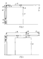
- Fig 3 shows the braking device 16 built together with the drop plumb 15 arranged on a self-closing standard type fire door 17, i.e. of the type which is normally kept open.
- the door 17 is retained in its open position by means of an anchor plate 18 connected to the door which is attracted by a firmly mounted electromagnet 19.
- the door 17 When the current is cut from the electromagnet 19, which may be effected by a safety fuse not shown, the door 17 will be closed by means of the drop plumb 15, which via the transmission chain 20 is connected to the suspension elements 21, connected to the upper edge of the door, the chain 20 for instance being routed inside the guide rail 20 of the door.
- the transmission chain 20 is routed through the plumb box 24 via a guide wheel 23.
- Fig 4 shows the braking device on a freely movable, self-closing door 25.
- the anchor plate 27 is retained in the open position by the electromagnet 26 and is here connected to the transmission chain 28, which is routed through a hole 29 in a carrier element 30 connected to the door. This can move freely to and fro along the chain 28 as long as the retaining device consisting of the anchor plate 27 and the magnet 26 is activated.
- the carrier element 30 is caught by the anchor plate 27, whereby the door moves towards its closed position.
- connection between the drop plumb and the door does not necessarily have to be a draw chain.
- a pull wire may be used, as long as a mainly slip free transmission between the wire and the transmission wheel of the braking device is ensured, e.g. by winding the wire twice around the transmission wheel, the latter having a substantially larger diameter than the wire, e.g. twenty times the diameter of the wire.
Landscapes
- Business, Economics & Management (AREA)
- Emergency Management (AREA)
- Power-Operated Mechanisms For Wings (AREA)
- Operating, Guiding And Securing Of Roll- Type Closing Members (AREA)
- Braking Arrangements (AREA)
Abstract
Description
- The invention relates to a braking device for self-closing doors of the type in which the closing movement is activated by means of a drop plumb which via an elongated flexible transmission element such as a pull wire can engage an element connected to the upper edge of the door.
- In self-closing doors such as, e.g. fire doors, the closing speed is often regulated by means of an automatic braking device, usually in the form of an eddy-current brake, the turnplate of which functions as a short-circuiting rotor and is connected to the transmission element, usually designed as a pull wire, and thereby is brought to revolve by the closing movement at a speed of rotation corresponding to the closing speed. At increasing speed of rotation the braking effect is increased.
- The known eddy-current brakes used for this purpose are most often designed as a bracket which, e.g. at sliding doors are firmly mounted in relation to the door opening at the upper edge thereof for connection with an element which corevolves with the closing movement of the pull wire. For use at sliding doors, the carrying wheels of which run in a rail that is open at the top, DK patent application No.5190/89 discloses an arrangement where the eddy-current brake is connected to one of the carrying wheels of the door running in said rail.
- Mounting the known braking devices at installation of new doors as well as on existing doors requires a rather comprehensive assembling work, and the braking device which, with a view to unimpeded movement in the opening direction, must be provided with an overrunning clutch between the turnplate functioning as short circuit rotor and said corevolving element, must be of a varying design depending on whether the door opens to the right or the left. In addition, installation of the known braking devices will often be unsightly, as it cannot be established as an embedded installation.
- The object of the invention is to provide a braking device, which can be used at all known types of self-closing doors, the closing movement of which is controlled by a drop plumb which normally moves in a closed plumb box, firmly mounted at one side of the door opening, and for which the mounting work is considerably reduced and the installation can be performed embedded.
- These and other objects of the invention can be met by a design of the braking device which is characterized in that the transmission element is routed mainly slip-free over a transmission wheel connected directly to the drop plumb and connected to a revolving braking device, such as an eddy-current brake.
- With the characteristic mounting of the braking device in connection with the drop plumb according to the invention the more laborious and often unsightly arrangement of the braking device as a separate bracket on the wall outside the door opening can be avoided. The braking device can also be used irrespective of whether the door is hinged in an open or a closed rail, and can be used on doors opening both to the left and to the right without altering its structure, and on standard types of self-opening doors which are normally kept open, as well as freely movable doors which allow manual opening and closing independently of the self-closing function.
- In addition, the braking device according to the invention can be used on sliding doors as well as rise-and-fall doors.
- The drop plumb and the braking device being in one unit, and the slip free connection to the elongated transmission element further entails an improved control of the closing movement, as the braking effect is exerted directly on the drop plumb.
- In a preferred embodiment, the drop plumb is connected with a U-profile which is open at the top, with said transmission wheel and a gear arranged between the transmission wheel and a shaft journal of the eddy-current brake mounted inside the U-profile, the turnplate of the eddy-current brake being placed outside one side wall of the U-profile opposite a ring of permanent magnets mounted on this side wall.
- A compact embodiment is hereby obtained, in which the braking device does not exceed the transverse dimensions of know drop plumbs.
- The invention is further explained in the following with reference to the drawing in which
- figs 1 and 2 are two side views of a preferred embodiment of the braking device according to the invention, and
- figs 3 and 4 show the use of the braking device on a standard type of a sliding door and a self-closing door, respectively, which also moves freely when operated manually.
- In the embodiment shown in figs 1 and 2, the drop plumb 1, having a square or rectangular cross section for running in a vertical plumb box at the closing side of a door opening, is connected to a U-profile 2 which is open at the top, between the vertical walls of which a
chain wheel 6 is arranged on a shaft with overrunningclutch 5 for engagement with a draw chain 7 comprising twochain sections 7a and 7b, of which the first one is firmly anchored in relation to the door opening at or above the upper position of the plumb when the door is in its open position, whereas the second one is connected to the upper edge of the door or to an element engaging therewith. Thechain wheel 6 can thus turn freely when the door moves towards its open position, but is locked in relation to theaxle 5, when the door moves towards its closed position. - The
chain wheel 6 is via a gear withgear wheels turnplate 10, placed outside one wall of the U-profile and functioning as short circuit rotor in an eddy-current braking device. Opposite the turnplate 10 a ring ofpermanent magnets 11 are mounted on the wall. For adjustment of the braking effect theturnplate 10 can be displaced on itsshaft 12, whereby the air gap between theturnplate 10 and themagnets 11 is adjusted. Adjustment can in the shown embodiment be done by more or less tightening of anut 13, against which theturnplate 10 abuts by means ofsaucer springs 14. - Fig 3 shows the
braking device 16 built together with thedrop plumb 15 arranged on a self-closing standardtype fire door 17, i.e. of the type which is normally kept open. Thedoor 17 is retained in its open position by means of an anchor plate 18 connected to the door which is attracted by a firmly mountedelectromagnet 19. - When the current is cut from the
electromagnet 19, which may be effected by a safety fuse not shown, thedoor 17 will be closed by means of thedrop plumb 15, which via thetransmission chain 20 is connected to thesuspension elements 21, connected to the upper edge of the door, thechain 20 for instance being routed inside theguide rail 20 of the door.
Thetransmission chain 20 is routed through theplumb box 24 via aguide wheel 23. - Fig 4 shows the braking device on a freely movable, self-closing
door 25. Theanchor plate 27 is retained in the open position by theelectromagnet 26 and is here connected to thetransmission chain 28, which is routed through ahole 29 in acarrier element 30 connected to the door. This can move freely to and fro along thechain 28 as long as the retaining device consisting of theanchor plate 27 and themagnet 26 is activated. When the retaining device is released, thecarrier element 30 is caught by theanchor plate 27, whereby the door moves towards its closed position. - Albeit preferable, the connection between the drop plumb and the door does not necessarily have to be a draw chain. A pull wire may be used, as long as a mainly slip free transmission between the wire and the transmission wheel of the braking device is ensured, e.g. by winding the wire twice around the transmission wheel, the latter having a substantially larger diameter than the wire, e.g. twenty times the diameter of the wire.
Claims (3)
- A braking device for self-closing doors of the type in which the closing movement is activated by means of a drop plumb (1) which via an elongated flexible transmission element (6), such as a pull wire can engage an element connected to the upper edge of the door, characterized in that the transmission element (7) is routed mainly slip-free over a transmission wheel (6) directly connected to the the drop plumb and to an automatic revolving braking device, such as an eddy-current brake.
- A braking device as claimed in claim 1, characterized in that the transmission element is a draw chain (7) and that said transmission wheel (6) engages the chain.
- A braking device as claimed in claim 1 or 2, characterized in that the drop plumb (1) is connected with a U-profile (2) open at the top, with the transmission wheel (6) and a gear (8, 9) between the wheel and a shaft journal of the eddy-current brake mounted inside the U-profile, the turnplate (10) of the eddy-current brake being placed outside one side wall (3) of the U-profile opposite a ring of permanent magnets (11) mounted on this side wall.
Priority Applications (1)
| Application Number | Priority Date | Filing Date | Title |
|---|---|---|---|
| EP92610061A EP0531246B1 (en) | 1991-09-04 | 1992-08-26 | A braking device for self-closing doors |
Applications Claiming Priority (3)
| Application Number | Priority Date | Filing Date | Title |
|---|---|---|---|
| EP91610074A EP0530425A1 (en) | 1991-09-04 | 1991-09-04 | A braking device for self closing doors |
| EP91610074 | 1991-09-04 | ||
| EP92610061A EP0531246B1 (en) | 1991-09-04 | 1992-08-26 | A braking device for self-closing doors |
Publications (2)
| Publication Number | Publication Date |
|---|---|
| EP0531246A1 true EP0531246A1 (en) | 1993-03-10 |
| EP0531246B1 EP0531246B1 (en) | 1995-12-13 |
Family
ID=8208787
Family Applications (2)
| Application Number | Title | Priority Date | Filing Date |
|---|---|---|---|
| EP91610074A Withdrawn EP0530425A1 (en) | 1991-09-04 | 1991-09-04 | A braking device for self closing doors |
| EP92610061A Expired - Lifetime EP0531246B1 (en) | 1991-09-04 | 1992-08-26 | A braking device for self-closing doors |
Family Applications Before (1)
| Application Number | Title | Priority Date | Filing Date |
|---|---|---|---|
| EP91610074A Withdrawn EP0530425A1 (en) | 1991-09-04 | 1991-09-04 | A braking device for self closing doors |
Country Status (5)
| Country | Link |
|---|---|
| EP (2) | EP0530425A1 (en) |
| AT (1) | ATE131569T1 (en) |
| DE (1) | DE69206722T2 (en) |
| DK (1) | DK0531246T3 (en) |
| NO (1) | NO178241C (en) |
Cited By (6)
| Publication number | Priority date | Publication date | Assignee | Title |
|---|---|---|---|---|
| WO1995024537A1 (en) * | 1994-03-09 | 1995-09-14 | N. Nørholm & K. Lemming A/S | A door closing apparatus for closing a hinged door |
| EP1186739A1 (en) * | 2000-09-04 | 2002-03-13 | N. Norholm & K. Lemming A/S | A device for controlling the closing movement of a sliding door |
| EP1306507A1 (en) * | 2001-10-24 | 2003-05-02 | N. Norholm & K. Lemming A/S | A method of making arrangements for controlling the closing movement of a sliding door |
| CN108808461A (en) * | 2018-07-12 | 2018-11-13 | 国网山东省电力公司济南市长清区供电公司 | A kind of transformer equipment mistaken opening preventer |
| EP3450317A1 (en) * | 2017-08-31 | 2019-03-06 | Driessen Aerospace Group N.V. | Slide extractor braking system |
| CN112160665A (en) * | 2020-09-27 | 2021-01-01 | 金梓拓 | Opening and closing structure of fireproof door in staircase |
Families Citing this family (5)
| Publication number | Priority date | Publication date | Assignee | Title |
|---|---|---|---|---|
| KR100240960B1 (en) * | 1997-08-19 | 2000-01-15 | 이종수 | Hoistway door close device of elevator |
| DE102006040070A1 (en) * | 2006-08-26 | 2008-02-28 | Daimler Ag | Motor vehicle has sliding door, eddy current brake device, which is formed in area of slide rail of sliding door, permanent magnet and electrically conducting element, which are arranged movable relative to each other |
| ITPD20070243A1 (en) * | 2007-07-18 | 2009-01-19 | Novoferm Schievano Srl | BRAKING DEVICE PARTICULARLY FOR FIREPROOF DOORS OF THE SLIDING TYPE |
| ES2393769B1 (en) * | 2011-05-12 | 2013-11-04 | Klein Ibérica, S.A. | AUTONOMOUS CLOSURE DEVICE FOR SLIDING DOORS. |
| FR3066931B1 (en) * | 2017-05-31 | 2019-07-19 | Claude Bertaux | SORBONNEL FRONT FACADE AUTOMATIC CLOSURE SYSTEM AND LABORATORY ENCLOSURES |
Citations (3)
| Publication number | Priority date | Publication date | Assignee | Title |
|---|---|---|---|---|
| DE668313C (en) * | 1937-04-21 | 1938-11-30 | Alexander Siewert | Brake device with time release for gates u. like |
| FR972425A (en) * | 1941-03-11 | 1951-01-30 | Benoto Sa | Return device for lifting equipment trolleys |
| EP0081189A2 (en) * | 1981-12-05 | 1983-06-15 | Karl-Heinz Linnig | Object braking device |
-
1991
- 1991-09-04 EP EP91610074A patent/EP0530425A1/en not_active Withdrawn
-
1992
- 1992-08-26 AT AT92610061T patent/ATE131569T1/en not_active IP Right Cessation
- 1992-08-26 DE DE69206722T patent/DE69206722T2/en not_active Expired - Fee Related
- 1992-08-26 EP EP92610061A patent/EP0531246B1/en not_active Expired - Lifetime
- 1992-08-26 DK DK92610061.1T patent/DK0531246T3/en active
- 1992-09-03 NO NO923444A patent/NO178241C/en unknown
Patent Citations (3)
| Publication number | Priority date | Publication date | Assignee | Title |
|---|---|---|---|---|
| DE668313C (en) * | 1937-04-21 | 1938-11-30 | Alexander Siewert | Brake device with time release for gates u. like |
| FR972425A (en) * | 1941-03-11 | 1951-01-30 | Benoto Sa | Return device for lifting equipment trolleys |
| EP0081189A2 (en) * | 1981-12-05 | 1983-06-15 | Karl-Heinz Linnig | Object braking device |
Cited By (8)
| Publication number | Priority date | Publication date | Assignee | Title |
|---|---|---|---|---|
| WO1995024537A1 (en) * | 1994-03-09 | 1995-09-14 | N. Nørholm & K. Lemming A/S | A door closing apparatus for closing a hinged door |
| EP1186739A1 (en) * | 2000-09-04 | 2002-03-13 | N. Norholm & K. Lemming A/S | A device for controlling the closing movement of a sliding door |
| EP1306507A1 (en) * | 2001-10-24 | 2003-05-02 | N. Norholm & K. Lemming A/S | A method of making arrangements for controlling the closing movement of a sliding door |
| EP3450317A1 (en) * | 2017-08-31 | 2019-03-06 | Driessen Aerospace Group N.V. | Slide extractor braking system |
| US10850847B2 (en) | 2017-08-31 | 2020-12-01 | Safran Cabin Netherlands N.v. | Slide extractor braking system |
| CN108808461A (en) * | 2018-07-12 | 2018-11-13 | 国网山东省电力公司济南市长清区供电公司 | A kind of transformer equipment mistaken opening preventer |
| CN108808461B (en) * | 2018-07-12 | 2020-03-06 | 国网山东省电力公司济南市长清区供电公司 | Anti-misopening device for substation equipment |
| CN112160665A (en) * | 2020-09-27 | 2021-01-01 | 金梓拓 | Opening and closing structure of fireproof door in staircase |
Also Published As
| Publication number | Publication date |
|---|---|
| EP0530425A1 (en) | 1993-03-10 |
| DE69206722T2 (en) | 1996-05-02 |
| NO178241B (en) | 1995-11-06 |
| ATE131569T1 (en) | 1995-12-15 |
| NO923444D0 (en) | 1992-09-03 |
| NO178241C (en) | 1996-02-14 |
| EP0531246B1 (en) | 1995-12-13 |
| NO923444L (en) | 1993-03-05 |
| DK0531246T3 (en) | 1996-03-18 |
| DE69206722D1 (en) | 1996-01-25 |
Similar Documents
| Publication | Publication Date | Title |
|---|---|---|
| EP0531246B1 (en) | A braking device for self-closing doors | |
| CA2651270C (en) | Overhead door locking operator | |
| EP1276951B1 (en) | Overhead door locking operator | |
| US4628636A (en) | Garage door operator mechanism | |
| EP0319036B1 (en) | A curtain drawing device | |
| HU216475B (en) | Electric lifting device | |
| AU4385496A (en) | An operating assembly for an electrically operated window screening device | |
| EP2651807A1 (en) | Monitoring device for detecting an undesired travel of an elevator cab from a standstill | |
| JPH11315662A (en) | Closer for sliding door | |
| US20100013424A1 (en) | Apparatus and method for controlling barrier movement | |
| US20110127112A1 (en) | Crash Safety Device Having a Rope Drive Mechanism | |
| BRPI0622155A2 (en) | set to control motion of an elevator car | |
| CH685221A5 (en) | Automatic operating drive for fire door | |
| US11643861B2 (en) | Release mechanism for a door operator | |
| DE3506740A1 (en) | Rotation damper for closing drives of revolving doors, sliding doors or the like | |
| DK0520934T3 (en) | Electric drive arrangement for a string winding and unwinding coil | |
| US3195617A (en) | Door operating mechanism | |
| DE8505458U1 (en) | Rotary damper for closing drives of swing doors, sliding doors or the like. | |
| CN109779436A (en) | A kind of pushing rotation stop formula door folding limiter of speed | |
| CN216714285U (en) | Take magnetism brake equipment's rolling slats door motor | |
| GB2260793A (en) | Apparatus for braking a member, particularly an opening ventilator flap biased to one of two positions | |
| JPH10266742A (en) | Electric shutter with emergency opening device | |
| KR20250088099A (en) | Bidirectional brake device for fire and security shutter | |
| JPH0543196Y2 (en) | ||
| PL222849B1 (en) | Device for moving gravitationally locked elements, especially fire partitions |
Legal Events
| Date | Code | Title | Description |
|---|---|---|---|
| PUAI | Public reference made under article 153(3) epc to a published international application that has entered the european phase |
Free format text: ORIGINAL CODE: 0009012 |
|
| AK | Designated contracting states |
Kind code of ref document: A1 Designated state(s): AT BE CH DE DK ES FR GB GR IT LI NL PT SE |
|
| 17P | Request for examination filed |
Effective date: 19930914 |
|
| RAP1 | Party data changed (applicant data changed or rights of an application transferred) |
Owner name: N. NOERHOLM & K. LEMMING A/S |
|
| 17Q | First examination report despatched |
Effective date: 19941024 |
|
| GRAA | (expected) grant |
Free format text: ORIGINAL CODE: 0009210 |
|
| AK | Designated contracting states |
Kind code of ref document: B1 Designated state(s): AT BE CH DE DK ES FR GB GR IT LI NL PT SE |
|
| PG25 | Lapsed in a contracting state [announced via postgrant information from national office to epo] |
Ref country code: NL Free format text: LAPSE BECAUSE OF FAILURE TO SUBMIT A TRANSLATION OF THE DESCRIPTION OR TO PAY THE FEE WITHIN THE PRESCRIBED TIME-LIMIT Effective date: 19951213 Ref country code: LI Effective date: 19951213 Ref country code: IT Free format text: LAPSE BECAUSE OF FAILURE TO SUBMIT A TRANSLATION OF THE DESCRIPTION OR TO PAY THE FEE WITHIN THE PRESCRIBED TIME-LIMIT;WARNING: LAPSES OF ITALIAN PATENTS WITH EFFECTIVE DATE BEFORE 2007 MAY HAVE OCCURRED AT ANY TIME BEFORE 2007. THE CORRECT EFFECTIVE DATE MAY BE DIFFERENT FROM THE ONE RECORDED. Effective date: 19951213 Ref country code: GR Free format text: LAPSE BECAUSE OF FAILURE TO SUBMIT A TRANSLATION OF THE DESCRIPTION OR TO PAY THE FEE WITHIN THE PRESCRIBED TIME-LIMIT Effective date: 19951213 Ref country code: ES Free format text: THE PATENT HAS BEEN ANNULLED BY A DECISION OF A NATIONAL AUTHORITY Effective date: 19951213 Ref country code: CH Effective date: 19951213 Ref country code: AT Effective date: 19951213 |
|
| REF | Corresponds to: |
Ref document number: 131569 Country of ref document: AT Date of ref document: 19951215 Kind code of ref document: T |
|
| BECA | Be: change of holder's address |
Free format text: 951213 N. *NOERHOLM & K. LEMMING A/S:ISLEVDALVEJ 100, DK-2610 RODOVRE |
|
| REF | Corresponds to: |
Ref document number: 69206722 Country of ref document: DE Date of ref document: 19960125 |
|
| PG25 | Lapsed in a contracting state [announced via postgrant information from national office to epo] |
Ref country code: PT Effective date: 19960313 |
|
| REG | Reference to a national code |
Ref country code: DK Ref legal event code: T3 |
|
| ET | Fr: translation filed | ||
| NLV1 | Nl: lapsed or annulled due to failure to fulfill the requirements of art. 29p and 29m of the patents act | ||
| REG | Reference to a national code |
Ref country code: CH Ref legal event code: PL |
|
| PG25 | Lapsed in a contracting state [announced via postgrant information from national office to epo] |
Ref country code: GB Effective date: 19960826 |
|
| PLBE | No opposition filed within time limit |
Free format text: ORIGINAL CODE: 0009261 |
|
| 26N | No opposition filed | ||
| GBPC | Gb: european patent ceased through non-payment of renewal fee |
Effective date: 19960826 |
|
| PG25 | Lapsed in a contracting state [announced via postgrant information from national office to epo] |
Ref country code: DK Free format text: LAPSE BECAUSE OF NON-PAYMENT OF DUE FEES Effective date: 19980826 |
|
| PGFP | Annual fee paid to national office [announced via postgrant information from national office to epo] |
Ref country code: DK Payment date: 20000818 Year of fee payment: 9 |
|
| REG | Reference to a national code |
Ref country code: DK Ref legal event code: EBP |
|
| PGFP | Annual fee paid to national office [announced via postgrant information from national office to epo] |
Ref country code: DE Payment date: 20070823 Year of fee payment: 16 |
|
| PGFP | Annual fee paid to national office [announced via postgrant information from national office to epo] |
Ref country code: BE Payment date: 20070806 Year of fee payment: 16 |
|
| PGFP | Annual fee paid to national office [announced via postgrant information from national office to epo] |
Ref country code: FR Payment date: 20070731 Year of fee payment: 16 |
|
| REG | Reference to a national code |
Ref country code: FR Ref legal event code: ST Effective date: 20090430 |
|
| PG25 | Lapsed in a contracting state [announced via postgrant information from national office to epo] |
Ref country code: BE Free format text: LAPSE BECAUSE OF NON-PAYMENT OF DUE FEES Effective date: 20080831 |
|
| PG25 | Lapsed in a contracting state [announced via postgrant information from national office to epo] |
Ref country code: FR Free format text: LAPSE BECAUSE OF NON-PAYMENT OF DUE FEES Effective date: 20080901 Ref country code: DE Free format text: LAPSE BECAUSE OF NON-PAYMENT OF DUE FEES Effective date: 20090303 |
|
| PGFP | Annual fee paid to national office [announced via postgrant information from national office to epo] |
Ref country code: SE Payment date: 20110824 Year of fee payment: 20 |