EP0531150B1 - Bellows tube installation device - Google Patents
Bellows tube installation device Download PDFInfo
- Publication number
- EP0531150B1 EP0531150B1 EP92308045A EP92308045A EP0531150B1 EP 0531150 B1 EP0531150 B1 EP 0531150B1 EP 92308045 A EP92308045 A EP 92308045A EP 92308045 A EP92308045 A EP 92308045A EP 0531150 B1 EP0531150 B1 EP 0531150B1
- Authority
- EP
- European Patent Office
- Prior art keywords
- tube
- bellows tube
- guide
- bellows
- distal end
- Prior art date
- Legal status (The legal status is an assumption and is not a legal conclusion. Google has not performed a legal analysis and makes no representation as to the accuracy of the status listed.)
- Expired - Lifetime
Links
- 238000009434 installation Methods 0.000 title claims description 34
- 238000006073 displacement reaction Methods 0.000 claims description 25
- 238000005259 measurement Methods 0.000 description 4
- 238000000034 method Methods 0.000 description 4
- 238000010276 construction Methods 0.000 description 2
- 238000007796 conventional method Methods 0.000 description 2
- 239000000463 material Substances 0.000 description 2
- 240000008100 Brassica rapa Species 0.000 description 1
- 230000002950 deficient Effects 0.000 description 1
- 230000000694 effects Effects 0.000 description 1
- 239000013307 optical fiber Substances 0.000 description 1
- 125000006850 spacer group Chemical group 0.000 description 1
Images





Classifications
-
- H—ELECTRICITY
- H01—ELECTRIC ELEMENTS
- H01B—CABLES; CONDUCTORS; INSULATORS; SELECTION OF MATERIALS FOR THEIR CONDUCTIVE, INSULATING OR DIELECTRIC PROPERTIES
- H01B13/00—Apparatus or processes specially adapted for manufacturing conductors or cables
- H01B13/012—Apparatus or processes specially adapted for manufacturing conductors or cables for manufacturing wire harnesses
- H01B13/01263—Tying, wrapping, binding, lacing, strapping or sheathing harnesses
-
- H—ELECTRICITY
- H02—GENERATION; CONVERSION OR DISTRIBUTION OF ELECTRIC POWER
- H02G—INSTALLATION OF ELECTRIC CABLES OR LINES, OR OF COMBINED OPTICAL AND ELECTRIC CABLES OR LINES
- H02G1/00—Methods or apparatus specially adapted for installing, maintaining, repairing or dismantling electric cables or lines
- H02G1/06—Methods or apparatus specially adapted for installing, maintaining, repairing or dismantling electric cables or lines for laying cables, e.g. laying apparatus on vehicle
- H02G1/08—Methods or apparatus specially adapted for installing, maintaining, repairing or dismantling electric cables or lines for laying cables, e.g. laying apparatus on vehicle through tubing or conduit, e.g. rod or draw wire for pushing or pulling
-
- Y—GENERAL TAGGING OF NEW TECHNOLOGICAL DEVELOPMENTS; GENERAL TAGGING OF CROSS-SECTIONAL TECHNOLOGIES SPANNING OVER SEVERAL SECTIONS OF THE IPC; TECHNICAL SUBJECTS COVERED BY FORMER USPC CROSS-REFERENCE ART COLLECTIONS [XRACs] AND DIGESTS
- Y10—TECHNICAL SUBJECTS COVERED BY FORMER USPC
- Y10T—TECHNICAL SUBJECTS COVERED BY FORMER US CLASSIFICATION
- Y10T29/00—Metal working
- Y10T29/53—Means to assemble or disassemble
- Y10T29/53696—Means to string
Definitions
- This invention relates to a bellows tube installation device for fitting a length of bellows tube over a filamentous body, such as electric wire.
- Fig. 15 is a sectional view of a bellows tube into which a length of electric wire is inserted.
- an electric wire W is sometimes received within a bellow tube T, as shown in Fig. 15, in order to protect the electric wire having connected thereto connectors at each end thereof so as to maintain flexibility of the wire.
- the electric wire W often constitute a portion of a wiring harness to which connectors C are connected at each end thereof, so that it is usually impossible to install the bellows tube T onto the electric wire W from one end thereof. Accordingly, installation of the bellows tube T onto such an electric wire W is conventionally performed by manually enlarging a slit D formed longitudinally in the bellows tube so as to insert the electric wire W into the bellows tube T through such an enlarged slit.
- US-A-4,593,442 discloses an apparatus including a handle attached to the end of which is a wedge-shaped separating member and a guide shoe.
- the apparatus is manually drawn along a pipe or tube and the separating member forces apart the edges of a longitudinal slit, creating a gap through which a cable may be fed. If, however, the pipe is of greater than normal resilience e.g. with bellows tubes, this manual method may be rather difficult and inefficient.
- FR-A-2 399 147 discloses a very different method for inserting wires into a casing.
- This comprises a fixed apparatus where electrical wires are unwound from rollers on one table, introduced by an operator into a guide tube, and slid along this tube so that they project from its opposite end. Cable is then unwound from a table at this end of the apparatus, and a fixed length threaded onto this end of the guide tube, thereby enclosing the wires.
- This method therefore disposes of the need to make a longitudinal slit in the casing, however, if connectors are present at both or either end of the wires, it may not be possible to use this apparatus.
- FR-A-1 568 848 discloses an apparatus which essentially consists of a spacer shoe mounted on a pulley driven by a motor.
- the shoe comprises two parts between which a cable may be placed.
- a casing which has a split running along its length, is passed over the pulley so that when it reaches the shoe it is forced apart along the split and the cable fed into it.
- a principle object of the invention is to provide a bellows tube installation device which permits easy installation of a bellows tube onto an electric wire, without the need of manual operation to enlarge a slit in the bellows tube.
- Another object of the invention is to provide a bellow tube installation device which permits automatic installation of a bellows tube having longitudinally extending slit onto a filamentous or elongated body.
- a bellows tube installation device comprising: a tube guide insertable into a bellows tube of a predetermined length, so that a filamentous body may be received within the bellows tube, the bellows tube being formed with a longitudinal slit, and the tube guide having a distal end which is configured to enlarge the slit of the bellows tube placed over the tube guide, so that the filamentous body may pass through the enlarged slit; and further comprising: means for setting the filamentous body at a position in which the filamentous body is adjacent the distal end of the tube guide, or a position in which the filamentous body intersects the distal end of the tube guide; a first clamp means for clampedly holding the bellows tube which is placed over the tube guide, the first clamp means being movable, together with the bellows tube clampedly held by the first clamp means, toward the distal end of the tube guide; a first displacement means for moving the first clamp means along the tube guide to
- the bellows tube installation device of the invention may further comprise a presser means for pressing the bellows tube moving, together with the second clamp means, toward the other end of the filamentous body at a position adjacent to the distal end portion of the tube guide and opposite to the side in which the slit is formed.
- the tube guide of the bellows tube installation device of the invention may include a guide protrusion extending longitudinally of the tube guide and protruding outwardly form the slit of the bellows tube place over the tube guide.
- a bellows tube having been placed over a tube guide form the proximal end thereof is calmpedly held by a first calmp means.
- the first clamp means holding the bellows tube is moved by a first displacement means so as to cause the bellows tube to be slid along the tube guide.
- the distal end or tip of the bellows tube reaches the distal end or tip of the tube guide, the distal end of the bellows is enlarge, i.e., opening of a slit in the distal end portion of the bellows tube is widened or increased.
- the tube guide with a guide protrusion which engages within the slit of the bellow tube placed over the tube guide so as to guide the bellows tube along the slit, thereby preventing the bellows tube form twisting.
- a bellows tube installation device as shown in Fig. 1 is adapted to fit a bellows tube T, having a slit D therein as explained above with reference to Fig. 15, over a length of electric wire W of a wiring harness.
- the illustrated bellows tube installation device comprises a tube guide 1, a guide displacement means 2, a harness positioning part 3, a first clamp means 4, a first displacement means 5, a second clamp means 6, a second displacement means 7, means for supplying bellows tubes 8, and a presser means 9.
- the tube guide 1 through presser means 9 are all mounted on a base 10.
- the tube guide 1 includes a pipe la constituting a guide body, and a guide protrusion 1b integrally provided in the periphery of the pipe la and extending longitudinally of the pipe la.
- the proximal portion la of the tube guide 1 defines an angle of 135 degrees with respect to a straight portion lc disposed distally of a gently curved portion or bend 1b and connected to the proximal portion la via the curved portion or bend.
- the guide tube 1 is maintained by the guide displacement means 2, which will be explained later, in a position in which the proximal portion la thereof is oriented in a vertical direction, while the straight portion lc is inclined 45 degrees with respect to the vertical direction.
- Fig. 3a is a sectional view along line IIIA-IIIA in Fig. 2, and fig. 3B is a view as seen from line IIIB-IIIB in Fig. 2.
- the distal end of the pipe A is formed into a flattened configuration having a lateral dimension greater than that of the remaining portion. Accordingly, and when the bellows tube T is fitted over the distal portion of the pipe 1A, slit portion D in the bellows tube T around the distal portion of the pipe 1A will be enlarged with respect to slit portion D in the bellows around the portion of the pipe other than the distal portion.
- the distal portion of the pipe 1A is configured so as to make the slit D in the bellows tube fitted over the distal portion of the pipe define an opening through which the electric wire W may be inserted into the bellows tube T.
- the pipe 1A is formed at its distal portion with a notch 1d disposed centrally along the transverse direction as seen in Fig. 3B. The notch 1d accommodates electric wire W in the harness secured to the harness positioning part 3.
- the guide displacement means 2 includes an air cylinder 3A secured to the base 10, and a guide support member 2B connected to a piston rod of the air cylinder 2A.
- the piston rod of the air cylinder 2A is reciprocal in a vertical direction.
- the rod support member 2B is secured to the guide protrusion 1B of the tube guide 1 at two, vertically spaced apart locations.
- the guide displacement means 2 is able to move the tube guide 1 in the vertical direction by means of actuation of the air cylinder 2A.
- the guide displacement means 2 moves the tube guide 1 between a position shown in Fig.
- the harness positioning part 3 is, as known in the art, is disposed so as to fix the harness at a position, whereby the electric wire W may be inserted into the notch ld formed in the distal end of the tube guide 1 in its lower limit position.
- the harness positioning part 3 of this embodiment is designed to secure connectors C connected to each end of the electric wire W to connector securement parts 3A, 3B, so as to set the electric wire W at a predetermined position.
- the connector securement parts 3A, 3B are mounted on a frame 3C secured to the base 10 at each end thereof.
- the connector securement parts 3A, 3B may be constituted, for example, by connectors associated with the respective connectors and fixed to the frame 3C.
- the connector securement parts 3A, 3B may have any suitable construction which permits the connectors C to be fixed so as to position the electric wire W at a predetermined position.
- the connector C may be clamped therebetween a pair of clamp members and secured by means of a screw.
- the first clamp means 4 is provided so as to clampedly hold the bellows tube T which is fitted over the tube guide 1 at a position slightly distal of the curved portion 1b of the tube guide 1.
- the first clamp means includes, as shown in Fig. 4, clamp members 4A, 4B being displaceable radially of the rube guide 1 and shaped symmetrically with each other, and a drive part 4C for driving the clamp members 4A. 4B.
- the clamp members 4A, 4B are designed to calmp the bellows tube T between recesses 4Aa, 4Ba formed in their respective confronting end surfaces, when the clamp members get close relative one another.
- the drive part 4C displaces the clamp members 4A, 4B in a direction of approaching relative one another or apart from one another.
- the drive part 4C includes two pistons disposed in a cylinder block. The pistons are moved simulaneously in opposite directions when the cylinder block is supplied with air.
- the clamp members 4A, 4B are moved in association with the piston.
- the thus constructed first clamp means 4 may be displaced along the tube guide 1 by the actuaiton of the first displacement means 5.
- the first diplacement means 5 includes a guide member 5A secured to the base 10, and a rodless cylinder 5B mounted on the guide member 5A and serving as a driving source.
- the guide member 5A includes a frame 5Aa having a "mirror image of C" configuration and located at a position distal of the curved portion 1b of the tube guide 1 and confronting relationship therewith, and two guide rods 5Ab disposed between the opposite ends of the frame 5Aa in parallel relationship with the axis of the tube guide 1 confronting to the guide rods.
- the rodless cylinder 5B includes an air cylinder body 5Ba disposed between the two guide rods 5Ab and fixed to the opposite ends of the frame 5Aa, and a movable block 5Bb to be moved in accordancae with movement of a piston (not shown) displaceable within the air cylinder body 5Ba.
- the movable block 5Bb and the piston in the air cylinder body 5Ba are combined together by means of magnetic attraction force exerted by their respective magnets.
- the drive part 4C of the first clamp means 4 is fixed to the movable block 5Bb.
- the second clamp means 6 is disposed at a position above the electric wire W positioned at the harness positioning part 3 and adjacent to the distal end of the tube guide 1.
- the second clamp means 6, as shown in Fig. 5, includes a pair of clamp members 6A, 6B, and an air cylinder 6C acting as a driving source.
- the rotational shaft 6a is journaled by an attachment member 6G, and the air cylinder 6C is secured to the attachment member 6G.
- a connection member 6D is secured to the piston rod of the air cylinder 6C, and the clamp members 6A, 6B are connected to links 6E, 6F, respectively, by means of the connection member 6D.
- the second clamp means 6 actuates the air cylinder 6C so as to displace the connection member 6D in vertical direction, whereby the clamp members 6A, 6B are rotated about the rotational shaft 6a.
- the clamp member 6A, 6B are opened, when the piston rod of the air cylinder 6C is retracted so as to locate the connection member 6D at an upward position.
- the clamp members 6A, 6B are rotated about the rotational shaft 6a in the direction of arrow marks in Fig. 5A.
- the clamp members 6A, 6B cooperate to clamp therebetween the bellows tube T which receives therein the electric wire W positioned at the harness positioning part 3.
- the second clamp means 6 may be displaced along the electric wire upon actuation of the second displacement means.
- the second displacement means 7 is constructed in substantially the same manner as the first displacement means 5.
- the second displacement means 7 includes a guide member 7A secured to the base 10, and a rodless cylinder 7B mounted on the guide member 7A for serving as a driving source.
- the guide member 7A includes a frame 7Aa having a "mirror image of U" shaped configuration and disposed at a position opposite to one end of the electric wire W, and two guide rods 7Ab disposed between the opposite ends of the electric wire W in parallel relationship with the longitudinal axis of the electric wire W opposed to the guide rods.
- the rodless cylinder 7B includes an air cylinder body 7Ba disposed between the two guide rods 7Ab and connected to the opposite ends of the frame 7Aa, and a displaceable block 7Bb to be moved in accordance with the movement of a piston (not shown) moving within the air cylinder body 7Ba.
- the movable block 7Bb and the piston in the air cylinder body 7Ba are combined together by means of magnetic attraction force exerted by their respective magnets.
- the air cylinder 6C of the second clamp means 6 is secured to the movable block 7Bb.
- the means for supplying bellows tube 8 is provided so as to supply bellows tubes 8 cut into a predetermined length to the guide rod 1.
- the bellows tube supplying means 8 includes a guide pulleys 8A, 8B, feed means 8C, length measurement means 8D, a tube guide 8E, and cutting means 8F.
- the guide pulleys 8A, 8B are rotatably supported by a frame 8G protruding upwardly from the base 10.
- the guide pulleys 8A, 8B supply a bellows tube T drawn from bellows tubes supply source (not shown) to the feed means 8C.
- the feed mans 8C includes a pair of rollers 8Ca, 8Ca journaled by a support frame 8H upstanding form the base 10 or a support frame 81 and being rotatable with the bellows tube T clamped between the respective outer circuferential surfaces of the rollers, and a feed motor 8Cb mounted on the support frame 81 with a drive shaft thereof connected to one of the feed rollers 8Ca. As shown in Fig. 8, actuation of the feed motor 8cb is controlled by a control signal sent from a drive circuit 8Cc.
- the feed rollers 8Ca, 8Ca each include a circumferential configuration of V groove-shaped configuration, as also shown in Fig. 7. Each outer circumferential surface of V groove-shaped configuration is formed with teeth for engagement with the outer periphery of the bellows tube T.
- the length measurement means 8D includes a pair of rubber rollers 8Da, 8Da journaled by the frame 8H or 8I for clampedly supporting the bellows tube T supplied from the feed means 8C at a position downstream of the feed means 8C.
- the rubber rollers 8Da, 8Da are rotated an amount corresponding to the displacement of the bellows tube clamped therebetween upon movement of the bellows tube T.
- the length measurement means 8D also includes a rotary encoder (not shown) mounted on a rotating shaft of one of the rubber rollers 8Da for unitary rotation with the rubber roller 8Da, and a photoelectric switch 8Db attached to the support frame 8H for measuring number of rotation of the rotary encoder. As shown in Fig. 8, an output from the photoelectric switch 9Db is signaled to a control unit 8Dc.
- the control unit 8Dc outputs a drive signal to an air supply 8Fc of an air cylinder 8Fb which will be explained later, when the number of rotation detected by the photoelectric switch 8Db reaches a predetermined value.
- a tube guide 8E is disposed and oriented vertically so that it may pass through between the feed rollers 8Ca, 8Ca and also between the rubber rollers 8Da, 8Da.
- the tube guide 8E has a configuration similar to that of the above guide tube 1 and includes, as shown in Figs. 8 and 9, a pipe 8Ea of a diameter the same as that of the pipe 1A, and a guide protrusion 8Eb having configuration the same as that of the guide protrusion 1B.
- the guide tube 8E is fixed to the support frame 81 with the lower end thereof disposed at a position above a path of a cutter 8Fa of a cutter means 8F which will be explained later and adjacent to the path.
- the proximal portion of the tube guide 1 and the tube guide 8E are disposed on a common axis.
- the cutter means 8F includes the above-mentioned cutter 8Fa (see Fig. 8) movable in a horizontal direction, and an air cylinder 8Fb for driving the cutter 8Fa (cutter 8Fa is not shown in Fig.1).
- the air cylinder 8Fb is actuated when a drive signal is supplied from the control unit 8Dc to the air supply 8Fc, so as to move the cutter 8Fa in a direction transverse to the portion at which the proximal end of the tube guide 1 and the tube guide 8E are opposed with each other, and then returning the cutter to its original position.
- the presser means 9 includes a presser rod 9A and an air cylinder 9B for driving the presser rod 9A.
- the air cylinder 9B is secured to the base 10 by means of an attachment plate 9C.
- the presser rod 9A is secured to a piston rod of the air cylinder 9B.
- the presser rod 9A is positioned above the electric wire W located at a predetermined position by means of the harness positioning part 3 when the piston rod of the air cylinder 9B is extended , so that it limits upward movement of the bellows tube T fitted over the electric wire W.
- the presser rod 9A is moved transversely or laterally from the position above the electric wire W.
- the bellows tube installation device constructed in accordance with the above serves to fit the bellows tube T over the electric wire W in a manner illustrated in Figs. 9 to 13.
- the bellows tube T introduced by means of the guide pulleys 8A, 8B is fitted over the tube guide 8E of the bellows tube installation device 8.
- the bellows tube T is moved in a path between the rollers 8Ca, 8Ca and rubber rollers 8Da, 8Da, so that the distal end of the bellows tube is positioned opposite to the blade edge of the cutter 8Fa.
- the connectors C at each end of the harness are secured to the connector securement parts 3A, 3B, respectively, of the harness positioning part 3, so that the electric wire W is located at a predetermined position.
- the bellows tube installation device In the position shown in Fig. 9, and when the motor 8Cb of the feed means 8C is energized , the bellows tube installation device first advances or moves downwardly the bellows tube T along the tube guide 8E by means of driving force of the feed rollers 8Ca, 8Ca. Thus, the bellows tube T begins to be fitted over the tube guide 1 at the proximal end of the tube guide.
- a stop signal is output from the control unit 8Dc of the length measurement means 8D to the drive circuit 8Cc of the motor 8Cb, and a drive signal is supplied to the air supply 8Fc (see Fig. 8).
- the motor 8Cb stops actuation of the feed rollers 8Ca, 8Ca in accordance with the above stop signal from the control unit 8Dc.
- the air cylinder 8Fb is actuated by the above drive signal from the control unit 8Dc, so that the cutter 8Fa intersects the bellows tube T so as to cut the bellows tube T.
- the air cylinder 2A of the guide displacement means 2 is actuated to as to extend to piston rod thereof, as illustrated in Fig. 11, so that the tube guide 1 fitted with the bellows tube T thereon is lowered to a position at which the electric wire W enters the notch ld formed at the distal end of the tube guide 1.
- the drive part 4C of the first clamp means 4 is actuated, so that the clamp member 4A, 4B cooperate to hold therebetween the bellows tube T fitted over the tube guide 1, as shown by dotted line in Fig. 4.
- the air cylinder 9B of the presser means 9 is actuated so that the presser rod 9A is located at a predetermined position on the electric wire W.
- the rodless cylinder 5B of the first displacement means 5 is then actuated, so that the movable block 5Bb of the rodless cylinder 5B is moved along the guide rod 5Ab.
- This movement causes the first clamp means 4 attached to the movable block 5Bb, together with the bellows tube clamped thereby, to be displaced distally or forwadly of the tube guide 1.
- the slit D of the bellows tube T is opened or enlarged at the distal end of the tube guide (see Fig. 3B). Further advancement of the bellows tube T causes the electric wire W to be inserted or housed within the bellows tube through the enlarged slit D, as shown by dotted line in Fig. 11.
- the electric wire W is securely inserted into the bellows tube T which has been transferred from the distal end of the tube guide 1 to the fixed part of the electric wire W, as the electric wire W is moved distally.
- the first clamp means 4 reaches lower limit position, the distal end of the bellows tube T has reached a position downstream of the lower part of the second clamp means 6.
- the bellows tube T is released form the clamp members 4A, 4B of the first clamp means 4, and at the same time, the air cylinder 6C of the second clamp means 6 is actuated, so that the bellows tube T is clamped between the clamp members 6A, 6B.
- the rodless cylinder 7B of the second displacement means 7 is actuated, so that the movable block 7Bb of the rodless cylinder 7B is moved along the guide rod 7Ab.
- the bellows tube T is also limited from upward movement at a position adjacent the distal end of the tube guide 1 by means of the presser rod 9A, so that the electric wire W is securely inserted into the bellows tube T which has been transferred from the distal end of the tube guide 1 to the fixed position of the electric wire W, as the electric wire W is moved distally.
- the bellows tube installation device permits the bellows tube T to be fitted over the electric wire W.
- the above-mentioned bellows tube installation device is designed so that a harness is manually located or positioned at the harness positioning part 3 after each installation of the bellows tube onto the electric wire of a harness has been competed.
- alternative harness positioning part may be employed in which a plurality of harnesses, arranged in parallel relationship, are provided in fixed manner, so that, as soon as a bellows tube T has been fitted over an electric wire W of preceding harness, next harness can be moved automatically to a position for installation of a bellows tube, so as to be replaced with the preceding harness.
- installation of bellows tubes T onto elctric wires may be automatically and continuously performed in repeated manner by means of the bellows tube installation device of the invention.
- an objective material which is fitted with a bellows tube by the bellows tube installation divice of the invention not necessarily be an electric wire as shown in the above embodiment.
- such objective material can be filamentous body such as optical fibers.
- first and second displacement means having a rodless cylinder as a power or driving source
- the first and second displacement means are not necessarily limited to such an illustrated embodiment, as long as they are able to suitably displace the first and second clamp means.
- the first and second clamp means are not necessarily limited to the illustrated embodiment, as far as they are able to appropriately and securely hold the bellows tube during movement of the first and second displacement means.
- the tip or distal end of the tube guide is located at a position at which it intersects the electric wire or filamentous body. It should be also understood that the distal end of the tube guide and the filamentous body or wire are not necessarily intersected with each other, but positioned adjacent with each other, provided that the opening of the slit of the bellows tube as enlarged by the distal end of the tube guide is maintained at suffcient openness sufficient to receive wire or filamentous body therein when the bellows tube intersects the filamentous body.
- the distal end of the tube guide is not necessarily configured as that shown in Fig.3, as long as it has configuration by which the slit of the bellows tube fitted over the tube guide can be enlarged.
- a tube guide 1' including a pipe 1A' having a constant diameter along its entire length and a guide protrusion 1B' formed integrally with the pipe 1A' and having an increased width at the distal end of the tube guide can also enlarge the slid D of the bellow tube T.
- the guide protrusion 1B' is deigned so as to engage a filamentous body, such as an electric wire located at a predetermined position.
- the present invention is advantageous in that operation of installing bellows tubes onto filamentous bodies may be performed in a short time with minimum operator's intervention, as well as achieving efficient productivity. Further, a filamentous body is accurately and securely inserted into the bellows tube which has been transferred form the distal end of the tube guide to the fixed part of the filamentous body, thereby minimizing occurrence of defective products. Furthermore, the bellows tube can be transferred to the fixed part of the filamentous body, without causing twisting thereof, with the slit thereof accurately opposed to the filamentous body.
Landscapes
- Engineering & Computer Science (AREA)
- Manufacturing & Machinery (AREA)
- Details Of Indoor Wiring (AREA)
- Automatic Assembly (AREA)
- Supply And Installment Of Electrical Components (AREA)
- Rigid Pipes And Flexible Pipes (AREA)
- Infusion, Injection, And Reservoir Apparatuses (AREA)
Description
- This invention relates to a bellows tube installation device for fitting a length of bellows tube over a filamentous body, such as electric wire.
- For convenience of illustration, a conventional method for fitting or installing electric wire into a bellows tube will be explained with reference to the attached drawings. Fig. 15 is a sectional view of a bellows tube into which a length of electric wire is inserted.
- In a electric wiring system for automobiles, for example, an electric wire W is sometimes received within a bellow tube T, as shown in Fig. 15, in order to protect the electric wire having connected thereto connectors at each end thereof so as to maintain flexibility of the wire. The electric wire W often constitute a portion of a wiring harness to which connectors C are connected at each end thereof, so that it is usually impossible to install the bellows tube T onto the electric wire W from one end thereof. Accordingly, installation of the bellows tube T onto such an electric wire W is conventionally performed by manually enlarging a slit D formed longitudinally in the bellows tube so as to insert the electric wire W into the bellows tube T through such an enlarged slit.
- In such a conventional method, it requires a substantial force to manually enlarge the slit, since the bellows tube T is not easily deformed upon application of a force in a radial direction, due to protrusions and recesses of the bellows tube serving as ribs to strengthen the bellows tube. Thus, it is very tiresome and not efficient to insert an electric wire W into a bellows tube T through a slit D while manually enlarging the slit.
- Further relevant prior art is contained in the following documents.
- US-A-4,593,442 discloses an apparatus including a handle attached to the end of which is a wedge-shaped separating member and a guide shoe. The apparatus is manually drawn along a pipe or tube and the separating member forces apart the edges of a longitudinal slit, creating a gap through which a cable may be fed. If, however, the pipe is of greater than normal resilience e.g. with bellows tubes, this manual method may be rather difficult and inefficient.
- FR-A-2 399 147 discloses a very different method for inserting wires into a casing. This comprises a fixed apparatus where electrical wires are unwound from rollers on one table, introduced by an operator into a guide tube, and slid along this tube so that they project from its opposite end. Cable is then unwound from a table at this end of the apparatus, and a fixed length threaded onto this end of the guide tube, thereby enclosing the wires. This method therefore disposes of the need to make a longitudinal slit in the casing, however, if connectors are present at both or either end of the wires, it may not be possible to use this apparatus.
- FR-A-1 568 848 discloses an apparatus which essentially consists of a spacer shoe mounted on a pulley driven by a motor. The shoe comprises two parts between which a cable may be placed. A casing, which has a split running along its length, is passed over the pulley so that when it reaches the shoe it is forced apart along the split and the cable fed into it. Thus an automatic method of inserting a cable into a casing is provided, although, again, this may be difficult to use if the cable has connectors at both ends.
- A principle object of the invention is to provide a bellows tube installation device which permits easy installation of a bellows tube onto an electric wire, without the need of manual operation to enlarge a slit in the bellows tube.
- Another object of the invention is to provide a bellow tube installation device which permits automatic installation of a bellows tube having longitudinally extending slit onto a filamentous or elongated body.
- In order to achieve the above object the present invention provides a bellows tube installation device comprising: a tube guide insertable into a bellows tube of a predetermined length, so that a filamentous body may be received within the bellows tube, the bellows tube being formed with a longitudinal slit, and the tube guide having a distal end which is configured to enlarge the slit of the bellows tube placed over the tube guide, so that the filamentous body may pass through the enlarged slit; and further comprising: means for setting the filamentous body at a position in which the filamentous body is adjacent the distal end of the tube guide, or a position in which the filamentous body intersects the distal end of the tube guide; a first clamp means for clampedly holding the bellows tube which is placed over the tube guide, the first clamp means being movable, together with the bellows tube clampedly held by the first clamp means, toward the distal end of the tube guide; a first displacement means for moving the first clamp means along the tube guide to a position in which one end portion of the filamentous body is partly inserted at least into the distal end portion of the bellows tube through the slit; a second clamp means for holding the bellows tube, at least the distal end portion of the bellows tube partly receiving the one end portion of filamentous body, at a position where the filamentous body is inserted into the bellows tube, the second clamp means being movable, together with the bellows tube clamped by the second clamp means, along the longitudinal axis of the filamentous body toward the other end of the filamentous body; and a second displacement means for moving the second clamp means.
- The bellows tube installation device of the invention may further comprise a presser means for pressing the bellows tube moving, together with the second clamp means, toward the other end of the filamentous body at a position adjacent to the distal end portion of the tube guide and opposite to the side in which the slit is formed.
- The tube guide of the bellows tube installation device of the invention may include a guide protrusion extending longitudinally of the tube guide and protruding outwardly form the slit of the bellows tube place over the tube guide.
- According to the bellows tube installation device of the invention, a bellows tube having been placed over a tube guide form the proximal end thereof is calmpedly held by a first calmp means. The first clamp means holding the bellows tube is moved by a first displacement means so as to cause the bellows tube to be slid along the tube guide. When the distal end or tip of the bellows tube reaches the distal end or tip of the tube guide, the distal end of the bellows is enlarge, i.e., opening of a slit in the distal end portion of the bellows tube is widened or increased. Further movement of the tube guide, together with the first clamp means, causes a filamentous body located or positioned adjacent the distal end of the tube guide to be received within the distal end of the bellows tube. The bellows tube through the enlarged slit of the bellows tube. The bellows tube having a filamentous body inserted within the distal end portion thereof is held by a second clamp means. The second clamp means holding the bellows tube is actuated by a second displacement means, so that it is moved toward the other end of the filamentous body along the fialmentous body. During this movement, the fialmentous body is gradually inserted into the bellows tube through the slit of the bellows tube.
- It is bossible to provide a presser means which serves to restrict the bellows tube, moving from the distal end of the tube guide to a fixed part of the filamentous body, from moving away from the filamentous body.
- It is also possible to provide the tube guide with a guide protrusion which engages within the slit of the bellow tube placed over the tube guide so as to guide the bellows tube along the slit, thereby preventing the bellows tube form twisting.
- For a better understanding of the invention, and to show how the same may be carried out into effect, reference will now be made, by way of example, to the accompanying drawings in which like reference numerals refer to like elements.
- Fig. 1 is a schematic front elevational view illustrating a bellows tube installation device according to the invention;
- Fig. 2 is an enlarged front elevational view of a tube guide;
- Fig. 3 is a view illustrating configuration of the tube gide;
- Fig. 4 is an enlarged view illustrating a first clamp means;
- Fig. 5 is an enlarged view illustrating a second clamp means;
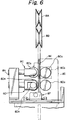
- Fig. 6 is a fragmentary side elevational view of a bellows tube supply means;
- Fig. 7 is a view showing a feed roller;
- Fig.8 is an illustration showing construction of the bellows tube supply means;
- Fig. 9 is an illustrative view showing one stage of installation of the bellows tube;
- Fig.10 is an illustrative view showing another stage of installation of the bellows tube;
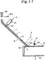
- Fig. 11 is an illustrative view showing further stage of installation of the bellows tube;
- Fig. 12 is an illustrative view showing another stage of installation of the bellows tube;
- Fig. 13 is an illustrative view showing further stage of installation of the bellows tube;
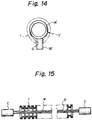
- Fig. 14 is an illustrative view of an alternative embodiment of the tube guide; and
- Fig. 15 is a sectional view illustrating electric wire over which the bellows tube is fitted.
- Several embodiments of bellows tube installation device according to the invention will be explained below with reference to Figs. 1 to 14.
- A bellows tube installation device according to one embodiment of the invention as shown in Fig. 1 is adapted to fit a bellows tube T, having a slit D therein as explained above with reference to Fig. 15, over a length of electric wire W of a wiring harness. The illustrated bellows tube installation device comprises a
tube guide 1, a guide displacement means 2, aharness positioning part 3, a first clamp means 4, a first displacement means 5, a second clamp means 6, a second displacement means 7, means for supplyingbellows tubes 8, and a presser means 9. Thetube guide 1 through presser means 9 are all mounted on abase 10. - As shown more clearly in Figs. 2 and 3, the
tube guide 1 includes a pipe la constituting a guide body, and a guide protrusion 1b integrally provided in the periphery of the pipe la and extending longitudinally of the pipe la. As shown in Fig. 1, the proximal portion la of thetube guide 1 defines an angle of 135 degrees with respect to a straight portion lc disposed distally of a gently curved portion or bend 1b and connected to the proximal portion la via the curved portion or bend. Theguide tube 1 is maintained by the guide displacement means 2, which will be explained later, in a position in which the proximal portion la thereof is oriented in a vertical direction, while the straight portion lc is inclined 45 degrees with respect to the vertical direction. - Fig. 3a is a sectional view along line IIIA-IIIA in Fig. 2, and fig. 3B is a view as seen from line IIIB-IIIB in Fig. 2. As shown in Fig. 3B, the distal end of the pipe A is formed into a flattened configuration having a lateral dimension greater than that of the remaining portion. Accordingly, and when the bellows tube T is fitted over the distal portion of the
pipe 1A, slit portion D in the bellows tube T around the distal portion of thepipe 1A will be enlarged with respect to slit portion D in the bellows around the portion of the pipe other than the distal portion. - The distal portion of the
pipe 1A is configured so as to make the slit D in the bellows tube fitted over the distal portion of the pipe define an opening through which the electric wire W may be inserted into the bellows tube T. Thepipe 1A is formed at its distal portion with anotch 1d disposed centrally along the transverse direction as seen in Fig. 3B. Thenotch 1d accommodates electric wire W in the harness secured to theharness positioning part 3. - The guide displacement means 2 includes an
air cylinder 3A secured to thebase 10, and aguide support member 2B connected to a piston rod of the air cylinder 2A. The piston rod of the air cylinder 2A is reciprocal in a vertical direction. Therod support member 2B is secured to theguide protrusion 1B of thetube guide 1 at two, vertically spaced apart locations. Thus, the guide displacement means 2 is able to move thetube guide 1 in the vertical direction by means of actuation of the air cylinder 2A. The guide displacement means 2 moves thetube guide 1 between a position shown in Fig. 10 in which the proximal portion of thetube guide 1 is disposed adjacent to a lower end of atube guide 8E, to be explained later, in the bellows tube supply means 8, and a position shown in Fig. 11 in which the distal end of thetube guide 1 and electric wire W are crossed with each other. In this regard, it is noted that, in the illustrated position in which the distal end of thetube guide 1 and the electric wire are crossed with each other, the electric wire W is received in the notch ld formed in the distal end of thetube guide 1. - The
harness positioning part 3 is, as known in the art, is disposed so as to fix the harness at a position, whereby the electric wire W may be inserted into the notch ld formed in the distal end of thetube guide 1 in its lower limit position. Theharness positioning part 3 of this embodiment is designed to secure connectors C connected to each end of the electric wire W toconnector securement parts - The
connector securement parts frame 3C secured to the base 10 at each end thereof. Theconnector securement parts frame 3C. In this regard, it should be noted that theconnector securement parts - The first clamp means 4 is provided so as to clampedly hold the bellows tube T which is fitted over the
tube guide 1 at a position slightly distal of the curved portion 1b of thetube guide 1. The first clamp means includes, as shown in Fig. 4,clamp members rube guide 1 and shaped symmetrically with each other, and adrive part 4C for driving theclamp members 4A. 4B. - The
clamp members drive part 4C displaces theclamp members drive part 4C includes two pistons disposed in a cylinder block. The pistons are moved simulaneously in opposite directions when the cylinder block is supplied with air. Theclamp members tube guide 1 by the actuaiton of the first displacement means 5. - The first diplacement means 5 includes a
guide member 5A secured to thebase 10, and a rodless cylinder 5B mounted on theguide member 5A and serving as a driving source. Theguide member 5A includes a frame 5Aa having a "mirror image of C" configuration and located at a position distal of the curved portion 1b of thetube guide 1 and confronting relationship therewith, and two guide rods 5Ab disposed between the opposite ends of the frame 5Aa in parallel relationship with the axis of thetube guide 1 confronting to the guide rods. - The rodless cylinder 5B includes an air cylinder body 5Ba disposed between the two guide rods 5Ab and fixed to the opposite ends of the frame 5Aa, and a movable block 5Bb to be moved in accordancae with movement of a piston (not shown) displaceable within the air cylinder body 5Ba. The movable block 5Bb and the piston in the air cylinder body 5Ba are combined together by means of magnetic attraction force exerted by their respective magnets. The
drive part 4C of the first clamp means 4 is fixed to the movable block 5Bb. - The second clamp means 6 is disposed at a position above the electric wire W positioned at the
harness positioning part 3 and adjacent to the distal end of thetube guide 1. The second clamp means 6, as shown in Fig. 5, includes a pair ofclamp members air cylinder 6C acting as a driving source. Therotational shaft 6a is journaled by anattachment member 6G, and theair cylinder 6C is secured to theattachment member 6G. Aconnection member 6D is secured to the piston rod of theair cylinder 6C, and theclamp members links connection member 6D. - The second clamp means 6 actuates the
air cylinder 6C so as to displace theconnection member 6D in vertical direction, whereby theclamp members rotational shaft 6a. Specifically, and as shown in Fig. A, theclamp member air cylinder 6C is retracted so as to locate theconnection member 6D at an upward position. When the poston rod is extended from the above position, theclamp members rotational shaft 6a in the direction of arrow marks in Fig. 5A. As illustrated in Fig. 5B, theclamp members harness positioning part 3. The second clamp means 6 may be displaced along the electric wire upon actuation of the second displacement means. - The second displacement means is constructed in substantially the same manner as the first displacement means 5. Specifically, the second displacement means 7 includes a
guide member 7A secured to thebase 10, and arodless cylinder 7B mounted on theguide member 7A for serving as a driving source. Theguide member 7A includes a frame 7Aa having a "mirror image of U" shaped configuration and disposed at a position opposite to one end of the electric wire W, and two guide rods 7Ab disposed between the opposite ends of the electric wire W in parallel relationship with the longitudinal axis of the electric wire W opposed to the guide rods. Therodless cylinder 7B includes an air cylinder body 7Ba disposed between the two guide rods 7Ab and connected to the opposite ends of the frame 7Aa, and a displaceable block 7Bb to be moved in accordance with the movement of a piston (not shown) moving within the air cylinder body 7Ba. The movable block 7Bb and the piston in the air cylinder body 7Ba are combined together by means of magnetic attraction force exerted by their respective magnets. Theair cylinder 6C of the second clamp means 6 is secured to the movable block 7Bb. - The means for supplying
bellows tube 8 is provided so as to supplybellows tubes 8 cut into a predetermined length to theguide rod 1. As also shown in Fig.6, the bellowstube supplying means 8 includes a guide pulleys 8A, 8B, feed means 8C, length measurement means 8D, atube guide 8E, and cutting means 8F. - The guide pulleys 8A, 8B are rotatably supported by a
frame 8G protruding upwardly from thebase 10. The guide pulleys 8A, 8B supply a bellows tube T drawn from bellows tubes supply source (not shown) to the feed means 8C. - The
feed mans 8C includes a pair of rollers 8Ca, 8Ca journaled by asupport frame 8H upstanding form the base 10 or asupport frame 81 and being rotatable with the bellows tube T clamped between the respective outer circuferential surfaces of the rollers, and a feed motor 8Cb mounted on thesupport frame 81 with a drive shaft thereof connected to one of the feed rollers 8Ca. As shown in Fig. 8, actuation of the feed motor 8cb is controlled by a control signal sent from a drive circuit 8Cc. The feed rollers 8Ca, 8Ca each include a circumferential configuration of V groove-shaped configuration, as also shown in Fig. 7. Each outer circumferential surface of V groove-shaped configuration is formed with teeth for engagement with the outer periphery of the bellows tube T. - The length measurement means 8D includes a pair of rubber rollers 8Da, 8Da journaled by the
frame 8H or 8I for clampedly supporting the bellows tube T supplied from the feed means 8C at a position downstream of the feed means 8C. The rubber rollers 8Da, 8Da are rotated an amount corresponding to the displacement of the bellows tube clamped therebetween upon movement of the bellows tube T. - The length measurement means 8D also includes a rotary encoder (not shown) mounted on a rotating shaft of one of the rubber rollers 8Da for unitary rotation with the rubber roller 8Da, and a photoelectric switch 8Db attached to the
support frame 8H for measuring number of rotation of the rotary encoder. As shown in Fig. 8, an output from the photoelectric switch 9Db is signaled to a control unit 8Dc. - The control unit 8Dc outputs a drive signal to an air supply 8Fc of an air cylinder 8Fb which will be explained later, when the number of rotation detected by the photoelectric switch 8Db reaches a predetermined value.
- A
tube guide 8E is disposed and oriented vertically so that it may pass through between the feed rollers 8Ca, 8Ca and also between the rubber rollers 8Da, 8Da. Thetube guide 8E has a configuration similar to that of theabove guide tube 1 and includes, as shown in Figs. 8 and 9, a pipe 8Ea of a diameter the same as that of thepipe 1A, and a guide protrusion 8Eb having configuration the same as that of theguide protrusion 1B. Theguide tube 8E is fixed to thesupport frame 81 with the lower end thereof disposed at a position above a path of a cutter 8Fa of a cutter means 8F which will be explained later and adjacent to the path. The proximal portion of thetube guide 1 and thetube guide 8E are disposed on a common axis. - The cutter means 8F includes the above-mentioned cutter 8Fa (see Fig. 8) movable in a horizontal direction, and an air cylinder 8Fb for driving the cutter 8Fa (cutter 8Fa is not shown in Fig.1). As explained above, the air cylinder 8Fb is actuated when a drive signal is supplied from the control unit 8Dc to the air supply 8Fc, so as to move the cutter 8Fa in a direction transverse to the portion at which the proximal end of the
tube guide 1 and thetube guide 8E are opposed with each other, and then returning the cutter to its original position. - The presser means 9 includes a
presser rod 9A and anair cylinder 9B for driving thepresser rod 9A. Theair cylinder 9B is secured to thebase 10 by means of anattachment plate 9C. Thepresser rod 9A is secured to a piston rod of theair cylinder 9B. Thepresser rod 9A is positioned above the electric wire W located at a predetermined position by means of theharness positioning part 3 when the piston rod of theair cylinder 9B is extended , so that it limits upward movement of the bellows tube T fitted over the electric wire W. When the piston rod of theair cylinder 9A is withdrawn or retracted, thepresser rod 9A is moved transversely or laterally from the position above the electric wire W. - The bellows tube installation device constructed in accordance with the above serves to fit the bellows tube T over the electric wire W in a manner illustrated in Figs. 9 to 13.
- Prior to actuating the bellows tube installation divice, the bellows tube T introduced by means of the guide pulleys 8A, 8B is fitted over the
tube guide 8E of the bellowstube installation device 8. The bellows tube T is moved in a path between the rollers 8Ca, 8Ca and rubber rollers 8Da, 8Da, so that the distal end of the bellows tube is positioned opposite to the blade edge of the cutter 8Fa. As shown by dotted line in Fig. 1, the connectors C at each end of the harness are secured to theconnector securement parts harness positioning part 3, so that the electric wire W is located at a predetermined position. - In the position shown in Fig. 9, and when the motor 8Cb of the feed means 8C is energized , the bellows tube installation device first advances or moves downwardly the bellows tube T along the
tube guide 8E by means of driving force of the feed rollers 8Ca, 8Ca. Thus, the bellows tube T begins to be fitted over thetube guide 1 at the proximal end of the tube guide. - After the bellows tube T has been advanced predetermined amount or distance, a stop signal is output from the control unit 8Dc of the length measurement means 8D to the drive circuit 8Cc of the motor 8Cb, and a drive signal is supplied to the air supply 8Fc (see Fig. 8). The motor 8Cb stops actuation of the feed rollers 8Ca, 8Ca in accordance with the above stop signal from the control unit 8Dc. The air cylinder 8Fb is actuated by the above drive signal from the control unit 8Dc, so that the cutter 8Fa intersects the bellows tube T so as to cut the bellows tube T.
- When the bellows tube T has been cut by the cutter 8Fa in the above manner, the air cylinder 2A of the guide displacement means 2 is actuated to as to extend to piston rod thereof, as illustrated in Fig. 11, so that the
tube guide 1 fitted with the bellows tube T thereon is lowered to a position at which the electric wire W enters the notch ld formed at the distal end of thetube guide 1. - When the
tube guide 1 has been lowered, thedrive part 4C of the first clamp means 4 is actuated, so that theclamp member tube guide 1, as shown by dotted line in Fig. 4. Simultaneously, theair cylinder 9B of the presser means 9 is actuated so that thepresser rod 9A is located at a predetermined position on the electric wire W. - The rodless cylinder 5B of the first displacement means 5 is then actuated, so that the movable block 5Bb of the rodless cylinder 5B is moved along the guide rod 5Ab. This movement causes the first clamp means 4 attached to the movable block 5Bb, together with the bellows tube clamped thereby, to be displaced distally or forwadly of the
tube guide 1. When the bellows tube T has reached the distal end of thetube guide 1, the slit D of the bellows tube T is opened or enlarged at the distal end of the tube guide (see Fig. 3B). Further advancement of the bellows tube T causes the electric wire W to be inserted or housed within the bellows tube through the enlarged slit D, as shown by dotted line in Fig. 11. - During above period, upward movement of the bellows tube T adjacent to the distal end of the
guide tube 1 is limited by means of thepresser rod 9A. Accordingly, the bellows tube T is prevented form moving upwardly or escaping, even when the electric wire W engages with the circumferential edge around the slit of the bellows tube T. - Thus, the electric wire W is securely inserted into the bellows tube T which has been transferred from the distal end of the
tube guide 1 to the fixed part of the electric wire W, as the electric wire W is moved distally. When the first clamp means 4 reaches lower limit position, the distal end of the bellows tube T has reached a position downstream of the lower part of the second clamp means 6. - When the first clamp means 4 has reached the lower limit position, the bellows tube T is released form the
clamp members air cylinder 6C of the second clamp means 6 is actuated, so that the bellows tube T is clamped between theclamp members - In the position shown in Fig. 2, the
rodless cylinder 7B of the second displacement means 7 is actuated, so that the movable block 7Bb of therodless cylinder 7B is moved along the guide rod 7Ab. This causes the second clamp means 6 attached to the movable block 7Bb, together with the bellows tube T held by the second clamp means 6, to be moved toward the distal end of the electric wire W, as shown in Fig. 13. During the above period, the bellows tube T is also limited from upward movement at a position adjacent the distal end of thetube guide 1 by means of thepresser rod 9A, so that the electric wire W is securely inserted into the bellows tube T which has been transferred from the distal end of thetube guide 1 to the fixed position of the electric wire W, as the electric wire W is moved distally. - As will be appreciated from the foregoing, the bellows tube installation device according to the invention permits the bellows tube T to be fitted over the electric wire W. The above-mentioned bellows tube installation device is designed so that a harness is manually located or positioned at the
harness positioning part 3 after each installation of the bellows tube onto the electric wire of a harness has been competed. It will be appreciated, however, that alternative harness positioning part may be employed in which a plurality of harnesses, arranged in parallel relationship, are provided in fixed manner, so that, as soon as a bellows tube T has been fitted over an electric wire W of preceding harness, next harness can be moved automatically to a position for installation of a bellows tube, so as to be replaced with the preceding harness. With such a harness positioning part, installation of bellows tubes T onto elctric wires may be automatically and continuously performed in repeated manner by means of the bellows tube installation device of the invention. - It should be noted that an objective material which is fitted with a bellows tube by the bellows tube installation divice of the invention not necessarily be an electric wire as shown in the above embodiment. for example, such objective material can be filamentous body such as optical fibers. While in the above embodiment first and second displacement means having a rodless cylinder as a power or driving source, it should be noted that the first and second displacement means are not necessarily limited to such an illustrated embodiment, as long as they are able to suitably displace the first and second clamp means. Similarly, the first and second clamp means are not necessarily limited to the illustrated embodiment, as far as they are able to appropriately and securely hold the bellows tube during movement of the first and second displacement means.
- In the illustrated embodiment, the tip or distal end of the tube guide is located at a position at which it intersects the electric wire or filamentous body. It should be also understood that the distal end of the tube guide and the filamentous body or wire are not necessarily intersected with each other, but positioned adjacent with each other, provided that the the opening of the slit of the bellows tube as enlarged by the distal end of the tube guide is maintained at suffcient openness sufficient to receive wire or filamentous body therein when the bellows tube intersects the filamentous body. The distal end of the tube guide is not necessarily configured as that shown in Fig.3, as long as it has configuration by which the slit of the bellows tube fitted over the tube guide can be enlarged.
- For example, and as shown in Fig. 14, a tube guide 1' including a
pipe 1A' having a constant diameter along its entire length and aguide protrusion 1B' formed integrally with thepipe 1A' and having an increased width at the distal end of the tube guide can also enlarge the slid D of the bellow tube T. In this embodiment, it is desirable that theguide protrusion 1B' is deigned so as to engage a filamentous body, such as an electric wire located at a predetermined position. - In accordance with the present invention, it is possible to insert a filamentous body into a bellows tube through a slit formed in the bellows tube, the openness of the slit being automatically enlarged or increased by displacing the bellows tube along the tube guide. Accordingly, the present invention is advantageous in that operation of installing bellows tubes onto filamentous bodies may be performed in a short time with minimum operator's intervention, as well as achieving efficient productivity. Further, a filamentous body is accurately and securely inserted into the bellows tube which has been transferred form the distal end of the tube guide to the fixed part of the filamentous body, thereby minimizing occurrence of defective products. Furthermore, the bellows tube can be transferred to the fixed part of the filamentous body, without causing twisting thereof, with the slit thereof accurately opposed to the filamentous body.
- The principles, preferred embodiments and modes of operation of the present invention have been described in the foregoing specification. The invention which is intended to be protected herein should not, however, be construed which is to be regarded as illustrative rather than restrictive. Variations and changes may be made by those skilled in the art. Accordingly, the foregoing detailed description should be regarded as exemplary in nature and not as limiting the scope of the invention set forth in the appended Claims.
Claims (3)
- A bellows tube installation device comprising: a tube guide (1) insertable into a bellows tube (T) of a predetermined length, so that a filamentous body may be received within said bellows tube (T),characterised in that:said bellows tube (T) is formed with a longitudinal slit (D), said tube guide (1) having a distal end (lA) which is configured to enlarge said slit (D) of said bellows tube (T) placed over said tube guide (1), so that said filamentous body may pass through said enlarged slit,and further comprising:means (3) for setting said filamentous body at a position in which said filamentous body is adjacent the distal end (lA) of said tube guide (1), or a position in which said filamentous body intersects said distal end (1A) of said tube guide (1),a first clamp means (4) for clampedly holding said bellows tube (T) which is placed over said tube guide (1), said first clamp means (4) being movable, together with said bellows tube (T) clampedly held by said first clamp means (4), toward the distal end (1A) of said tube guide (1),a first displacement means (5) for moving said first clamp means (4) along said tube guide (1) to a position in which one end portion of said filamentous body is partly inserted at least into the distal end portion of said bellows tube (T) through said slit (D),a second clamp means (6) for holding said bellows tube (T), at least said distal end portion of said bellows tube (T) partly receiving said one end portion of said filamentous body, at a position where said filamentous body is inserted into said bellows tube (T), said second clamp means (6) being movable, together with said bellows tube (T) clamped by said second clamp means (6), along the longitudinal axis of said filamentous body toward the other end of said filamentous body, anda second displacement means (7) for moving said second clamp means (6).
- A bellows tube installation device according to claim 1, further comprising a presser means (9) for pressing said bellows tube (T) moving, together with said second clamp means (6), toward the other end of said filamentous body at a position adjacent to said distal end (1A) of said tube guide (1) and opposite to the side in which said slit (D) is formed.
- A bellow tube installation device according to claim 1 or claim 2, wherein said tube guide (1) comprising a guide protrusion (1b) extending longitudinally of said tube guide (1) and protruding outwardly from said slit (D) of said bellows tube (T) placed over said tube guide (1).
Applications Claiming Priority (2)
| Application Number | Priority Date | Filing Date | Title |
|---|---|---|---|
| JP253166/91 | 1991-09-04 | ||
| JP3253166A JP2611583B2 (en) | 1991-09-04 | 1991-09-04 | Bellows tube mounting device |
Publications (3)
| Publication Number | Publication Date |
|---|---|
| EP0531150A2 EP0531150A2 (en) | 1993-03-10 |
| EP0531150A3 EP0531150A3 (en) | 1993-04-21 |
| EP0531150B1 true EP0531150B1 (en) | 1996-01-17 |
Family
ID=17247452
Family Applications (1)
| Application Number | Title | Priority Date | Filing Date |
|---|---|---|---|
| EP92308045A Expired - Lifetime EP0531150B1 (en) | 1991-09-04 | 1992-09-04 | Bellows tube installation device |
Country Status (4)
| Country | Link |
|---|---|
| US (1) | US5228179A (en) |
| EP (1) | EP0531150B1 (en) |
| JP (1) | JP2611583B2 (en) |
| DE (1) | DE69207682T2 (en) |
Families Citing this family (17)
| Publication number | Priority date | Publication date | Assignee | Title |
|---|---|---|---|---|
| DE19536907C2 (en) * | 1995-01-11 | 1998-03-19 | Pro Eff Gmbh Entwicklung Von P | Device for the mechanical sheathing of cables, cable harnesses or lines |
| EP0742624A1 (en) * | 1995-05-02 | 1996-11-13 | SIX TAU S.p.A. | A device for inserting a bundle of cables into a protective conduit of plastics material |
| US5634252A (en) * | 1996-03-26 | 1997-06-03 | Honeywell Inc. | Apparatus for attaching protective tubing to a component |
| US6749179B2 (en) | 2002-03-13 | 2004-06-15 | Board Of Regents, The University Of Texas System | Devices and methods for placing wiring into split loom tubing |
| CN101695809B (en) * | 2009-10-30 | 2011-12-28 | 宁波伏尔肯机械密封件制造有限公司 | Assembly machine for mechanical seal of rubber bellows |
| CN103252632B (en) * | 2013-02-21 | 2015-09-02 | 浙江吉利罗佑发动机有限公司 | A kind of heater inlet pipe installation tool |
| CN103770128A (en) * | 2014-01-23 | 2014-05-07 | 宝鸡南车时代工程机械有限公司 | Tube sectioning cutter for sectioning harness conduit |
| WO2015182437A1 (en) * | 2014-05-29 | 2015-12-03 | 矢崎総業株式会社 | Cover member fitting device and cover member fitting method |
| JP6282937B2 (en) * | 2014-05-29 | 2018-02-21 | 矢崎総業株式会社 | Tape winding apparatus and tape winding method |
| JP6282938B2 (en) * | 2014-05-29 | 2018-02-21 | 矢崎総業株式会社 | Exterior member attaching device and exterior member attaching method |
| JP6422359B2 (en) * | 2015-02-12 | 2018-11-14 | 矢崎総業株式会社 | Insertion device and method of manufacturing electric wire with exterior member |
| JP6674316B2 (en) * | 2016-05-13 | 2020-04-01 | 矢崎総業株式会社 | Corrugated tube mounting device and corrugated tube mounting method |
| CN110718880B (en) * | 2019-11-18 | 2025-03-07 | 郑州赛川电子科技有限公司 | A cycloid mechanism and cable tube threading equipment |
| CN110707604B (en) * | 2019-11-18 | 2025-03-07 | 郑州赛川电子科技有限公司 | A wire threading mechanism and cable pipe threading equipment |
| CN111768930B (en) * | 2020-07-30 | 2022-07-12 | 安徽省亿嘉弘电器股份有限公司 | Wire harness ant-proof pipe mounting device |
| CN112372578A (en) * | 2020-12-24 | 2021-02-19 | 广西方鑫汽车科技有限公司 | Automatic cold inserting equipment for nylon pipe of fuel tank |
| JP7760223B2 (en) * | 2024-02-07 | 2025-10-27 | 矢崎総業株式会社 | Automatic twist tube mounting device |
Family Cites Families (5)
| Publication number | Priority date | Publication date | Assignee | Title |
|---|---|---|---|---|
| FR1568848A (en) * | 1967-12-29 | 1969-05-30 | ||
| US3874061A (en) * | 1973-05-30 | 1975-04-01 | Cofpa | Wire inserting device |
| FR2399147A1 (en) * | 1977-07-27 | 1979-02-23 | Seinem Sa | Automatic high-speed insulating machine - uses rigid guide tube to aid passage of insulating sheath over bundle of wires |
| US4593442A (en) * | 1985-06-17 | 1986-06-10 | Wright Curtis M | Cable installation apparatus |
| CA1305095C (en) * | 1988-03-25 | 1992-07-14 | Kiyomi Yokoi | Method and apparatus for passing threadlike pieces through tubular products |
-
1991
- 1991-09-04 JP JP3253166A patent/JP2611583B2/en not_active Expired - Fee Related
-
1992
- 1992-09-03 US US07/939,668 patent/US5228179A/en not_active Expired - Lifetime
- 1992-09-04 EP EP92308045A patent/EP0531150B1/en not_active Expired - Lifetime
- 1992-09-04 DE DE69207682T patent/DE69207682T2/en not_active Expired - Fee Related
Also Published As
| Publication number | Publication date |
|---|---|
| JP2611583B2 (en) | 1997-05-21 |
| DE69207682T2 (en) | 1996-05-30 |
| JPH0569245A (en) | 1993-03-23 |
| EP0531150A2 (en) | 1993-03-10 |
| EP0531150A3 (en) | 1993-04-21 |
| US5228179A (en) | 1993-07-20 |
| DE69207682D1 (en) | 1996-02-29 |
Similar Documents
| Publication | Publication Date | Title |
|---|---|---|
| EP0531150A2 (en) | Bellows tube installation device | |
| KR0182069B1 (en) | Cutting blade bending system | |
| US3324536A (en) | Coil assembling apparatus | |
| EP0707365B1 (en) | Multiple blade set strip apparatus for cable and wire | |
| US4593442A (en) | Cable installation apparatus | |
| US5281289A (en) | Process for the manufacturing of a tire and machines for the carrying out of the process | |
| UA46789C2 (en) | METHOD OF DIRECTION TO REPLACEMENT OF TORN FIBER FOR WINDING ON A COIL | |
| JP3461370B2 (en) | Cable feed and change equipment for cable processing machines | |
| KR930010587B1 (en) | Guide devices for wire or strip-shaped cutting electrodes on machine tools | |
| US4062110A (en) | Portable tool for stripping metal sheathing from heavy conductive cable | |
| GB2277102A (en) | "Cable coiler with coil stripper" | |
| WO1999009625A2 (en) | Improved wire cutting and stripping apparatus | |
| EP1327295A1 (en) | Machine for winding dynamo-electric stators | |
| US4253222A (en) | Apparatus for applying assembled connector terminals to a plurality of leads | |
| SE511557C2 (en) | Applicator for detachable mounting in a connection crimping machine | |
| CN211803567U (en) | Gas-cooker thermocouple wire unloader | |
| US4594771A (en) | Apparatus and method for automatically inserting coils and wedges into a stator core of any given length | |
| JPH07272816A (en) | Cable sending device for automatic connection device | |
| KR0164428B1 (en) | Harness making machine having improved cable guide | |
| CN210489305U (en) | A kind of wire harness automatic spot winding equipment and stranding machine | |
| EP0244123A1 (en) | Cable supporting apparatus | |
| JP7657911B2 (en) | Automatic cutting machine | |
| KR100355578B1 (en) | Spring manufacturing device | |
| CN112938645A (en) | Wire and cable cutting machine with receive material structure | |
| CN217492526U (en) | Automatic pneumatic wire cutting machine |
Legal Events
| Date | Code | Title | Description |
|---|---|---|---|
| PUAI | Public reference made under article 153(3) epc to a published international application that has entered the european phase |
Free format text: ORIGINAL CODE: 0009012 |
|
| PUAL | Search report despatched |
Free format text: ORIGINAL CODE: 0009013 |
|
| 17P | Request for examination filed |
Effective date: 19920924 |
|
| AK | Designated contracting states |
Kind code of ref document: A2 Designated state(s): DE GB |
|
| AK | Designated contracting states |
Kind code of ref document: A3 Designated state(s): DE GB |
|
| 17Q | First examination report despatched |
Effective date: 19940725 |
|
| GRAA | (expected) grant |
Free format text: ORIGINAL CODE: 0009210 |
|
| AK | Designated contracting states |
Kind code of ref document: B1 Designated state(s): DE GB |
|
| REF | Corresponds to: |
Ref document number: 69207682 Country of ref document: DE Date of ref document: 19960229 |
|
| PLBE | No opposition filed within time limit |
Free format text: ORIGINAL CODE: 0009261 |
|
| STAA | Information on the status of an ep patent application or granted ep patent |
Free format text: STATUS: NO OPPOSITION FILED WITHIN TIME LIMIT |
|
| 26N | No opposition filed | ||
| PGFP | Annual fee paid to national office [announced via postgrant information from national office to epo] |
Ref country code: DE Payment date: 20000828 Year of fee payment: 9 |
|
| PGFP | Annual fee paid to national office [announced via postgrant information from national office to epo] |
Ref country code: GB Payment date: 20000830 Year of fee payment: 9 |
|
| PG25 | Lapsed in a contracting state [announced via postgrant information from national office to epo] |
Ref country code: GB Free format text: LAPSE BECAUSE OF NON-PAYMENT OF DUE FEES Effective date: 20010904 |
|
| PG25 | Lapsed in a contracting state [announced via postgrant information from national office to epo] |
Ref country code: DE Free format text: LAPSE BECAUSE OF NON-PAYMENT OF DUE FEES Effective date: 20020501 |