EP0531045A1 - Optical signal emitter assembly - Google Patents
Optical signal emitter assembly Download PDFInfo
- Publication number
- EP0531045A1 EP0531045A1 EP92307801A EP92307801A EP0531045A1 EP 0531045 A1 EP0531045 A1 EP 0531045A1 EP 92307801 A EP92307801 A EP 92307801A EP 92307801 A EP92307801 A EP 92307801A EP 0531045 A1 EP0531045 A1 EP 0531045A1
- Authority
- EP
- European Patent Office
- Prior art keywords
- emitter assembly
- optical signal
- signal emitter
- housing
- light
- Prior art date
- Legal status (The legal status is an assumption and is not a legal conclusion. Google has not performed a legal analysis and makes no representation as to the accuracy of the status listed.)
- Withdrawn
Links
Images


Classifications
-
- G—PHYSICS
- G08—SIGNALLING
- G08G—TRAFFIC CONTROL SYSTEMS
- G08G1/00—Traffic control systems for road vehicles
- G08G1/07—Controlling traffic signals
- G08G1/087—Override of traffic control, e.g. by signal transmitted by an emergency vehicle
Definitions
- This invention relates to a system that allows authorized vehicles to remotely control traffic signals, and more specifically, to an optical signal emitter assembly for use in such a system, wherein an optical signal emitter assembly attached to an approaching authorized vehicle transmits a stream of light pulses to a detector mounted near a traffic intersection causing a preemption request to be issued to a traffic signal controller.
- Traffic signals have long been used to regulate the flow of traffic at intersections. Generally, traffic signals have relied on timers or vehicle sensors to determine when to change traffic signal lights, thereby signaling alternating directions of traffic to stop, and others to proceed.
- Emergency vehicles such as police cars, fire trucks and ambulances, generally have the right to cross an intersection against a traffic signal. Emergency vehicles have typically depended on horns, sirens and flashing lights to alert other drivers approaching the intersection that an emergency vehicle intends to cross the intersection. However, due to hearing impairment, air conditioning, audio systems and other distractions, often the driver of a vehicle approaching an intersection will not be aware of a warning originating from an approaching emergency vehicle. This can create a dangerous situation when an emergency vehicle seeks to cross an intersection against a traffic signal and the driver of another vehicle approaching the intersection is not aware of the warning being transmitted by the emergency vehicle.
- the Long patent discloses that as an emergency vehicle approaches an intersection, it emits a stream of light pulses at a predetermined rate, such as 10 pulses per second, and with each pulse having a duration of several microseconds.
- a detector receives the light pulses emitted by the approaching emergency vehicle.
- An output of the detector is processed by the phase selector, which then issues a request to a traffic signal controller to change to or hold green the traffic signal lights that control the emergency vehicle's approach to the intersection.
- This invention provides an optical signal emitter assembly for remote control use in an optical traffic preemption system.
- the invention comprises a housing, a light source for emitting light pulses, a power supply for converting a supply voltage into a power signal capable of activating the light source, and timing circuitry coupled to both the light source and the power supply, for controlling the repetition rate and duration of the light pulse.
- a light collimating honeycomb element is positioned in front of the light source to collimate the light pulses, resulting in an optical signal which provides improved control of the traffic lights to be controlled.
- the optical emitter of the present invention is less likely to inadvertently activate an optical traffic preemption system detector channel proximate to the traffic signal lights to be controlled, but coupled to traffic signal lights which are not to be controlled.
- the invention is convertible from a stand-alone unit containing power supply circuitry, timing circuitry, and the light source in a single housing, to a unit wherein the light source can be mounted independently from a housing containing the power supply circuitry and the timing circuitry.
- Figure 1 is a perspective view of an intersection equipped with a traffic signal control system in which the optical emitter assembly of the present invention is mounted on an authorized vehicle approaching a typical traffic intersection.
- Figure 2 is an exploded view of the optical emitter assembly of Figure 1.
- Figure 3 is a front view of the optical emitter assembly of Figure 2.
- Figure 4 is a sectional view taken along line 4-4 of Figure 3 with portions thereof shown in full.
- Figure 5 is a diagram showing light beam dispersal patterns for an optical emitter of the prior art and two embodiments of the present invention.
- Figure 6 is an exploded view of an alternate embodiment of the optical emitter assembly of the present invention configured with an optional kit that allows parts of the assembly to be mounted in two separate housings.
- Figure 7 is a sectional view of a vehicle body showing an emitter module mounted through the vehicle body.
- FIG 1 is an illustration of a typical intersection 10 with traffic signal lights 12.
- a traffic signal controller 14 sequences the traffic signal lights 12 to allow traffic to proceed alternately through the intersection of particular relevance to the present invention, the intersection is equipped with an optical traffic preemption system, such as is commercially available under the trade designation "OPTICOM" Priority Control System manufactured by the Minnesota Mining and Manufacturing Company of Saint Paul, Minnesota.
- Such a system includes detector assemblies 16 stationed to detect light pulses from optical emitter assemblies, one of which (20) is mounted on an authorized emergency vehicle 18, which is shown approaching the intersection 10 from a westbound direction.
- the detector assemblies 16 communicate with a phase selector 17, which is typically located in the same cabinet as the traffic controller 14.
- the optical emitter assembly 20 transmits light pulses at a predetermined duration and repetition rate.
- the detector assembly 16 receives these light pulses and sends an output signal to the phase selector 17, which processes the signal and issues a request to the traffic signal controller 14 to preempt a normal traffic signal sequence. If the optical emitter assembly 20 emits light pulses at the predetermined repetition rate, with each pulse having sufficient intensity and fast enough rise time, the phase selector 17 will request the traffic signal controller 14 to cause the traffic signal lights 12 controlling the north, south and east bound directions to become or remain red and the traffic signal lights controlling the westbound direction to become or remain green.
- the present invention makes several improvements over optical emitters of the prior art.
- the optical emitter assembly of the present invention is provided with a honeycomb element which collimates the emitted light into a generally non-divergent beam.
- a non-divergent beam is desirable because it can prevent an authorized vehicle from activating an optical traffic preemption system proximate to, but not coupled with the traffic signal lights to be controlled.
- the honeycomb element can have surfaces formed from a material which reflects light.
- the honeycomb element tends to scatter light at close ranges, while having a collimating effect at longer ranges. This allows the emitter assembly to have a wide activation area when it is close to an optical traffic preemption system detector, yet have a narrow activation area when it is not close to a detector.
- surfaces of the honeycomb element can be formed from a material which absorbs light, thereby preventing a scattering effect.
- the honeycomb element only collimates the emitted light into a generally non-divergent beam.
- the present invention also provides more installation options than optical emitter assemblies of the prior art.
- the present invention is convertible from a stand-alone unit that has the power supply, timing circuitry and light source in the same housing into a two-piece unit having the power supply and timing circuitry within one housing and the light source, reflector, honeycomb element and lens within another housing. This allows a single design to be adapted to a wide variety of applications by allowing a user to purchase a simple kit, thereby reducing manufacturing costs and providing more flexibility to the user.
- FIG 2 is an exploded view of the optical emitter assembly 20 of Figure 1.
- the optical emitter assembly 20 has a housing 22 and a front bezel 24.
- the front bezel 24 can be joined with the housing 22 by placing the front bezel 24 over the housing 22 and inserting fasteners 27 through the holes 26 to the threaded holes 28.
- a gasket 45 seals the interface between the housing 22 and the front bezel 24.
- the housing 22 has a bracket 30, a power supply board 32 and a timing board 34.
- the bracket 30 is used to mount the optical emitter assembly 20 to a vehicle.
- the power supply board 32 receives a power supply voltage from the vehicle's power supply and converts the power supply voltage into a power signal, which is modulated by signals from the timing board 34 to cause a gaseous discharge lamp 36 to produce a stream of light pulses.
- the lamp 36 is positioned within a reflector 38 that directs light through a honeycomb element 40.
- the reflector 38 has an opening above and below the lamp 36, providing ventilation to the area surrounding the lamp 36, thereby preventing the lamp 36 from overheating and damaging surrounding components.
- the honeycomb element 40 which is constructed of aluminum, collimates light into a beam that is generally non-divergent at distances over 150m.
- the aluminum surfaces of the honeycomb element 40 are exposed and reflect light so that at closer ranges, such as under 90m, the element 40 tends to scatter light into a beam having an arc of divergence of approximately 160 degrees.
- the honeycomb element 40 is coated with a visible and infra-red light absorbing material, such as black paint.
- the element 40 only collimates light into a beam which is generally non-divergent. It does not scatter light at closer ranges.
- the lens 42 is constructed of a material that is transparent to infra-red and visible light.
- the preferred material for such a lens is a clear polycarbonate plastic, such as sold under the designation of "LEXAN 123,” which is a product of the General Electric Company.
- the lens 42 is constructed of a material which is opaque to visible light, but is transparent to infra-red light.
- the preferred material for such a lens is an acrylic plastic formed with a visible light blocking dye, such as Material No. V811 with Color No. 58189, manufactured by Rohm-Haas.
- a visible light blocking dye such as Material No. V811 with Color No. 58189, manufactured by Rohm-Haas.
- An optical emitter assembly having a lens 42 constructed of a material opaque to visible light and transparent to infra-red light will have a range that is approximately 25 to 50 percent less than the range of an optical emitter assembly having a lens 42 constructed of material which is transparent to visible and infra-red light.
- Window 46 has the shape of a circle with the top and bottom of the circle truncated. In other embodiments, window 46 may assume other shapes, such as an oval or a rectangle.
- a gasket 44 is positioned between the lens 42 and front bezel 24 to seal and weather-proof the assembly. The gasket 44 has an opening similar in shape to that of the window 46 of the front bezel 24.
- FIG 3 is a front view of the optical emitter assembly 20 and shows that the honeycomb element 40 is constructed of a plurality of cells 48.
- Each cell has an opening which extends from the front through to the rear of the cell and has a generally hexagonal shape with two sides equal to a first length and four sides equal to a second length.
- the first length is approximately 3.2 mm and the second length is approximately 4.8 mm.
- the longest distance across the opening of a cell is approximately 6.4 mm.
- Figure 4 is a sectional view taken along line 4-4 of Figure 3 with portions thereof shown in full.
- Figure 4 shows the orientation of the honeycomb element 40 with respect to the lamp 36.
- the honeycomb element 40 is approximately 9.5 mm thick and produces a light beam which is generally non-divergent at ranges greater than 150m.
- the interior surfaces of the cells 48 will scatter light at closer distances, resulting in a light beam having an arc of divergence of 160 degrees at ranges less than 90m.
- the honeycomb element 40 has surfaces which absorb visible and infra-red light, the light which passes through the honeycomb element 40 is only collimated by the cells 48 and is not scattered.
- Figure 4 also shows a pulse transformer 37, which produces a high voltage output signal and is part of the emitter power supply.
- the pulse transformer 37 is sensitive to heat and its high voltage output signal is difficult to transmit without causing electrical breakdown. For this reason, the pulse transformer 37 has been mounted to the front bezel 24. This location is cooler than a location on power supply board 32 and allows the high voltage output signal to be connected directly to lamp 36, thereby reducing the possibility of electrical breakdown.
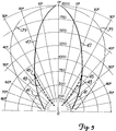
- Figure 5 is a diagram showing typical light beam dispersal patterns for an optical emitter of the prior art and two embodiments of the present invention.
- An optical traffic preemption detector within an emitter's dispersal pattern will be activated if the emitter is transmitting a valid optical signal.
- the range of an optical traffic preemption system is primarily dependent on the power of the optical emitter and the sensitivity of the detector.
- the dispersal patterns shown in Figure 5 are based on emitter/detector combinations that have an effective range of approximately 610m; a typical range for an optical traffic preemption system.
- the primary purpose of Figure 5 is to show the dispersal patterns of the present invention and prior art emitters, not the ranges of emitter/detector combinations.
- the line 39 represents a dispersal pattern for a typical optical emitter of the prior art. At a range of 380m, the arc of divergence of the beam is greater than 60 degrees, which results in beam that is greater than 460m wide at this range. Such a dispersal pattern is large enough to activate optical traffic preemption detector channels which are proximate to the traffic signals to be controlled, but are coupled to other traffic signal lights which are not to be controlled.
- the lines 41, 43 and 47 represent the dispersal patterns of two of the embodiments of the present invention.
- the line 41 represents the embodiment where the honeycomb element 40 has reflective surfaces and scatters light
- the line 43 represents the embodiment where the honeycomb element 40 is coated with a material which absorbs visible and infra-red light.
- the point 45 is where the optical characteristics of the two embodiments converge.
- the two embodiments have similar optical characteristics in the region represented by the line 47.
- both embodiments of the present invention have an arc of divergence of approximately 40 degrees, which results in a beam that is less than 260m wide at this range. Compared to optical emitters of the prior art, this narrow beam is much less likely to inadvertently activate an optical traffic preemption system detector channel which is proximate to the traffic signal lights to be controlled, but coupled to traffic signal lights which are not to be controlled.
- Figure 6 is an exploded view of an alternative embodiment in which the optical emitter assembly 20 is configured with an optional kit that allows the power supply board 32 and the timing board 34 to be mounted independently from the lamp 36, the reflector 38, the honeycomb element 40 and the front bezel 24.
- This optional kit is comprised of a housing cover 52, a cable 54 and a front bezel base 56, a bracket spacer 67, a mounting bracket 64 and some additional fasteners.
- the reflector 38, the lamp 36, the honeycomb element 40, the lens 42, the gasket 44 and the front bezel 24 are removed from the housing 22.
- the housing cover 52 is placed over the housing 22.
- the housing cover 52 is similar to the front bezel 24 and is joined with the housing 22 by inserting fasteners through the holes 60 to the threaded holes 28.
- a cable 54 which is secured to bracket spacer 67, couples the circuitry on the power supply board 32 and the timing board 34 to the lamp 36, which is housed in the front bezel base 56.
- the front bezel base 56 can be joined with the front bezel 24 by inserting fasteners through the holes 26 to the threaded holes 62.
- the emitter module 58 can be mounted on a vehicle by using the bracket 64.
- Emitter module 58 can also be mounted to an opening of a vehicle body, as shown in Figure 7 where emitter module 58 is mounted to a body 70 of a vehicle. In this mounting configuration, knock-out holes 66 (also shown in Figure 6) are opened so that fasteners 72 can attach the emitter assembly 58 to body 70.
- the supply module 68 can be mounted in a convenient location and connected to the emitter module 58 with cable 54.
Abstract
An optical signal emitter assembly (20) emits light pulses which are received by an optical traffic preemption system detector. The optical signal emitter assembly employs a honeycomb element (40) positioned in front of a light source (36) which collimates light emitted by the optical signal emitter assembly. The optical signal emitter assembly is convertible from a stand-alone unit containing power supply circuitry (32), timing circuitry (34), and a light source (36) in a single housing, to a unit wherein the light source can be mounted independently from a housing containing the power supply circuitry and the timing circuitry.
Description
- This invention relates to a system that allows authorized vehicles to remotely control traffic signals, and more specifically, to an optical signal emitter assembly for use in such a system, wherein an optical signal emitter assembly attached to an approaching authorized vehicle transmits a stream of light pulses to a detector mounted near a traffic intersection causing a preemption request to be issued to a traffic signal controller.
- Traffic signals have long been used to regulate the flow of traffic at intersections. Generally, traffic signals have relied on timers or vehicle sensors to determine when to change traffic signal lights, thereby signaling alternating directions of traffic to stop, and others to proceed.
- Emergency vehicles, such as police cars, fire trucks and ambulances, generally have the right to cross an intersection against a traffic signal. Emergency vehicles have typically depended on horns, sirens and flashing lights to alert other drivers approaching the intersection that an emergency vehicle intends to cross the intersection. However, due to hearing impairment, air conditioning, audio systems and other distractions, often the driver of a vehicle approaching an intersection will not be aware of a warning originating from an approaching emergency vehicle. This can create a dangerous situation when an emergency vehicle seeks to cross an intersection against a traffic signal and the driver of another vehicle approaching the intersection is not aware of the warning being transmitted by the emergency vehicle.
- This problem was first successfully addressed in U.S. Patent 3,550,078 (Long), which is assigned to the same assignee as the present application. The Long patent discloses an emergency vehicle with an optical emitter, a plurality of detectors mounted along an intersection with each detector looking down an approach to the intersection, a plurality of signal processing circuits located in the detectors which produce a signal representative of the distance of the approaching emergency vehicle, and a phase selector which processes the signal from the processing circuits and can issue a request to a traffic signal controller to preempt a normal traffic signal sequence and provide green lights to the approaching emergency vehicle.
- The Long patent discloses that as an emergency vehicle approaches an intersection, it emits a stream of light pulses at a predetermined rate, such as 10 pulses per second, and with each pulse having a duration of several microseconds. A detector receives the light pulses emitted by the approaching emergency vehicle. An output of the detector is processed by the phase selector, which then issues a request to a traffic signal controller to change to or hold green the traffic signal lights that control the emergency vehicle's approach to the intersection.
- This invention provides an optical signal emitter assembly for remote control use in an optical traffic preemption system. The invention comprises a housing, a light source for emitting light pulses, a power supply for converting a supply voltage into a power signal capable of activating the light source, and timing circuitry coupled to both the light source and the power supply, for controlling the repetition rate and duration of the light pulse. Also, a light collimating honeycomb element is positioned in front of the light source to collimate the light pulses, resulting in an optical signal which provides improved control of the traffic lights to be controlled. The optical emitter of the present invention is less likely to inadvertently activate an optical traffic preemption system detector channel proximate to the traffic signal lights to be controlled, but coupled to traffic signal lights which are not to be controlled.
- The invention is convertible from a stand-alone unit containing power supply circuitry, timing circuitry, and the light source in a single housing, to a unit wherein the light source can be mounted independently from a housing containing the power supply circuitry and the timing circuitry.
- Figure 1 is a perspective view of an intersection equipped with a traffic signal control system in which the optical emitter assembly of the present invention is mounted on an authorized vehicle approaching a typical traffic intersection.
- Figure 2 is an exploded view of the optical emitter assembly of Figure 1.
- Figure 3 is a front view of the optical emitter assembly of Figure 2.
- Figure 4 is a sectional view taken along line 4-4 of Figure 3 with portions thereof shown in full.
- Figure 5 is a diagram showing light beam dispersal patterns for an optical emitter of the prior art and two embodiments of the present invention.
- Figure 6 is an exploded view of an alternate embodiment of the optical emitter assembly of the present invention configured with an optional kit that allows parts of the assembly to be mounted in two separate housings.
- Figure 7 is a sectional view of a vehicle body showing an emitter module mounted through the vehicle body.
- Figure 1 is an illustration of a
typical intersection 10 withtraffic signal lights 12. Atraffic signal controller 14 sequences thetraffic signal lights 12 to allow traffic to proceed alternately through the intersection of particular relevance to the present invention, the intersection is equipped with an optical traffic preemption system, such as is commercially available under the trade designation "OPTICOM" Priority Control System manufactured by the Minnesota Mining and Manufacturing Company of Saint Paul, Minnesota. Such a system includesdetector assemblies 16 stationed to detect light pulses from optical emitter assemblies, one of which (20) is mounted on an authorized emergency vehicle 18, which is shown approaching theintersection 10 from a westbound direction. The detector assemblies 16 communicate with aphase selector 17, which is typically located in the same cabinet as thetraffic controller 14. - The
optical emitter assembly 20 transmits light pulses at a predetermined duration and repetition rate. Thedetector assembly 16 receives these light pulses and sends an output signal to thephase selector 17, which processes the signal and issues a request to thetraffic signal controller 14 to preempt a normal traffic signal sequence. If theoptical emitter assembly 20 emits light pulses at the predetermined repetition rate, with each pulse having sufficient intensity and fast enough rise time, thephase selector 17 will request thetraffic signal controller 14 to cause thetraffic signal lights 12 controlling the north, south and east bound directions to become or remain red and the traffic signal lights controlling the westbound direction to become or remain green. - The present invention makes several improvements over optical emitters of the prior art. The optical emitter assembly of the present invention is provided with a honeycomb element which collimates the emitted light into a generally non-divergent beam. A non-divergent beam is desirable because it can prevent an authorized vehicle from activating an optical traffic preemption system proximate to, but not coupled with the traffic signal lights to be controlled.
- Different embodiments of the honeycomb element can be employed. In one embodiment, the honeycomb element can have surfaces formed from a material which reflects light. In this embodiment, the honeycomb element tends to scatter light at close ranges, while having a collimating effect at longer ranges. This allows the emitter assembly to have a wide activation area when it is close to an optical traffic preemption system detector, yet have a narrow activation area when it is not close to a detector.
- In another embodiment, surfaces of the honeycomb element can be formed from a material which absorbs light, thereby preventing a scattering effect. In this embodiment, the honeycomb element only collimates the emitted light into a generally non-divergent beam.
- The present invention also provides more installation options than optical emitter assemblies of the prior art. The present invention is convertible from a stand-alone unit that has the power supply, timing circuitry and light source in the same housing into a two-piece unit having the power supply and timing circuitry within one housing and the light source, reflector, honeycomb element and lens within another housing. This allows a single design to be adapted to a wide variety of applications by allowing a user to purchase a simple kit, thereby reducing manufacturing costs and providing more flexibility to the user.
- Figure 2 is an exploded view of the
optical emitter assembly 20 of Figure 1. Theoptical emitter assembly 20 has ahousing 22 and afront bezel 24. Thefront bezel 24 can be joined with thehousing 22 by placing thefront bezel 24 over thehousing 22 and insertingfasteners 27 through theholes 26 to the threadedholes 28. Agasket 45 seals the interface between thehousing 22 and thefront bezel 24. - The
housing 22 has abracket 30, apower supply board 32 and atiming board 34. Thebracket 30 is used to mount theoptical emitter assembly 20 to a vehicle. Thepower supply board 32 receives a power supply voltage from the vehicle's power supply and converts the power supply voltage into a power signal, which is modulated by signals from thetiming board 34 to cause agaseous discharge lamp 36 to produce a stream of light pulses. - The
lamp 36 is positioned within areflector 38 that directs light through ahoneycomb element 40. Thereflector 38 has an opening above and below thelamp 36, providing ventilation to the area surrounding thelamp 36, thereby preventing thelamp 36 from overheating and damaging surrounding components. - The
honeycomb element 40, which is constructed of aluminum, collimates light into a beam that is generally non-divergent at distances over 150m. In one embodiment, the aluminum surfaces of thehoneycomb element 40 are exposed and reflect light so that at closer ranges, such as under 90m, theelement 40 tends to scatter light into a beam having an arc of divergence of approximately 160 degrees. - In another embodiment, the
honeycomb element 40 is coated with a visible and infra-red light absorbing material, such as black paint. In this embodiment, theelement 40 only collimates light into a beam which is generally non-divergent. It does not scatter light at closer ranges. - After light emitted by the
lamp 36 passes through thehoneycomb element 40, it passes through alens 42. In one embodiment, thelens 42 is constructed of a material that is transparent to infra-red and visible light. The preferred material for such a lens is a clear polycarbonate plastic, such as sold under the designation of "LEXAN 123," which is a product of the General Electric Company. - In another embodiment, the
lens 42 is constructed of a material which is opaque to visible light, but is transparent to infra-red light. The preferred material for such a lens is an acrylic plastic formed with a visible light blocking dye, such as Material No. V811 with Color No. 58189, manufactured by Rohm-Haas. In this embodiment, an observer watching an operatingoptical emitter assembly 20, will not be able to perceive that the emitter is in operation. An optical emitter assembly having alens 42 constructed of a material opaque to visible light and transparent to infra-red light will have a range that is approximately 25 to 50 percent less than the range of an optical emitter assembly having alens 42 constructed of material which is transparent to visible and infra-red light. -
Window 46 has the shape of a circle with the top and bottom of the circle truncated. In other embodiments,window 46 may assume other shapes, such as an oval or a rectangle. Agasket 44 is positioned between thelens 42 andfront bezel 24 to seal and weather-proof the assembly. Thegasket 44 has an opening similar in shape to that of thewindow 46 of thefront bezel 24. - Figure 3 is a front view of the
optical emitter assembly 20 and shows that thehoneycomb element 40 is constructed of a plurality ofcells 48. Each cell has an opening which extends from the front through to the rear of the cell and has a generally hexagonal shape with two sides equal to a first length and four sides equal to a second length. The first length is approximately 3.2 mm and the second length is approximately 4.8 mm. The longest distance across the opening of a cell is approximately 6.4 mm. These dimensions give the cells a somewhat horizontally squashed appearance. The preferred honeycomb material is manufactured by Hexcel Corporation and is available under part number ACG-1/4-4.8P. - Figure 4 is a sectional view taken along line 4-4 of Figure 3 with portions thereof shown in full. Figure 4 shows the orientation of the
honeycomb element 40 with respect to thelamp 36. When thelamp 36 emits light pulses, light coming directly from thelamp 36 and light reflected by thereflector 38 passes through thehoneycomb element 40. Thehoneycomb element 40 is approximately 9.5 mm thick and produces a light beam which is generally non-divergent at ranges greater than 150m. - In the embodiment where the
honeycomb element 40 has reflective surfaces, the interior surfaces of thecells 48 will scatter light at closer distances, resulting in a light beam having an arc of divergence of 160 degrees at ranges less than 90m. In the embodiment where thehoneycomb element 40 has surfaces which absorb visible and infra-red light, the light which passes through thehoneycomb element 40 is only collimated by thecells 48 and is not scattered. - Figure 4 also shows a
pulse transformer 37, which produces a high voltage output signal and is part of the emitter power supply. Thepulse transformer 37 is sensitive to heat and its high voltage output signal is difficult to transmit without causing electrical breakdown. For this reason, thepulse transformer 37 has been mounted to thefront bezel 24. This location is cooler than a location onpower supply board 32 and allows the high voltage output signal to be connected directly tolamp 36, thereby reducing the possibility of electrical breakdown. - Figure 5 is a diagram showing typical light beam dispersal patterns for an optical emitter of the prior art and two embodiments of the present invention. An optical traffic preemption detector within an emitter's dispersal pattern will be activated if the emitter is transmitting a valid optical signal.
- The range of an optical traffic preemption system is primarily dependent on the power of the optical emitter and the sensitivity of the detector. The dispersal patterns shown in Figure 5 are based on emitter/detector combinations that have an effective range of approximately 610m; a typical range for an optical traffic preemption system. The primary purpose of Figure 5 is to show the dispersal patterns of the present invention and prior art emitters, not the ranges of emitter/detector combinations.
- The
line 39 represents a dispersal pattern for a typical optical emitter of the prior art. At a range of 380m, the arc of divergence of the beam is greater than 60 degrees, which results in beam that is greater than 460m wide at this range. Such a dispersal pattern is large enough to activate optical traffic preemption detector channels which are proximate to the traffic signals to be controlled, but are coupled to other traffic signal lights which are not to be controlled. - The
lines line 41 represents the embodiment where thehoneycomb element 40 has reflective surfaces and scatters light, while theline 43 represents the embodiment where thehoneycomb element 40 is coated with a material which absorbs visible and infra-red light. Thepoint 45 is where the optical characteristics of the two embodiments converge. The two embodiments have similar optical characteristics in the region represented by theline 47. - At 380m, both embodiments of the present invention have an arc of divergence of approximately 40 degrees, which results in a beam that is less than 260m wide at this range. Compared to optical emitters of the prior art, this narrow beam is much less likely to inadvertently activate an optical traffic preemption system detector channel which is proximate to the traffic signal lights to be controlled, but coupled to traffic signal lights which are not to be controlled.
- Figure 6 is an exploded view of an alternative embodiment in which the
optical emitter assembly 20 is configured with an optional kit that allows thepower supply board 32 and thetiming board 34 to be mounted independently from thelamp 36, thereflector 38, thehoneycomb element 40 and thefront bezel 24. This optional kit is comprised of ahousing cover 52, acable 54 and afront bezel base 56, abracket spacer 67, a mounting bracket 64 and some additional fasteners. - To convert the stand-alone
optical emitter assembly 20 of Figure 2 into the two-part emitter assembly of Figure 6, which hasemitter module 58 andsupply module 68, thereflector 38, thelamp 36, thehoneycomb element 40, thelens 42, thegasket 44 and thefront bezel 24 are removed from thehousing 22. In place of thefront bezel 24, thehousing cover 52 is placed over thehousing 22. Thehousing cover 52 is similar to thefront bezel 24 and is joined with thehousing 22 by inserting fasteners through the holes 60 to the threaded holes 28. Acable 54, which is secured tobracket spacer 67, couples the circuitry on thepower supply board 32 and thetiming board 34 to thelamp 36, which is housed in thefront bezel base 56. Thefront bezel base 56 can be joined with thefront bezel 24 by inserting fasteners through theholes 26 to the threaded holes 62. Theemitter module 58 can be mounted on a vehicle by using the bracket 64. -
Emitter module 58 can also be mounted to an opening of a vehicle body, as shown in Figure 7 whereemitter module 58 is mounted to abody 70 of a vehicle. In this mounting configuration, knock-out holes 66 (also shown in Figure 6) are opened so thatfasteners 72 can attach theemitter assembly 58 tobody 70. Thesupply module 68 can be mounted in a convenient location and connected to theemitter module 58 withcable 54. - Although the present invention has been described with reference to preferred embodiments, workers skilled in the art will recognize that changes may be made in form and detail without departing from the spirit and scope of the invention.
Claims (10)
- An optical signal emitter assembly (20) for remotely controlling traffic signal lights and adapted to be affixed to an authorized vehicle, the optical emitter assembly comprising:
a housing (22);
a light source (36) for emitting light pulses;
a power supply (32) for converting a supply voltage into a power signal capable of activating the light source;
timing means (34) coupled to the power supply and the light source, for controlling the repetition rate and duration of light pulses;
collimating means (40) positioned in front of the light source, for collimating the light pulses emitted by the light source thereby resulting in a pulsed light beam capable of activating a first photodetector channel coupled to the traffic signal lights to be controlled, while not activating other photodetector channels proximate to the first photodetector channel, but coupled to other traffic signal lights which are not to be controlled. - The optical signal emitter assembly of claim 1 and further comprising a bezel (24) affixed to the front of said housing and containing both said collimating means and a lens (42) positioned in front of the collimating means (40).
- The optical signal emitter assembly of claim 1 wherein the collimating means is comprised of a honeycomb element having a plurality of cells, with each cell having an opening that extends from a front through to a rear of the cell.
- The optical signal emitter assembly of claim 3 characterized by the longest distance across the opening of a cell being approximately 6.4 mm and the distance between the front and the rear of a cell being approximately 9.5 mm, such that the resultant pulsed light beam is generally non-divergent at distances greater than 150 meters from the optical signal emitter assembly.
- The optical signal emitter assembly of claim 4 wherein surfaces of the honeycomb element are formed from a material which absorbs visible and infra-red light.
- The optical signal emitter assembly of claim 4 wherein surfaces of the honeycomb element are formed from a material which reflects visible and infra-red light, thereby scattering the light and resulting in the pulsed light beam having an arc of divergence of approximately 160 degrees at distances less than 90 meters from the optical signal emitter assembly.
- The optical signal emitter assembly of claim 1 wherein the power supply is positioned in the housing.
- The optical signal emitter assembly of claim 7 wherein heat sensitive components of the power supply are positioned in the bezel, and a remainder of power supply components are positioned in the housing.
- The optical signal emitter assembly of claim 1 and further comprising mounting means coupled to the housing for mounting the housing to a vehicle.
- The optical signal emitter assembly of claim 2 and further comprising:
conversion means for allowing the housing to be mounted separately from the bezel, the conversion means comprising:
a housing cover having third joining means, wherein the third joining means is joined with the first joining means; and
a bezel base having fourth joining means, wherein the second joining means is joined with the fourth joining means.
Applications Claiming Priority (2)
| Application Number | Priority Date | Filing Date | Title |
|---|---|---|---|
| US756321 | 1991-09-06 | ||
| US07/756,321 US5187373A (en) | 1991-09-06 | 1991-09-06 | Emitter assembly for use in an optical traffic preemption system |
Publications (1)
| Publication Number | Publication Date |
|---|---|
| EP0531045A1 true EP0531045A1 (en) | 1993-03-10 |
Family
ID=25042976
Family Applications (1)
| Application Number | Title | Priority Date | Filing Date |
|---|---|---|---|
| EP92307801A Withdrawn EP0531045A1 (en) | 1991-09-06 | 1992-08-27 | Optical signal emitter assembly |
Country Status (5)
| Country | Link |
|---|---|
| US (1) | US5187373A (en) |
| EP (1) | EP0531045A1 (en) |
| JP (1) | JPH05205195A (en) |
| AU (1) | AU663096B2 (en) |
| CA (1) | CA2075797C (en) |
Cited By (4)
| Publication number | Priority date | Publication date | Assignee | Title |
|---|---|---|---|---|
| US5747592A (en) * | 1994-12-16 | 1998-05-05 | Exxon Chemical Patents, Inc. | Thermoplastic polymer compositions and their production and use |
| US9711045B1 (en) | 2014-07-14 | 2017-07-18 | Tomar Electronics, Inc. | System and method for traffic preemption emitter type detection and response |
| WO2018219745A1 (en) | 2017-06-01 | 2018-12-06 | Philips Lighting Holding B.V. | A collimator device, a lighting device, a lamp and a luminaire |
| US11776389B2 (en) | 2021-01-19 | 2023-10-03 | Tomar Electronics, Inc. | Inter-vehicle optical network |
Families Citing this family (29)
| Publication number | Priority date | Publication date | Assignee | Title |
|---|---|---|---|---|
| JP3411924B2 (en) * | 1993-06-09 | 2003-06-03 | ミネソタ マイニング アンド マニュファクチャリング カンパニー | System for vehicle tracking |
| US6109767A (en) * | 1996-03-29 | 2000-08-29 | Minnesota Mining And Manufacturing Company | Honeycomb light and heat trap for projector |
| US5929787A (en) * | 1996-11-27 | 1999-07-27 | Mee; Gary L. | Vibration actuated traffic light control system |
| US6326903B1 (en) * | 2000-01-26 | 2001-12-04 | Dave Gross | Emergency vehicle traffic signal pre-emption and collision avoidance system |
| US7327280B2 (en) * | 2002-08-15 | 2008-02-05 | California Institute Of Technology | Emergency vehicle traffic signal preemption system |
| US7116245B1 (en) | 2002-11-08 | 2006-10-03 | California Institute Of Technology | Method and system for beacon/heading emergency vehicle intersection preemption |
| US20050264431A1 (en) * | 2002-04-09 | 2005-12-01 | Bachelder Aaron D | Forwarding system for long-range preemption and corridor clearance for emergency response |
| US7113108B1 (en) | 2002-04-09 | 2006-09-26 | California Institute Of Technology | Emergency vehicle control system traffic loop preemption |
| US7098806B2 (en) * | 2002-08-15 | 2006-08-29 | California Institute Of Technology | Traffic preemption system |
| JP4625697B2 (en) * | 2002-08-28 | 2011-02-02 | フィリップス ソリッド−ステート ライティング ソリューションズ インコーポレイテッド | Method and system for lighting an environment |
| US20050058413A1 (en) * | 2003-08-26 | 2005-03-17 | Poulsen Peter Davis | Light-absorbing surface and method |
| WO2005036494A2 (en) * | 2003-10-06 | 2005-04-21 | E-Views Safety Systems, Inc. | Detection and enforcement of failure-to-yield in an emergency vehicle preemption system |
| US20060017562A1 (en) * | 2004-07-20 | 2006-01-26 | Bachelder Aaron D | Distributed, roadside-based real-time ID recognition system and method |
| WO2006023841A2 (en) * | 2004-08-18 | 2006-03-02 | California Institute Of Technology | Roadside-based communication system and method |
| US7333028B2 (en) * | 2005-06-01 | 2008-02-19 | Global Traffic Technologies, Llc | Traffic preemption system communication method |
| US7417560B2 (en) * | 2005-06-01 | 2008-08-26 | Global Traffic Technologies, Llc | Multimode traffic priority/preemption intersection arrangement |
| US7573399B2 (en) * | 2005-06-01 | 2009-08-11 | Global Traffic Technologies, Llc | Multimode traffic priority/preemption vehicle arrangement |
| US7307547B2 (en) * | 2005-06-01 | 2007-12-11 | Global Traffic Technologies, Llc | Traffic preemption system signal validation method |
| US7432826B2 (en) * | 2005-06-16 | 2008-10-07 | Global Traffic Technologies, Llc | Traffic preemption system with headway management |
| US7515064B2 (en) * | 2005-06-16 | 2009-04-07 | Global Traffic Technologies, Llc | Remote activation of a vehicle priority system |
| US20070014119A1 (en) * | 2005-07-12 | 2007-01-18 | Burkett Karl A | Variable lighting system for optimizing night visibility |
| US8823548B2 (en) * | 2010-06-15 | 2014-09-02 | Global Traffic Technologies, Llc | Control of traffic signal phases |
| US20130049985A1 (en) * | 2011-08-24 | 2013-02-28 | Henry Eisenson | Device and system to alert vehicles and pedestrians of approaching emergency vehicles and emergency situations |
| US10068471B2 (en) | 2015-12-21 | 2018-09-04 | Collision Control Communications, Inc. | Collision avoidance and traffic signal preemption system |
| US10078962B1 (en) | 2017-04-28 | 2018-09-18 | International Business Machines Corporation | Identification and control of traffic at one or more traffic junctions |
| US11069234B1 (en) | 2018-02-09 | 2021-07-20 | Applied Information, Inc. | Systems, methods, and devices for communication between traffic controller systems and mobile transmitters and receivers |
| US11205345B1 (en) | 2018-10-02 | 2021-12-21 | Applied Information, Inc. | Systems, methods, devices, and apparatuses for intelligent traffic signaling |
| WO2020198873A1 (en) * | 2019-04-03 | 2020-10-08 | Logisig Inc. | Electrical cabinets |
| US11899468B2 (en) * | 2020-12-22 | 2024-02-13 | Waymo Llc | Sensor for flashing light detection |
Citations (4)
| Publication number | Priority date | Publication date | Assignee | Title |
|---|---|---|---|---|
| DE748653C (en) * | 1933-01-25 | 1944-11-06 | Remote control device with transmission of the control commands by a light beam | |
| GB1001394A (en) * | 1963-11-15 | 1965-08-18 | Arthur Whitson Neaville | Remote control system for automotive vehicles |
| US3550078A (en) * | 1967-03-16 | 1970-12-22 | Minnesota Mining & Mfg | Traffic signal remote control system |
| DE2733937A1 (en) * | 1977-07-27 | 1979-02-08 | Siemens Ag | Optical coloured signal generator - has LED located within profiled lens for improved focussing of emergent rays |
Family Cites Families (10)
| Publication number | Priority date | Publication date | Assignee | Title |
|---|---|---|---|---|
| US3739179A (en) * | 1971-01-07 | 1973-06-12 | I Krekow | Radiation sensitive traffic warning system |
| USRE28100E (en) * | 1973-07-13 | 1974-08-06 | Traffic signal remote control system | |
| US4162477A (en) * | 1977-06-03 | 1979-07-24 | Minnesota Mining And Manufacturing Company | Remote control system for traffic signal control system |
| US4223295A (en) * | 1978-10-18 | 1980-09-16 | Nelson A. Faerber | Emergency control system for traffic signals |
| US4234967A (en) * | 1978-10-20 | 1980-11-18 | Minnesota Mining And Manufacturing Company | Optical signal transmitter |
| US4240063A (en) * | 1979-07-23 | 1980-12-16 | Indicator Controls Corp. | Visor assembly for pedestrian traffic signal |
| US4435696A (en) * | 1981-09-25 | 1984-03-06 | Indicator Controls Corporation | Visor assembly for pedestrian traffic signal |
| US4662726A (en) * | 1983-12-01 | 1987-05-05 | Sanders Associates, Inc. | Reflective optical element |
| US4704610A (en) * | 1985-12-16 | 1987-11-03 | Smith Michel R | Emergency vehicle warning and traffic control system |
| US4942503A (en) * | 1989-04-28 | 1990-07-17 | Minnesota Mining And Manufacturing Company | Gaseous discharge tube and power supply assembly |
-
1991
- 1991-09-06 US US07/756,321 patent/US5187373A/en not_active Expired - Lifetime
-
1992
- 1992-08-11 CA CA002075797A patent/CA2075797C/en not_active Expired - Lifetime
- 1992-08-12 AU AU21001/92A patent/AU663096B2/en not_active Ceased
- 1992-08-27 EP EP92307801A patent/EP0531045A1/en not_active Withdrawn
- 1992-09-07 JP JP4238118A patent/JPH05205195A/en active Pending
Patent Citations (4)
| Publication number | Priority date | Publication date | Assignee | Title |
|---|---|---|---|---|
| DE748653C (en) * | 1933-01-25 | 1944-11-06 | Remote control device with transmission of the control commands by a light beam | |
| GB1001394A (en) * | 1963-11-15 | 1965-08-18 | Arthur Whitson Neaville | Remote control system for automotive vehicles |
| US3550078A (en) * | 1967-03-16 | 1970-12-22 | Minnesota Mining & Mfg | Traffic signal remote control system |
| DE2733937A1 (en) * | 1977-07-27 | 1979-02-08 | Siemens Ag | Optical coloured signal generator - has LED located within profiled lens for improved focussing of emergent rays |
Non-Patent Citations (1)
| Title |
|---|
| PATENT ABSTRACTS OF JAPAN vol. 7, no. 125 (P-200)31 May 1983 & JP-A-58 042 986 ( HITACHI DENSEN KK ) 12 March 1983 * |
Cited By (7)
| Publication number | Priority date | Publication date | Assignee | Title |
|---|---|---|---|---|
| US5747592A (en) * | 1994-12-16 | 1998-05-05 | Exxon Chemical Patents, Inc. | Thermoplastic polymer compositions and their production and use |
| US9711045B1 (en) | 2014-07-14 | 2017-07-18 | Tomar Electronics, Inc. | System and method for traffic preemption emitter type detection and response |
| WO2018219745A1 (en) | 2017-06-01 | 2018-12-06 | Philips Lighting Holding B.V. | A collimator device, a lighting device, a lamp and a luminaire |
| CN110678796A (en) * | 2017-06-01 | 2020-01-10 | 昕诺飞控股有限公司 | Collimator device, lighting device, lamp and luminaire |
| US11143386B2 (en) | 2017-06-01 | 2021-10-12 | Signify Holding B.V. | Collimator device, a lighting device, a lamp and a luminaire |
| CN110678796B (en) * | 2017-06-01 | 2022-05-24 | 昕诺飞控股有限公司 | Collimator device, lighting device, lamp and luminaire |
| US11776389B2 (en) | 2021-01-19 | 2023-10-03 | Tomar Electronics, Inc. | Inter-vehicle optical network |
Also Published As
| Publication number | Publication date |
|---|---|
| AU2100192A (en) | 1993-03-11 |
| JPH05205195A (en) | 1993-08-13 |
| AU663096B2 (en) | 1995-09-28 |
| CA2075797C (en) | 2002-10-08 |
| US5187373A (en) | 1993-02-16 |
| CA2075797A1 (en) | 1993-03-07 |
Similar Documents
| Publication | Publication Date | Title |
|---|---|---|
| US5187373A (en) | Emitter assembly for use in an optical traffic preemption system | |
| US6558026B2 (en) | Lamp masking method and apparatus | |
| US5097397A (en) | Non-linear signalling device for vehicles | |
| US8182125B2 (en) | External safety illumination for a bus with light mounted to mirror arm | |
| US6550943B2 (en) | Lamp masking method and apparatus | |
| US5373426A (en) | Front-mounted vehicle brake light | |
| US6142656A (en) | Multi-functional side rear view mirror for a vehicle | |
| US6286983B1 (en) | Mirror having an illuminated film for signaling and general illumination | |
| US4631516A (en) | Auxiliary vehicle warning system | |
| US5225827A (en) | Warning device in a motor vehicle for detection of unintentional change of course | |
| US6072391A (en) | Information indicator for vehicle | |
| US3875561A (en) | Flashing vehicle warning beacon with lens and reflector | |
| US20020014975A1 (en) | Rearview mirror assembly with integral display element | |
| GB2311265A (en) | Vehicle blind spot detection and display system | |
| US5541891A (en) | Distance sensing device | |
| US9611993B2 (en) | Warning light with tinted lens | |
| US20200361370A1 (en) | Vehicle visual signaling device | |
| US7036966B2 (en) | Lamp masking method and apparatus | |
| US3919543A (en) | Emergency light | |
| US4047020A (en) | Disguised emergency light | |
| CN108386815B (en) | Automobile tail lamp and vehicle with same | |
| JP2013177017A (en) | Impact-warning and prevention device | |
| US5984496A (en) | Lighted mirror assembly | |
| JPH1021499A (en) | Abnormal approach warning display device | |
| EP0499081B1 (en) | Stop light for vehicle |
Legal Events
| Date | Code | Title | Description |
|---|---|---|---|
| PUAI | Public reference made under article 153(3) epc to a published international application that has entered the european phase |
Free format text: ORIGINAL CODE: 0009012 |
|
| AK | Designated contracting states |
Kind code of ref document: A1 Designated state(s): DE ES FR GB IT NL |
|
| 17P | Request for examination filed |
Effective date: 19930609 |
|
| 17Q | First examination report despatched |
Effective date: 19950822 |
|
| STAA | Information on the status of an ep patent application or granted ep patent |
Free format text: STATUS: THE APPLICATION IS DEEMED TO BE WITHDRAWN |
|
| 18D | Application deemed to be withdrawn |
Effective date: 19960503 |