EP0531036B1 - Injector for hypodermically implanting an object in a living being - Google Patents
Injector for hypodermically implanting an object in a living being Download PDFInfo
- Publication number
- EP0531036B1 EP0531036B1 EP92307746A EP92307746A EP0531036B1 EP 0531036 B1 EP0531036 B1 EP 0531036B1 EP 92307746 A EP92307746 A EP 92307746A EP 92307746 A EP92307746 A EP 92307746A EP 0531036 B1 EP0531036 B1 EP 0531036B1
- Authority
- EP
- European Patent Office
- Prior art keywords
- needle
- housing
- push rod
- needleholder
- living
- Prior art date
- Legal status (The legal status is an assumption and is not a legal conclusion. Google has not performed a legal analysis and makes no representation as to the accuracy of the status listed.)
- Expired - Lifetime
Links
Images


Classifications
-
- A—HUMAN NECESSITIES
- A61—MEDICAL OR VETERINARY SCIENCE; HYGIENE
- A61M—DEVICES FOR INTRODUCING MEDIA INTO, OR ONTO, THE BODY; DEVICES FOR TRANSDUCING BODY MEDIA OR FOR TAKING MEDIA FROM THE BODY; DEVICES FOR PRODUCING OR ENDING SLEEP OR STUPOR
- A61M37/00—Other apparatus for introducing media into the body; Percutany, i.e. introducing medicines into the body by diffusion through the skin
- A61M37/0069—Devices for implanting pellets, e.g. markers or solid medicaments
Definitions
- the invention relates to an injector as defined in the precharacterizing part of claim 1.
- Such an injector is known from NL-A-8,902,283.
- the spring force necessary for the various actions is produced in it by means of a tensioning handle.
- the needle in this case is situated in the housing when in the storage position.
- the unlocking means are thereby operated.
- Said unlocking means release the control means.
- These control means are a puller. By means of said puller, a spring-loaded slide is released, so that the needle shoots into the animal. This means that the user does not see the insertion movement of the needle into the animal, because the injector is always held against the animal. Disconnection of the needle and the slide takes place at the end of the movement of the needle into the animal.
- Another disadvantage of this device is that, if it is in the tensioned state, the needle is present under spring tension in the housing. It is extremely simple for unskilled people, and in particular children, to injure themselves by pressing the unlocking means when engaging the control means.
- injectors are meant in particular to be used by non-medical people such as farmers, it is important that they have a good view as regards the positioning of the needle. It is therefore important that they can see accurately how the needle is placed and how it enters the living being.
- an injector for hypodermically implanting drug-containing pellets in animals comprises a housing accomodating a needle and a needle-holder in such a way that the needle is slidable out of said housing, on which needle a spring acts, said spring being tensioned during the outward movement of the needle, with a push rod fitted in said hollow needle for conveyance of said object, with unlocking means fitted on the housing and with control means for moving the needle out of the housing, wherein the control means are connected to the needle and needle holder and pretension the spring and lock the needle in the extended position before insertion of the object into the living being, and the unlocking means unlocks the needle for returning it to the housing.
- the object of the present invention is to avoid the disadvantages of the above injectors.
- the invention is based on the idea of moving the needle out with the control means before injecting. For this, two hands are needed, one hand to hold the housing, and the other hand to move the control means. This limits the risk of injuries. Only when the needle has been moved out are the unlocking means brought into play and without further action, i.e. without the intervention of further control means, the needle will be moved back when the skin acts on the unlocking means. Since the needle has already been moved out for the injection, it is necessary for the person inserting the object to place the needle together with the injector in the animal with his own force. This means that very accurate and readily visible positioning of the needle and insertion of the needle are possible, on the one hand, while "feeling" for insertion of the needle in the animal is present, on the other.
- the unlocking means will touch the skin of the living being in question, and the needle will move back, with the result that a safe situation is immediately obtained, so that it is no longer possible for undesirable injuries to take place.
- the needle is provided so that it is lockable on the needleholder in a simple manner using a push button.
- the object to be implanted is inserted into a nesting place in the housing.
- both the needle and the push rod move into the living being, i.e. in a stationary position relative to the housing the hollow needle accommodates the object, and the object is then conveyed by the push rod situated inside the needle.
- the unlocking means act on the rear side of the push rod. Blocking devices are present here to lock the needle in the position where it is moved out. By means of a stop fitted on the push rod, said blocking devices can be unlocked, so that the needle together with the push rod can be moved back.
- the movement in this case takes place in such a way that on operation of the unlocking means the push rod is first moved out with the object, and at the end of the movement path of the push rod through releasing of the blocking devices the needle is moved back together with the push rod, leaving behind the object in position in the animal.
- the nesting place houses a number of objects, and means for placing these in succession in front of the push rod in the hollow needle.
- the objects such as transponders
- cartridges can always automatically be moved one position further through acting upon the control means.
- such cartridges can have cavities filled with liquid or ointment, in which the relevant objects are placed.
- the hollow needle or the push rod in this case easily pierces the ends of the cartridge to be pierced.
- Fig. 1 shows in side view a so-called multi-shot injector. It is indicated in its entirety by 1, and comprises a housing 13 from which projects a control handle 15 which is guided slidably. At the top side of housing 1 a nesting place 17 is present for placing therein a cartridge 30 in which objects 14 to be implanted are accommodated. The position of cartridge 30 with object 14 in it can be observed through inspection window 18. An unlocking catch 6 and also an extended needle 3 are shown at the front side of housing 13.
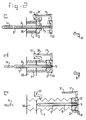
- Figs. 2a - 2e show schematically the mechanism situated in housing 13.
- a slidable needle 3 fixed in a needleholder 2 is present.
- a compression spring 4 acts on needleholder 2 and at the other side acts on the housing.
- a push rod 9 is present for moving objects 14.
- Push rod 9 is at one end provided with a push rod plate 10 on which a tension spring 5 acts, which spring is connected at the other side to the needleholder 2.
- Acting on push rod plate 10 is an unlocking lever 8 which is connected by means of an unlocking rod 7 to unlocking catch 6.
- Push rod plate 10 is also provided with a stop 11.
- a blocking device 12 which can act on needleholder 2 is fitted on the housing 1.
- injector 1 In the stored position, injector 1 is in the position shown in Fig. 2a, i.e. needle 3 is inside housing 13, so that any risk of accidental injuries is avoided.
- Cartridge 30 is provided in order to inject an object 14 into a living being.
- Through inspection window 18 an optical indication is obtained of whether an object 14 is in fact lying in front of needle 3 (Fig. 2a).
- the operation of the unlocking catch 6 In the position shown in Fig. 2a the operation of the unlocking catch 6 has no effect at all.
- both springs 4 and 5 are in their untensioned position in Fig. 2a.
- the device is then made ready for the injection of an object 14.
- the springs 4 and 5 are tensioned by moving control handle 15 to the left out of the position shown in Fig. 2a. Needle 3 will in the process move outwards, and push rod 9 will be held in place through push rod plate 10 being held by unlocking lever 8. After the movement of needleholder 2 along blocking device 12, it can no longer move back by itself. The situation shown in Fig. 2b is reached before the placing of the injector on the animal. For such an operation two hands are needed, one hand to hold the housing 13, and the other hand to move the control handle 15 to the left. In this way injuries from the sharp hollow needle are prevented as far as possible. When needle 3 is moved to the left the cartridge in which object 14 is situated is pierced.
- the injector is then moved near an animal, and needle 3 is placed in the animal. All this takes place with manual force, so that the operating person can see and feel well how the needle goes into the animal in question.
- unlocking catch 6 is operated through contact with the animal.
- unlocking lever 8 tilts, so that push rod plate 10 and the push rod are released.
- push rod 9 slides to the position shown in Fig. 2c, in which the object to be injected, such as a transponder, is moved to the end of the needle.
- this movement of push rod 9 is continued until stop 11 touches blocking device 12. Further movement to the left is not possible.
- the end position is shown by dashed lines in Fig. 2c. Stop 11 is provided near the end with a softer part 31, in order to make the impact of stop 11 against blocking device 12 take place somewhat gradually.
- Releasing blocking device 12 causes needleholder 2 to move to the right. This movement is produced by spring 4.
- Spring 5 still tries to bring push rod plate 10 and needleholder 2 as close together as possible.
- the object 14, such as a transponder can never be pushed out of the needle by the push rod 9.
- the needle is withdrawn to the position shown in Fig. 2d, and the push rod 9 remains stationary, with the result that the transponder stays in place, and the needle is moved back. Placing in this way ensures that, on the one hand, tissue damage is avoided and, on the other, damage to the object to be placed is prevented.
- Fig. 3 the fixing of the needle 3 on the needleholder 2 is shown. It can be seen that a push button 16 with a lever mechanism 33 is present. The lobe of the lever in this case falls into a recess 34 provided in the needle. A needle can be removed simply from holder 2 by operating button 16.
Landscapes
- Health & Medical Sciences (AREA)
- Engineering & Computer Science (AREA)
- Life Sciences & Earth Sciences (AREA)
- Animal Behavior & Ethology (AREA)
- Anesthesiology (AREA)
- Biomedical Technology (AREA)
- Heart & Thoracic Surgery (AREA)
- Hematology (AREA)
- Dermatology (AREA)
- Medical Informatics (AREA)
- General Health & Medical Sciences (AREA)
- Public Health (AREA)
- Veterinary Medicine (AREA)
- Infusion, Injection, And Reservoir Apparatuses (AREA)
- Prostheses (AREA)
- Media Introduction/Drainage Providing Device (AREA)
Abstract
Description
- The invention relates to an injector as defined in the precharacterizing part of
claim 1. - Such an injector is known from NL-A-8,902,283. The spring force necessary for the various actions is produced in it by means of a tensioning handle. The needle in this case is situated in the housing when in the storage position. For the implantation of an object, the injector is moved against the animal with the needle fitted in the housing. The unlocking means are thereby operated. Said unlocking means release the control means. These control means are a puller. By means of said puller, a spring-loaded slide is released, so that the needle shoots into the animal. This means that the user does not see the insertion movement of the needle into the animal, because the injector is always held against the animal. Disconnection of the needle and the slide takes place at the end of the movement of the needle into the animal. This means that the needle is moved back out of the animal, with the slide remaining in the same position. A push rod which does not make such a return movement is also connected to the slide. Due to the fact that during the implantation an object to be implanted, such as a transponder, is placed in front of the push rod, when the needle is withdrawn and the push rod remains in place, such a transponder will be placed in the animal.
- A number of disadvantages are associated with the use of this device. For tensioning of the injector, energy must be supplied both for the withdrawal of the needle and for the insertion of the needle. For, only a blocking is released by the control means. The energy required in particular during insertion of the needle is very variable. One skin is easier to pierce than another skin, due to greater thickness or other circumstances, while the state of the tissue under the skin can vary widely. This means that, either a very great pre-tensioning force is needed, which on relatively easy penetration causes too great a shock and could damage the object to be implanted, or not enough force is used to ensure that the needle penetrates sufficiently into the animal in all circumstances. If there is inadequate penetration into the animal, the placing of the transponder can go completely wrong.
- Another disadvantage of this device is that, if it is in the tensioned state, the needle is present under spring tension in the housing. It is extremely simple for unskilled people, and in particular children, to injure themselves by pressing the unlocking means when engaging the control means.
- Since such injectors are meant in particular to be used by non-medical people such as farmers, it is important that they have a good view as regards the positioning of the needle. It is therefore important that they can see accurately how the needle is placed and how it enters the living being.
- In US-A-4 105 030 an injector for hypodermically implanting drug-containing pellets in animals is disclosed. This injector comprises a housing accomodating a needle and a needle-holder in such a way that the needle is slidable out of said housing, on which needle a spring acts, said spring being tensioned during the outward movement of the needle, with a push rod fitted in said hollow needle for conveyance of said object, with unlocking means fitted on the housing and with control means for moving the needle out of the housing, wherein the control means are connected to the needle and needle holder and pretension the spring and lock the needle in the extended position before insertion of the object into the living being, and the unlocking means unlocks the needle for returning it to the housing.
- The object of the present invention is to avoid the disadvantages of the above injectors.
- This object is achieved in the case of the device described above by the features of the characterizing part of
claim 1. - The invention is based on the idea of moving the needle out with the control means before injecting. For this, two hands are needed, one hand to hold the housing, and the other hand to move the control means. This limits the risk of injuries. Only when the needle has been moved out are the unlocking means brought into play and without further action, i.e. without the intervention of further control means, the needle will be moved back when the skin acts on the unlocking means. Since the needle has already been moved out for the injection, it is necessary for the person inserting the object to place the needle together with the injector in the animal with his own force. This means that very accurate and readily visible positioning of the needle and insertion of the needle are possible, on the one hand, while "feeling" for insertion of the needle in the animal is present, on the other. There are no longer problems with regard to encountering obstacles or easier insertion of the needle in certain cases, while damage to the object to be implanted is prevented. Since the energy for insertion of the needle is produced by pressure on the injector, the spring construction can be made lighter, and less tensioning force is required.
- The moment the insertion is completed, the unlocking means will touch the skin of the living being in question, and the needle will move back, with the result that a safe situation is immediately obtained, so that it is no longer possible for undesirable injuries to take place.
- According to the invention, the needle is provided so that it is lockable on the needleholder in a simple manner using a push button.
- According to the invention the object to be implanted is inserted into a nesting place in the housing. In this case both the needle and the push rod move into the living being, i.e. in a stationary position relative to the housing the hollow needle accommodates the object, and the object is then conveyed by the push rod situated inside the needle. In this embodiment, the unlocking means act on the rear side of the push rod. Blocking devices are present here to lock the needle in the position where it is moved out. By means of a stop fitted on the push rod, said blocking devices can be unlocked, so that the needle together with the push rod can be moved back. The movement in this case takes place in such a way that on operation of the unlocking means the push rod is first moved out with the object, and at the end of the movement path of the push rod through releasing of the blocking devices the needle is moved back together with the push rod, leaving behind the object in position in the animal. According to a special embodiment, provision is made here for the push rod at the end of the movement to position the object near the front end of the needle, so that the object is not pressed into the living being, but the object is placed only by moving back the needle and holding the push rod still during a short stage of the return movement.
- According to an advantageous embodiment, the nesting place houses a number of objects, and means for placing these in succession in front of the push rod in the hollow needle. This means that the objects, such as transponders, can be supplied in cartridges, and that cartridges can always automatically be moved one position further through acting upon the control means. As is generally known in the state of the art, such cartridges can have cavities filled with liquid or ointment, in which the relevant objects are placed. The hollow needle or the push rod in this case easily pierces the ends of the cartridge to be pierced.
- The invention will be explained in greater detail below with reference to examples of embodiments shown in the drawing, in which:
- Fig. 1 shows a side view of a first embodiment of the injector according to the invention;
- Figs. 2a-2e show schematically the displacement mechanism for the hollow needle and the push rod in various positions, which displacement mechanism is fitted in the injector according to Fig. 1;
- Fig. 3 shows the fixing mechanism of the hollow needle to the needleholder; and
- Fig. 1 shows in side view a so-called multi-shot injector. It is indicated in its entirety by 1, and comprises a
housing 13 from which projects acontrol handle 15 which is guided slidably. At the top side of housing 1 anesting place 17 is present for placing therein acartridge 30 in whichobjects 14 to be implanted are accommodated. The position ofcartridge 30 withobject 14 in it can be observed throughinspection window 18. Anunlocking catch 6 and also an extendedneedle 3 are shown at the front side ofhousing 13. - Figs. 2a - 2e show schematically the mechanism situated in
housing 13. As already indicated above, aslidable needle 3 fixed in aneedleholder 2 is present. Acompression spring 4 acts onneedleholder 2 and at the other side acts on the housing. Apush rod 9 is present formoving objects 14. Pushrod 9 is at one end provided with apush rod plate 10 on which atension spring 5 acts, which spring is connected at the other side to theneedleholder 2. Acting onpush rod plate 10 is an unlockinglever 8 which is connected by means of an unlocking rod 7 to unlockingcatch 6. Pushrod plate 10 is also provided with astop 11. A blockingdevice 12 which can act onneedleholder 2 is fitted on thehousing 1. - The device described above works as follows:
- In the stored position,
injector 1 is in the position shown in Fig. 2a, i.e.needle 3 is insidehousing 13, so that any risk of accidental injuries is avoided.Cartridge 30 is provided in order to inject anobject 14 into a living being. Throughinspection window 18 an optical indication is obtained of whether anobject 14 is in fact lying in front of needle 3 (Fig. 2a). In the position shown in Fig. 2a the operation of the unlockingcatch 6 has no effect at all. For, bothsprings - The device is then made ready for the injection of an
object 14. For this, thesprings Needle 3 will in the process move outwards, and pushrod 9 will be held in place throughpush rod plate 10 being held by unlockinglever 8. After the movement ofneedleholder 2 along blockingdevice 12, it can no longer move back by itself. The situation shown in Fig. 2b is reached before the placing of the injector on the animal. For such an operation two hands are needed, one hand to hold thehousing 13, and the other hand to move the control handle 15 to the left. In this way injuries from the sharp hollow needle are prevented as far as possible. Whenneedle 3 is moved to the left the cartridge in which object 14 is situated is pierced. - The injector is then moved near an animal, and
needle 3 is placed in the animal. All this takes place with manual force, so that the operating person can see and feel well how the needle goes into the animal in question. At the end of insertion of the needle into the animal, unlockingcatch 6 is operated through contact with the animal. As shown by dashed lines in Fig. 2b, unlockinglever 8 tilts, so thatpush rod plate 10 and the push rod are released. This causespush rod 9 to slide to the position shown in Fig. 2c, in which the object to be injected, such as a transponder, is moved to the end of the needle. As can be seen from Fig. 2c, this movement ofpush rod 9 is continued untilstop 11touches blocking device 12. Further movement to the left is not possible. The end position is shown by dashed lines in Fig. 2c.Stop 11 is provided near the end with asofter part 31, in order to make the impact ofstop 11 against blockingdevice 12 take place somewhat gradually. - Releasing blocking
device 12 causes needleholder 2 to move to the right. This movement is produced byspring 4.Spring 5 still tries to bringpush rod plate 10 andneedleholder 2 as close together as possible. The result of this is that theobject 14, such as a transponder, can never be pushed out of the needle by thepush rod 9. Starting from the position shown in Fig. 2c, the needle is withdrawn to the position shown in Fig. 2d, and thepush rod 9 remains stationary, with the result that the transponder stays in place, and the needle is moved back. Placing in this way ensures that, on the one hand, tissue damage is avoided and, on the other, damage to the object to be placed is prevented. As shown in Fig. 2d, the needle together with the push rod then moves to the right to the position shown in Fig. 2e, where both parts are safely accommodated in the housing. At the end of this movement or at the beginning of the operation with the aid of control handle 15, a further conveyance mechanism (not shown) can be operated to makecartridge 30 slide one position further. - In Fig. 3 the fixing of the
needle 3 on theneedleholder 2 is shown. It can be seen that apush button 16 with alever mechanism 33 is present. The lobe of the lever in this case falls into arecess 34 provided in the needle. A needle can be removed simply fromholder 2 by operatingbutton 16.
Claims (5)
- Injector (1) for hypodermically implanting an object (14) into a living being, comprising a housing (13) accommodating a needle (3) in such a way that it is slidable out of said housing and connected to a needleholder (2), on which said needleholder (2) a spring (4) acts, said spring being tensioned during the outward movement of the needle, with a push rod (9) fitted in said hollow needle for conveyance of said object, with unlocking means (6, 7, 8) fitted on the housing, and with control means (15) which move the needle out of the housing, and wherein the control means are connected to the needleholder (2) and pre-tension the spring (4) and lock the needle in the extended position before insertion of the object into the living being, and the unlocking means (6, 7, 8) unlock the needle (3) for returning it to the housing (13) characterized in that- said unlocking means are fitted near the aperture of the needle, and located at least partially outside of the housing for detecting the contact with the living being and unlocking the needle (3) upon detection of the contact with the living being, and- the push rod (9) is movable relative to the housing (13), and is provided with a push rod plate (10) on which the spring (5) and said unlocking means (6, 7, 8) act, and the housing is provided with a nesting place (17) for objects to be injected.
- Device according to Claim 1, in which the needle (3) is fixed to the needleholder (2) by means of a securing device operated by a push button (16).
- Device according to Claim 1 or Claim 2, in which blocking devices (12) maintain pre-tension of said spring (4) between the push rod plate (10) and the needleholder (2) while the needle is in the extended position, and the push rod plate (10) provides stop means (11) which release the blocking devices at the end of the movement thereof upon triggering of said unlocking means (6, 7, 8), thereby moving said needle back into said housing.
- Device according to Claim 1, 2, or 3, characterized in that the needleholder (2), upon release from said blocking devices (12), covers a distance which corresponds to the length of the object to be placed before taking along the push rod.
- Device according to any of the preceding Claims, in which the nesting place (17) houses a number of objects, and means place them in succession in the hollow needle before the push rod.
Applications Claiming Priority (2)
| Application Number | Priority Date | Filing Date | Title |
|---|---|---|---|
| NL9101489 | 1991-09-03 | ||
| NL9101489A NL9101489A (en) | 1991-09-03 | 1991-09-03 | INJECTOR FOR IMMEDIATELY IMPLANTING AN OBJECT IN A LIVING BEING. |
Publications (2)
| Publication Number | Publication Date |
|---|---|
| EP0531036A1 EP0531036A1 (en) | 1993-03-10 |
| EP0531036B1 true EP0531036B1 (en) | 1997-11-19 |
Family
ID=19859663
Family Applications (1)
| Application Number | Title | Priority Date | Filing Date |
|---|---|---|---|
| EP92307746A Expired - Lifetime EP0531036B1 (en) | 1991-09-03 | 1992-08-25 | Injector for hypodermically implanting an object in a living being |
Country Status (6)
| Country | Link |
|---|---|
| US (1) | US5273532A (en) |
| EP (1) | EP0531036B1 (en) |
| AT (1) | ATE160289T1 (en) |
| AU (1) | AU653243B2 (en) |
| DE (1) | DE69223200T2 (en) |
| NL (1) | NL9101489A (en) |
Families Citing this family (92)
| Publication number | Priority date | Publication date | Assignee | Title |
|---|---|---|---|---|
| CA2135706C (en) * | 1993-11-15 | 1999-06-15 | Walter E. Cover | Retractable-needle cannula insertion set with refinements to better control leakage, retraction speed, and reuse |
| US5542920A (en) * | 1994-09-12 | 1996-08-06 | Delab | Needle-less parenteral introduction device |
| US6530896B1 (en) | 1996-05-13 | 2003-03-11 | James B. Elliott | Apparatus and method for introducing an implant |
| US5827293A (en) * | 1996-05-13 | 1998-10-27 | Elliott; James B. | Subcutaneous insertion device |
| GB9703166D0 (en) * | 1997-02-15 | 1997-04-02 | Sterimatic Holdings Ltd | Improvements in or relating to implanters |
| DE19734385C1 (en) * | 1997-08-08 | 1999-02-18 | Gaplast Gmbh | Implant syringe |
| US7637948B2 (en) * | 1997-10-10 | 2009-12-29 | Senorx, Inc. | Tissue marking implant |
| US8668737B2 (en) | 1997-10-10 | 2014-03-11 | Senorx, Inc. | Tissue marking implant |
| US6007474A (en) * | 1997-10-20 | 1999-12-28 | Ablation Technologies, Inc. | Radioactive and/or thermal seed implantation device |
| US6161034A (en) * | 1999-02-02 | 2000-12-12 | Senorx, Inc. | Methods and chemical preparations for time-limited marking of biopsy sites |
| US7063681B1 (en) * | 1998-04-23 | 2006-06-20 | Alza Corporation | Trocar for inserting implants |
| US6725083B1 (en) | 1999-02-02 | 2004-04-20 | Senorx, Inc. | Tissue site markers for in VIVO imaging |
| US7651505B2 (en) * | 2002-06-17 | 2010-01-26 | Senorx, Inc. | Plugged tip delivery for marker placement |
| US8498693B2 (en) | 1999-02-02 | 2013-07-30 | Senorx, Inc. | Intracorporeal marker and marker delivery device |
| US20090030309A1 (en) | 2007-07-26 | 2009-01-29 | Senorx, Inc. | Deployment of polysaccharide markers |
| US6862470B2 (en) | 1999-02-02 | 2005-03-01 | Senorx, Inc. | Cavity-filling biopsy site markers |
| US7983734B2 (en) | 2003-05-23 | 2011-07-19 | Senorx, Inc. | Fibrous marker and intracorporeal delivery thereof |
| US8361082B2 (en) | 1999-02-02 | 2013-01-29 | Senorx, Inc. | Marker delivery device with releasable plug |
| US9820824B2 (en) | 1999-02-02 | 2017-11-21 | Senorx, Inc. | Deployment of polysaccharide markers for treating a site within a patent |
| US6575991B1 (en) * | 1999-06-17 | 2003-06-10 | Inrad, Inc. | Apparatus for the percutaneous marking of a lesion |
| US6402750B1 (en) * | 2000-04-04 | 2002-06-11 | Spinlabs, Llc | Devices and methods for the treatment of spinal disorders |
| US8348882B2 (en) * | 2000-08-24 | 2013-01-08 | Cardiac Science Corporation | Instrument with a covered bore for subcutaneous implantation |
| US8454552B2 (en) * | 2000-08-24 | 2013-06-04 | Cardiac Science Corporation | Method for constructing an instrument with a covered bore for subcutaneous implantation |
| US8323232B2 (en) * | 2000-08-24 | 2012-12-04 | Cardiac Science Corporation | Instrument with a two-part plunger for subcutaneous implantation |
| US7736330B2 (en) * | 2000-08-24 | 2010-06-15 | Bardy Gust H | Subcutaneous implantation instrument with dissecting tool and method of construction |
| US8251946B2 (en) * | 2000-08-24 | 2012-08-28 | Cardiac Science, Inc. | Method for constructing an instrument with a two-part plunger for subcutaneous implantation |
| US6436068B1 (en) * | 2000-08-24 | 2002-08-20 | Gust H. Bardy | Instrument for implanting sensors and solid materials in a subcutaneous location and method thereof |
| CA2775170C (en) | 2000-11-20 | 2017-09-05 | Senorx, Inc. | An intracorporeal marker delivery system for marking a tissue site |
| AU2002357776A1 (en) * | 2001-12-17 | 2003-06-30 | Bausch And Lomb Incorporated | Drug implant injection device |
| US20060036158A1 (en) | 2003-11-17 | 2006-02-16 | Inrad, Inc. | Self-contained, self-piercing, side-expelling marking apparatus |
| CA2505961C (en) * | 2002-11-18 | 2011-10-11 | Inrad, Inc. | Apparatus for implanting a preloaded localization wire |
| US7877133B2 (en) | 2003-05-23 | 2011-01-25 | Senorx, Inc. | Marker or filler forming fluid |
| IL157981A (en) | 2003-09-17 | 2014-01-30 | Elcam Medical Agricultural Cooperative Ass Ltd | Auto injector |
| US20050273002A1 (en) * | 2004-06-04 | 2005-12-08 | Goosen Ryan L | Multi-mode imaging marker |
| US20050234475A1 (en) * | 2004-03-04 | 2005-10-20 | Cordes Christopher J | Transponder implanter |
| IL160891A0 (en) | 2004-03-16 | 2004-08-31 | Auto-mix needle | |
| US7632262B2 (en) * | 2004-07-19 | 2009-12-15 | Nexeon Medical Systems, Inc. | Systems and methods for atraumatic implantation of bio-active agents |
| US7244270B2 (en) | 2004-09-16 | 2007-07-17 | Evera Medical | Systems and devices for soft tissue augmentation |
| US7641688B2 (en) | 2004-09-16 | 2010-01-05 | Evera Medical, Inc. | Tissue augmentation device |
| US9326756B2 (en) * | 2006-05-17 | 2016-05-03 | St. Jude Medical, Atrial Fibrillation Division, Inc. | Transseptal catheterization assembly and methods |
| US8114110B2 (en) * | 2004-09-22 | 2012-02-14 | St. Jude Medical, Atrial Fibrillation Division, Inc. | Transseptal puncture needle and needle assemblies |
| US8419656B2 (en) * | 2004-11-22 | 2013-04-16 | Bard Peripheral Vascular, Inc. | Post decompression marker introducer system |
| US8409111B2 (en) | 2004-11-22 | 2013-04-02 | Bard Peripheral Vascular, Inc. | Removable localizing wire |
| US10357328B2 (en) * | 2005-04-20 | 2019-07-23 | Bard Peripheral Vascular, Inc. and Bard Shannon Limited | Marking device with retractable cannula |
| CA2562580C (en) | 2005-10-07 | 2014-04-29 | Inrad, Inc. | Drug-eluting tissue marker |
| US7945307B2 (en) * | 2006-08-04 | 2011-05-17 | Senorx, Inc. | Marker delivery system with obturator |
| EP2079385B1 (en) | 2006-10-23 | 2013-11-20 | C.R.Bard, Inc. | Breast marker |
| US9579077B2 (en) | 2006-12-12 | 2017-02-28 | C.R. Bard, Inc. | Multiple imaging mode tissue marker |
| US8401622B2 (en) * | 2006-12-18 | 2013-03-19 | C. R. Bard, Inc. | Biopsy marker with in situ-generated imaging properties |
| US8374688B2 (en) | 2007-09-14 | 2013-02-12 | Corventis, Inc. | System and methods for wireless body fluid monitoring |
| WO2009036316A1 (en) | 2007-09-14 | 2009-03-19 | Corventis, Inc. | Energy management, tracking and security for adherent patient monitor |
| US8684925B2 (en) | 2007-09-14 | 2014-04-01 | Corventis, Inc. | Injectable device for physiological monitoring |
| EP2200512A1 (en) | 2007-09-14 | 2010-06-30 | Corventis, Inc. | Adherent device for respiratory monitoring and sleep disordered breathing |
| EP2194847A1 (en) | 2007-09-14 | 2010-06-16 | Corventis, Inc. | Adherent device with multiple physiological sensors |
| WO2009036306A1 (en) | 2007-09-14 | 2009-03-19 | Corventis, Inc. | Adherent cardiac monitor with advanced sensing capabilities |
| WO2009036348A1 (en) | 2007-09-14 | 2009-03-19 | Corventis, Inc. | Medical device automatic start-up upon contact to patient tissue |
| US8652166B2 (en) * | 2007-11-30 | 2014-02-18 | Radi Medical Systems Ab | Insertion tool for a medical closure device |
| US7976490B2 (en) * | 2007-12-04 | 2011-07-12 | Orapharma, Inc. | Medicinal implant cartridge |
| US7976489B2 (en) | 2007-12-04 | 2011-07-12 | Orapharma, Inc. | Device for delivering medicinal implants |
| US7976491B2 (en) * | 2007-12-04 | 2011-07-12 | Orapharma, Inc. | Actuators for device for delivering medicinal implants |
| FR2925342B1 (en) | 2007-12-21 | 2011-01-21 | Rexam Pharma La Verpilliere | DEVICE FOR INJECTING AN IMPLANT |
| US8311610B2 (en) * | 2008-01-31 | 2012-11-13 | C. R. Bard, Inc. | Biopsy tissue marker |
| US20090198329A1 (en) | 2008-02-01 | 2009-08-06 | Kesten Randy J | Breast implant with internal flow dampening |
| JP2011517287A (en) * | 2008-02-18 | 2011-06-02 | アズールビオ エセ.エレ.ウ | Device for administering injectable needle-shaped drugs and vaccines |
| JP5405500B2 (en) | 2008-03-12 | 2014-02-05 | コーヴェンティス,インク. | Predicting cardiac decompensation based on cardiac rhythm |
| US8412317B2 (en) | 2008-04-18 | 2013-04-02 | Corventis, Inc. | Method and apparatus to measure bioelectric impedance of patient tissue |
| WO2009134949A1 (en) * | 2008-05-02 | 2009-11-05 | Cook Biotech Incorporated | Self deploying sis in needle |
| US9327061B2 (en) * | 2008-09-23 | 2016-05-03 | Senorx, Inc. | Porous bioabsorbable implant |
| WO2010065317A1 (en) | 2008-12-02 | 2010-06-10 | Orapharma, Inc. | Medicinal implant device and cartridge |
| CN102256660B (en) | 2008-12-30 | 2013-07-03 | C·R·巴德公司 | Marker delivery device for tissue marker placement |
| US20100204570A1 (en) * | 2009-02-06 | 2010-08-12 | Paul Lubock | Anchor markers |
| WO2011050283A2 (en) | 2009-10-22 | 2011-04-28 | Corventis, Inc. | Remote detection and monitoring of functional chronotropic incompetence |
| DE102009056143B4 (en) | 2009-11-27 | 2021-07-15 | Bip Biomedizinische Instrumente Und Produkte Gmbh | Detachable connecting element |
| US9451897B2 (en) | 2009-12-14 | 2016-09-27 | Medtronic Monitoring, Inc. | Body adherent patch with electronics for physiologic monitoring |
| USD636951S1 (en) | 2010-01-29 | 2011-04-26 | Biomark, Inc. | Tag gun |
| US8965498B2 (en) | 2010-04-05 | 2015-02-24 | Corventis, Inc. | Method and apparatus for personalized physiologic parameters |
| EP2452638A1 (en) * | 2010-11-15 | 2012-05-16 | forteq Nidau AG | Device for injecting solids |
| GB201101087D0 (en) * | 2011-01-21 | 2011-03-09 | Glide Pharmaceutical Technologies Ltd | Drug delivery technology |
| SMT202000303T1 (en) * | 2012-02-10 | 2020-07-08 | Eyepoint Pharmaceuticals Us Inc | Injector apparatus with fixed plunger and method of use |
| USD715942S1 (en) | 2013-09-24 | 2014-10-21 | C. R. Bard, Inc. | Tissue marker for intracorporeal site identification |
| USD716451S1 (en) | 2013-09-24 | 2014-10-28 | C. R. Bard, Inc. | Tissue marker for intracorporeal site identification |
| USD715442S1 (en) | 2013-09-24 | 2014-10-14 | C. R. Bard, Inc. | Tissue marker for intracorporeal site identification |
| USD716450S1 (en) | 2013-09-24 | 2014-10-28 | C. R. Bard, Inc. | Tissue marker for intracorporeal site identification |
| CN106029019B (en) | 2014-02-26 | 2020-07-03 | 阿勒根公司 | Intraocular implant delivery apparatus and methods of use thereof |
| US10363163B2 (en) | 2014-09-11 | 2019-07-30 | EyePoint Pharmaceuticals, Inc. | Injector apparatus |
| US10219882B1 (en) * | 2014-12-22 | 2019-03-05 | Edgar C. Cohen, Jr. | Animal pill delivery device |
| USD851755S1 (en) | 2015-10-22 | 2019-06-18 | Eyepoint Pharmaceuticals Us, Inc. | Ocular inserter |
| WO2017192394A1 (en) | 2016-05-02 | 2017-11-09 | Entellus Medical, Inc. | Nasal valve implants and methods of implanting the same |
| AU2016417702B2 (en) | 2016-08-05 | 2021-02-18 | Bharat Serums And Vaccines Ltd | A safety housing based implant/ medicament injecting system |
| FR3080289B1 (en) * | 2018-04-18 | 2021-10-29 | Nemera La Verpilliere | IMPLANT INJECTION DEVICE WITH FRICTION RETAINING MEANS |
| CN113543823B (en) * | 2019-05-17 | 2023-12-15 | 上海移宇科技有限公司 | drug infusion device |
| US11154281B1 (en) * | 2021-04-13 | 2021-10-26 | Med-Genesis, Llc | Sealant plug delivery system and method of use |
Family Cites Families (10)
| Publication number | Priority date | Publication date | Assignee | Title |
|---|---|---|---|---|
| US4105030A (en) * | 1977-01-03 | 1978-08-08 | Syntex (U.S.A.) Inc. | Implant apparatus |
| US4223674A (en) * | 1978-06-29 | 1980-09-23 | Arthur J. McIntosh | Implant gun |
| US4400170A (en) * | 1981-09-29 | 1983-08-23 | Syntex (U.S.A.) Inc. | Implanting device and implant magazine |
| GB2138298B (en) * | 1983-04-21 | 1986-11-05 | Hundon Forge Ltd | Pellet implanter |
| US4661103A (en) * | 1986-03-03 | 1987-04-28 | Engineering Development Associates, Ltd. | Multiple implant injector |
| US5002548A (en) * | 1986-10-06 | 1991-03-26 | Bio Medic Data Systems, Inc. | Animal marker implanting system |
| NL8901858A (en) * | 1989-07-19 | 1991-02-18 | Nedap Nv | Cylindrical item-implanting instrument - has magazine punctured by hollow needle taking disinfecting liquid with it |
| NL8902186A (en) * | 1989-08-30 | 1991-03-18 | Nedap Nv | RECHARGEABLE IMPLANT TOOL WITH AUTOMATIC RELEASE. |
| NL8902283A (en) * | 1989-09-13 | 1991-04-02 | Nedap Nv | Veterinary insertion tool injecting cylindrical implant - uses spring for rapid injection of transponder or medicament into living tissue via needle |
| US5147295A (en) * | 1991-01-23 | 1992-09-15 | Ideal Instruments, Inc. | Retractable implanter |
-
1991
- 1991-09-03 NL NL9101489A patent/NL9101489A/en not_active Application Discontinuation
-
1992
- 1992-08-05 AU AU20819/92A patent/AU653243B2/en not_active Ceased
- 1992-08-25 AT AT92307746T patent/ATE160289T1/en active
- 1992-08-25 DE DE69223200T patent/DE69223200T2/en not_active Expired - Fee Related
- 1992-08-25 EP EP92307746A patent/EP0531036B1/en not_active Expired - Lifetime
- 1992-09-03 US US07/939,789 patent/US5273532A/en not_active Expired - Fee Related
Also Published As
| Publication number | Publication date |
|---|---|
| AU653243B2 (en) | 1994-09-22 |
| US5273532A (en) | 1993-12-28 |
| NL9101489A (en) | 1993-04-01 |
| DE69223200T2 (en) | 1998-05-14 |
| AU2081992A (en) | 1993-03-11 |
| ATE160289T1 (en) | 1997-12-15 |
| DE69223200D1 (en) | 1998-01-02 |
| EP0531036A1 (en) | 1993-03-10 |
Similar Documents
| Publication | Publication Date | Title |
|---|---|---|
| US5273532A (en) | Injector for hypodermically implanting an object in a living being | |
| US11617827B2 (en) | Invisible needle | |
| AU2021286389B2 (en) | Autoinjector with retracting needle | |
| US7635350B2 (en) | Auto-injector comprising a resettable releasing safety device | |
| JP4695084B2 (en) | Device for administration of injectable preparation with release locking part | |
| US4787891A (en) | Syringe holder and applicator | |
| US9616173B2 (en) | System and method for an injection using a syringe needle | |
| DK2782620T3 (en) | autoinjector | |
| US7967784B2 (en) | Hand-held electronically controlled injection device for injecting liquid medications | |
| CN100506305C (en) | Injection apparatus comprising a needle-protecting device | |
| JP4287611B2 (en) | Injection device | |
| CA2624083A1 (en) | Insertion device for an insertion head, in particular for an infusion set | |
| KR20070011514A (en) | Lancet assembly | |
| JP2009514572A (en) | Trigger element to activate automatic syringe | |
| CA2647820A1 (en) | Lancet assembly | |
| CN119212750A (en) | Automatic inserter for handheld pen injection system | |
| KR20210141470A (en) | Auxiliary equipment for syringes | |
| US12427258B2 (en) | Self-injector | |
| US20060149190A1 (en) | Attachment module for an injection device comprising an engagement control for a needle covering element | |
| KR100226620B1 (en) | Injection aids for syringes |
Legal Events
| Date | Code | Title | Description |
|---|---|---|---|
| PUAI | Public reference made under article 153(3) epc to a published international application that has entered the european phase |
Free format text: ORIGINAL CODE: 0009012 |
|
| AK | Designated contracting states |
Kind code of ref document: A1 Designated state(s): AT BE CH DE DK FR GB IT LI NL |
|
| 17P | Request for examination filed |
Effective date: 19930901 |
|
| 17Q | First examination report despatched |
Effective date: 19940916 |
|
| GRAG | Despatch of communication of intention to grant |
Free format text: ORIGINAL CODE: EPIDOS AGRA |
|
| GRAH | Despatch of communication of intention to grant a patent |
Free format text: ORIGINAL CODE: EPIDOS IGRA |
|
| GRAH | Despatch of communication of intention to grant a patent |
Free format text: ORIGINAL CODE: EPIDOS IGRA |
|
| GRAA | (expected) grant |
Free format text: ORIGINAL CODE: 0009210 |
|
| ITF | It: translation for a ep patent filed | ||
| AK | Designated contracting states |
Kind code of ref document: B1 Designated state(s): AT BE CH DE DK FR GB IT LI NL |
|
| PG25 | Lapsed in a contracting state [announced via postgrant information from national office to epo] |
Ref country code: LI Free format text: LAPSE BECAUSE OF FAILURE TO SUBMIT A TRANSLATION OF THE DESCRIPTION OR TO PAY THE FEE WITHIN THE PRESCRIBED TIME-LIMIT Effective date: 19971119 Ref country code: DK Free format text: LAPSE BECAUSE OF NON-PAYMENT OF DUE FEES Effective date: 19971119 Ref country code: CH Free format text: LAPSE BECAUSE OF FAILURE TO SUBMIT A TRANSLATION OF THE DESCRIPTION OR TO PAY THE FEE WITHIN THE PRESCRIBED TIME-LIMIT Effective date: 19971119 Ref country code: BE Free format text: LAPSE BECAUSE OF FAILURE TO SUBMIT A TRANSLATION OF THE DESCRIPTION OR TO PAY THE FEE WITHIN THE PRESCRIBED TIME-LIMIT Effective date: 19971119 Ref country code: AT Free format text: LAPSE BECAUSE OF FAILURE TO SUBMIT A TRANSLATION OF THE DESCRIPTION OR TO PAY THE FEE WITHIN THE PRESCRIBED TIME-LIMIT Effective date: 19971119 |
|
| REF | Corresponds to: |
Ref document number: 160289 Country of ref document: AT Date of ref document: 19971215 Kind code of ref document: T |
|
| REG | Reference to a national code |
Ref country code: CH Ref legal event code: EP |
|
| REF | Corresponds to: |
Ref document number: 69223200 Country of ref document: DE Date of ref document: 19980102 |
|
| ET | Fr: translation filed | ||
| REG | Reference to a national code |
Ref country code: CH Ref legal event code: PL |
|
| PLBE | No opposition filed within time limit |
Free format text: ORIGINAL CODE: 0009261 |
|
| STAA | Information on the status of an ep patent application or granted ep patent |
Free format text: STATUS: NO OPPOSITION FILED WITHIN TIME LIMIT |
|
| 26N | No opposition filed | ||
| REG | Reference to a national code |
Ref country code: GB Ref legal event code: IF02 |
|
| PGFP | Annual fee paid to national office [announced via postgrant information from national office to epo] |
Ref country code: GB Payment date: 20040707 Year of fee payment: 13 |
|
| PGFP | Annual fee paid to national office [announced via postgrant information from national office to epo] |
Ref country code: NL Payment date: 20040713 Year of fee payment: 13 |
|
| PGFP | Annual fee paid to national office [announced via postgrant information from national office to epo] |
Ref country code: FR Payment date: 20040804 Year of fee payment: 13 |
|
| PGFP | Annual fee paid to national office [announced via postgrant information from national office to epo] |
Ref country code: DE Payment date: 20040831 Year of fee payment: 13 |
|
| PG25 | Lapsed in a contracting state [announced via postgrant information from national office to epo] |
Ref country code: IT Free format text: LAPSE BECAUSE OF NON-PAYMENT OF DUE FEES Effective date: 20050825 Ref country code: GB Free format text: LAPSE BECAUSE OF NON-PAYMENT OF DUE FEES Effective date: 20050825 |
|
| PG25 | Lapsed in a contracting state [announced via postgrant information from national office to epo] |
Ref country code: NL Free format text: LAPSE BECAUSE OF NON-PAYMENT OF DUE FEES Effective date: 20060301 Ref country code: DE Free format text: LAPSE BECAUSE OF NON-PAYMENT OF DUE FEES Effective date: 20060301 |
|
| GBPC | Gb: european patent ceased through non-payment of renewal fee |
Effective date: 20050825 |
|
| PG25 | Lapsed in a contracting state [announced via postgrant information from national office to epo] |
Ref country code: FR Free format text: LAPSE BECAUSE OF NON-PAYMENT OF DUE FEES Effective date: 20060428 |
|
| NLV4 | Nl: lapsed or anulled due to non-payment of the annual fee |
Effective date: 20060301 |
|
| REG | Reference to a national code |
Ref country code: FR Ref legal event code: ST Effective date: 20060428 |