EP0530689A1 - Rezirkulation im Single-Needle-Verfahren bei der Zellseparation - Google Patents
Rezirkulation im Single-Needle-Verfahren bei der Zellseparation Download PDFInfo
- Publication number
- EP0530689A1 EP0530689A1 EP92114688A EP92114688A EP0530689A1 EP 0530689 A1 EP0530689 A1 EP 0530689A1 EP 92114688 A EP92114688 A EP 92114688A EP 92114688 A EP92114688 A EP 92114688A EP 0530689 A1 EP0530689 A1 EP 0530689A1
- Authority
- EP
- European Patent Office
- Prior art keywords
- pump
- return
- recirculation
- flow
- line
- Prior art date
- Legal status (The legal status is an assumption and is not a legal conclusion. Google has not performed a legal analysis and makes no representation as to the accuracy of the status listed.)
- Granted
Links
Images

Classifications
-
- A—HUMAN NECESSITIES
- A61—MEDICAL OR VETERINARY SCIENCE; HYGIENE
- A61M—DEVICES FOR INTRODUCING MEDIA INTO, OR ONTO, THE BODY; DEVICES FOR TRANSDUCING BODY MEDIA OR FOR TAKING MEDIA FROM THE BODY; DEVICES FOR PRODUCING OR ENDING SLEEP OR STUPOR
- A61M1/00—Suction or pumping devices for medical purposes; Devices for carrying-off, for treatment of, or for carrying-over, body-liquids; Drainage systems
- A61M1/36—Other treatment of blood in a by-pass of the natural circulatory system, e.g. temperature adaptation, irradiation ; Extra-corporeal blood circuits
- A61M1/3693—Other treatment of blood in a by-pass of the natural circulatory system, e.g. temperature adaptation, irradiation ; Extra-corporeal blood circuits using separation based on different densities of components, e.g. centrifuging
-
- A—HUMAN NECESSITIES
- A61—MEDICAL OR VETERINARY SCIENCE; HYGIENE
- A61M—DEVICES FOR INTRODUCING MEDIA INTO, OR ONTO, THE BODY; DEVICES FOR TRANSDUCING BODY MEDIA OR FOR TAKING MEDIA FROM THE BODY; DEVICES FOR PRODUCING OR ENDING SLEEP OR STUPOR
- A61M1/00—Suction or pumping devices for medical purposes; Devices for carrying-off, for treatment of, or for carrying-over, body-liquids; Drainage systems
- A61M1/14—Dialysis systems; Artificial kidneys; Blood oxygenators ; Reciprocating systems for treatment of body fluids, e.g. single needle systems for hemofiltration or pheresis
- A61M1/30—Single needle dialysis ; Reciprocating systems, alternately withdrawing blood from and returning it to the patient, e.g. single-lumen-needle dialysis or single needle systems for hemofiltration or pheresis
- A61M1/301—Details
- A61M1/303—Details having a reservoir for treated blood to be returned
-
- A—HUMAN NECESSITIES
- A61—MEDICAL OR VETERINARY SCIENCE; HYGIENE
- A61M—DEVICES FOR INTRODUCING MEDIA INTO, OR ONTO, THE BODY; DEVICES FOR TRANSDUCING BODY MEDIA OR FOR TAKING MEDIA FROM THE BODY; DEVICES FOR PRODUCING OR ENDING SLEEP OR STUPOR
- A61M1/00—Suction or pumping devices for medical purposes; Devices for carrying-off, for treatment of, or for carrying-over, body-liquids; Drainage systems
- A61M1/14—Dialysis systems; Artificial kidneys; Blood oxygenators ; Reciprocating systems for treatment of body fluids, e.g. single needle systems for hemofiltration or pheresis
- A61M1/30—Single needle dialysis ; Reciprocating systems, alternately withdrawing blood from and returning it to the patient, e.g. single-lumen-needle dialysis or single needle systems for hemofiltration or pheresis
- A61M1/301—Details
- A61M1/305—Control of inversion point between collection and re-infusion phase
- A61M1/306—Pressure control, e.g. using substantially rigid closed or gas buffered or elastic reservoirs
-
- A—HUMAN NECESSITIES
- A61—MEDICAL OR VETERINARY SCIENCE; HYGIENE
- A61M—DEVICES FOR INTRODUCING MEDIA INTO, OR ONTO, THE BODY; DEVICES FOR TRANSDUCING BODY MEDIA OR FOR TAKING MEDIA FROM THE BODY; DEVICES FOR PRODUCING OR ENDING SLEEP OR STUPOR
- A61M1/00—Suction or pumping devices for medical purposes; Devices for carrying-off, for treatment of, or for carrying-over, body-liquids; Drainage systems
- A61M1/14—Dialysis systems; Artificial kidneys; Blood oxygenators ; Reciprocating systems for treatment of body fluids, e.g. single needle systems for hemofiltration or pheresis
- A61M1/30—Single needle dialysis ; Reciprocating systems, alternately withdrawing blood from and returning it to the patient, e.g. single-lumen-needle dialysis or single needle systems for hemofiltration or pheresis
- A61M1/301—Details
- A61M1/305—Control of inversion point between collection and re-infusion phase
- A61M1/308—Volume control, e.g. with open or flexible containers, by counting the number of pump revolutions, weighing
-
- A—HUMAN NECESSITIES
- A61—MEDICAL OR VETERINARY SCIENCE; HYGIENE
- A61M—DEVICES FOR INTRODUCING MEDIA INTO, OR ONTO, THE BODY; DEVICES FOR TRANSDUCING BODY MEDIA OR FOR TAKING MEDIA FROM THE BODY; DEVICES FOR PRODUCING OR ENDING SLEEP OR STUPOR
- A61M1/00—Suction or pumping devices for medical purposes; Devices for carrying-off, for treatment of, or for carrying-over, body-liquids; Drainage systems
- A61M1/36—Other treatment of blood in a by-pass of the natural circulatory system, e.g. temperature adaptation, irradiation ; Extra-corporeal blood circuits
- A61M1/3601—Extra-corporeal circuits in which the blood fluid passes more than once through the treatment unit
- A61M1/3603—Extra-corporeal circuits in which the blood fluid passes more than once through the treatment unit in the same direction
-
- A—HUMAN NECESSITIES
- A61—MEDICAL OR VETERINARY SCIENCE; HYGIENE
- A61M—DEVICES FOR INTRODUCING MEDIA INTO, OR ONTO, THE BODY; DEVICES FOR TRANSDUCING BODY MEDIA OR FOR TAKING MEDIA FROM THE BODY; DEVICES FOR PRODUCING OR ENDING SLEEP OR STUPOR
- A61M1/00—Suction or pumping devices for medical purposes; Devices for carrying-off, for treatment of, or for carrying-over, body-liquids; Drainage systems
- A61M1/36—Other treatment of blood in a by-pass of the natural circulatory system, e.g. temperature adaptation, irradiation ; Extra-corporeal blood circuits
- A61M1/3693—Other treatment of blood in a by-pass of the natural circulatory system, e.g. temperature adaptation, irradiation ; Extra-corporeal blood circuits using separation based on different densities of components, e.g. centrifuging
- A61M1/3696—Other treatment of blood in a by-pass of the natural circulatory system, e.g. temperature adaptation, irradiation ; Extra-corporeal blood circuits using separation based on different densities of components, e.g. centrifuging with means for adding or withdrawing liquid substances during the centrifugation, e.g. continuous centrifugation
Definitions
- the invention relates to a device for separating blood with a cannula according to the preamble of claim 1.
- a device of the type mentioned is known for example from DE-OS 39 31 471 or the Journal of Clinical Apheresis, Volume 6, pages 24-27 (1991).
- the single-needle procedure has the advantage over the continuous two-needle procedure that the dispenser only has to be punctured once with a cannula. This is particularly advantageous if there are poor puncturing conditions.
- two cycles are to be carried out in the single-needle method, namely a collection cycle in which the blood drawn from a vein is fed for separation to a centrifuge in which the blood fractions to be collected and returned are separated, and a return cycle in which the fractions to be returned are sent to the donor are conveyed back, for example by means of a second pump, as described in DE-OS, or by means of a device exerting pressure on a storage bag.
- the donors tolerate the latter differently when it is returned to the arm vein. If the return flow of blood is high, high amounts of anticoagulant return to the donor. On the other hand, for small return flows, the return time is extended accordingly. It is therefore desirable to be able to adjust the return flow.
- the invention is therefore based on the object of improving the device of the type mentioned at the outset such that on the one hand a predetermined amount of blood can be returned to the patient to improve the tolerance and on the other hand the effectiveness of the separation can be increased.
- the device according to the invention only has a single pump in the form of a blood pump in the feed branch while in the discharge branch only a pressure device exerting pressure on the storage bag is provided, against the pressure of which the storage bag is filled in the collection phase and which advantageously exerts a constant pressure on the storage bag in the return phase.
- a pressure device exerting pressure on the storage bag is provided, against the pressure of which the storage bag is filled in the collection phase and which advantageously exerts a constant pressure on the storage bag in the return phase.
- This return system usually consists of three components, namely the bag including a connecting line to the return line, the return line itself to the Y-piece and the line coming from the Y-piece including the needle itself.
- the total flow resistance consists of the partial flow resistances R P for the internal resistance of the bag including the feed line, R0 for the feed hose resistance and R N for the needle resistance. All partial flow resistances add up to the total flow resistance R GES .
- a needle reflux F N can be set within medically reasonable limits of 50-80 ml / min, while at the same time a recirculation rate F R can be set in the range of 20-80 ml / min which is technically reasonable for the centrifuge.
- a pressure P0 must also be specified in a range of approximately 100 mmHg using the bag press.
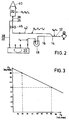
- Figure 3 shows the straight line for the flows F N and F R , the slope of the straight line resulting from the ratio of R0 / R GES , which according to the invention takes on a value of approximately 0.5.
- R0 or the ratio of R0 / R GES can be determined from the straight line equation above.
- the flow rate IR of the blood pump can be specified.
- the needle return flow F N can be determined directly using known pressure flow meters. If the pressure exerted by the printing press is constant, the slope of the straight line from Figure 3 can be determined directly, ie the ratio R0 / R GES can still be set within certain limits. So R0 can be increased by activating an adjustable clamp in the return line, which increases or decreases the flow resistance.
- a preselected hose system with a certain inner diameter and a certain length, ie a predetermined one Pressure flow resistance can be used.
- the flow resistance of the rest of the return system in particular the needle resistance
- the flow resistance of the return hose is either changed by means of an adjustable clamp or is already used in a preselected manner.
- a tube that can be used for blood cell separation and has an inside diameter of approximately 3 mm and the lengths and tube segments used there can be used advantageously.
- the reflux is not only determined by the pressure on the storage bag, but rather is also dependent on the hematocrit value and the viscosity of the blood, the latter parameters being largely regarded as constants during the treatment.
- the amount of tolerable anticoagulant flow through the reflux line depends on the size, weight and gender of the donor. For example, a small, light donor can tolerate significantly less anticoagulant per unit of time than a large, heavy donor.
- a reference table can be used for these relationships, wherein the hematocrit and the viscosity can also be taken into account.
- such a table is advantageously stored in the control device of the device according to the invention. Such a setting can be carried out by a microprocessor of the cell separator itself, by entering this table and the donor-specific values.
- the microprocessor selects a recirculation flow in which the backflow into the donor does not exceed a safety limit. According to the invention, this is essentially achieved with the flow rates given at the beginning.
- the recirculation carried out according to the invention in the single-needle method leads to a further and thus improved separation of the blood components to be separated, in particular the platelets. If, for example, about 50% of the platelets of the processed blood are collected in the collection bag in a 5-minute collection phase, a further 50% of the remaining platelets can be skimmed off in the return phase after 5 minutes of recirculation, so that a total of 75% of all separable platelets have now been separated .
- the return flow can be set at a constant recirculation rate by changing the flow resistance of the return line, for example by using a commercially available roller clamp.
- the choice of the cannula can also determine the maximum return flow. With the same recirculation flow, less will flow back to the donor with a thin one than with a thicker one. The determined values can be read in a diagram for different cannulas and return flows.
- the device according to the invention is shown at 10 in FIG.
- This device 10 has a cannula 12 for connection to a patient, the other end of which is connected to a Y-piece 14. From the Y-piece there is a feed line 16 into which a blood pump 18 is switched on. The end of the feed line 16 is connected to a centrifuge or separation device 20, in which a separation chamber, not shown, is arranged.
- a plasma line 22 extends from the centrifuge, into which a plasma pump 24 is switched on.
- the end of the plasma line 22 is connected to a storage bag 30 via a branching piece 26 and a connecting line 28.
- a platelet line 32 extends from the centrifuge 20, into which a platelet pump 34 is switched on and at the end of which a platelet receiving bag 36 is arranged.
- an erythrocyte line 38 branches off from the centrifuge 20 and is also connected to the storage bag 30 via the branching piece 26 and the connecting line 28.
- the storage bag 30 itself is arranged within a printing press 40 which exerts a predetermined pressure on the bag, this pressure being essentially independent of the degree of emptying of the storage bag 30.
- a return line 42 From the branching piece 26 there is a return line 42, the end of which is connected to the Y-piece 14.
- a drip chamber 44 and a clamp 46 and a throttle 48 are switched on, with which the cross section of the return line 42 can be changed.
- a flow measuring arrangement 50 is advantageously provided, which emits its signal via line 52 to a recirculation control device 54.
- This recirculation control device 54 is connected to an input 46 and itself controls the blood pump 18 in the recirculation phase and, if appropriate, the throttle 48 via the lines 58 and 60.
- the device according to FIG. 1 is operated as follows.
- a hose system is selected in which R0 is approximately half the total resistance consisting of R N , R0 and R P. If necessary, the throttle 48 is adjusted (either the hose diameter is expanded or narrowed) by measurement with the flow measuring device and adjustment of the throttle 48 after evaluation by the recirculation control device 54.
- patient-specific data and the desired needle and recirculation flows can be entered.
- the computer located in the control unit 54 can then set the recirculation speed of the blood pump 18 using the above-mentioned algorithm and, if necessary, change the throttle 48 to change the resistance of the return line 42.
- the operation of the single-needle device 10 itself is carried out as described, for example, in the aforementioned German Offenlegungsschrift, to which reference is made.
- the blood pump 18 is first activated in the collection phase, the clamp 46 remaining closed.
- the pump 14 for supplying anticoagulant is started up.
- the individual blood components separated in the centrifuge 20 are discharged with the aid of the plasma pump 24 or the platelet pump 34, the blood pump 18 additionally conveying the erythrocytes into the storage bag 30, in which they are mixed again with the plasma.
- the return phase takes place with the recirculation step.
- the clamp 46 is opened and the blood pump 18 is operated at the delivery rate for the recirculation. Since the blood is already provided with anticoagulant, the anticoagulant pump 66 is stopped, which pumps the anticoagulant to the supply line 16 via line 64 from an anticoagulant bag 62. On the other hand, the plasma pump 24 and the platelet pump 34 continue to operate.
- the system switches again to the separation cycle in which the patient's blood is fed to the centrifuge 20.
- the recirculation of less coagulant per unit of time can thus be returned to the patient and, moreover, the effectiveness of the separation can be increased.
Abstract
Description
- Die Erfindung betrifft eine Vorrichtung zur Trennung von Blut mit einer Kanüle gemäß dem Oberbegriff dfes Anspruchs 1.
- Eine Vorrichtung der eingangs erwähnten Art ist beispielsweise aus der DE-OS 39 31 471 oder dem Journal of Clinical Apheresis, Band 6, Seiten 24-27 (1991) bekannt.
- Das Einnadelverfahren bietet gegenüber den kontinuierlichen Zweinadelverfahren den Vorteil, daß der Spender nur ein einziges Mal mit einer Kanüle punktiert werden muß. Dies ist insbesondere von Vorteil, wenn schlechte Punktierungsverhältnisse vorliegen.
- Andererseits sind bei dem Einnadelverfahren zwei Zyklen durchzuführen, nämlich ein Kollektionszyklus, bei dem das von einer Vene abgezogene Blut zur Separation einer Zentrifuge zugeführt wird, in der die zu sammelnden und zurückzuführenden Blutfraktionen getrennt werden, und ein Rückgabezyklus, bei dem die zurückzuführenden Fraktionen zum Spender zurückgefördert werden, beispielsweise mittels einer zweiten Pumpe, wie dies in der DE-OS beschrieben ist oder mittels einer auf einen Speicherbeutel Druck ausübenden Einrichtung.
- Bei dem Einnadelverfahren treten zwei Probleme auf, nämlich eine vom Patienten abhängende Toleranz bezüglich des dem Blut zugemischten Antikoagulans und die teilweise eingeschränkte Effektivität der Separation.
- Was zunächst die Toleranz gegen das Antikoagulans betrifft, das zumeist in Form von ACD-A zugegeben wird, so wird letzteres von den Spendern bei der Rückgabe in die Armvene unterschiedlich gut vertragen. Bei hohen Rückgabeflüssen des Bluts gelangen ebenso hohe Anteile Antikoagulans zum Spender zurück. Andererseits verlängert sich bei kleinen Rückgabeflüssen die Rückgabezeit in entsprechender Weise. Wünschenswert ist daher eine Möglichkeit zur Einstellung des Rückgabeflusses.
- Was nun die teilweise beschränkte Effektivität der Separation betrifft, so läßt sich diese - wie dies bereits in der deutschen Offenlegungsschrift genannt ist - durch eine Rezirkulation des zurückgegebenen Bluts verbessern. In der Offenlegungsschrift ist jedoch nicht unmittelbar angegeben, mit welchen Steuerungsmitteln bei der dort beschriebenen Blutpumpe als Zuführungspumpe und einer in die Rückgabeleitung eingeschalteten zweiten Pumpe das geschehen soll.
- Der Erfindung liegt daher die Aufgabe zugrunde, die Vorrichtung der eingangs erwähnten Art derart zu verbessern, daß einerseits eine vorbestimmte Blutmenge dem Patienten zur Verbesserung der Toleranz zurückgeführt werden kann und andererseits die Effektivität der Separation gesteigert werden kann.
- Diese Aufgabe wird durch die kennzeichnenden Merkmale des Anspruchs 1 gelöst.
- Was zunächst die erfindungsgemäße Vorrichtung betrifft, so weist diese nur eine einzige Pumpe in Form einer Blutpumpe im Zuführungszweig auf, während im Abführungszweig lediglich eine auf den Speicherbeutel Druck ausübende Druckeinrichtung vorgesehen ist, gegen deren Druck der Speicherbeutel in der Kollektionsphase gefüllt wird und die auf den Speicherbeutel in der Rückgabephase vorteilhafterweise einen gleichbleibenden Druck ausübt. Eine derartige Druckeinrichtung ist in der mit dem Titel "Vorrichtung zum Entleeren von flexiblen Flüssigkeitsbehältern" eingereichten Patentanmeldung (unser Zeichen FR 2077) beschrieben, auf deren Offenbarung Bezug genommen wird.
- Demzufolge wird also in der Rückgabephase nicht eine mit einer vorbestimmten Förderphase arbeitende aktive Rückführpumpe, sondern vielmehr eine passive Druckeinrichtung eingesetzt, so daß der in dem gesamten Rückführsystem vorliegende Gesamtflußwiderstand ausschlaggebend ist für die dem Patienten zurückgeführte Blutmenge.
- Dieses Rückführsystem besteht üblicherweise aus drei Komponenten, nämlich dem Beutel einschließlich einer Verbindungsleitung zur Rückführleitung, der Rückführleitung selbst bis zum Y-Stück und der vom Y-Stück abgehenden Leitung einschließlich der Nadel selbst.
- Im einzelnen besteht der Gesamtflußwiderstand also aus den Teilflußwiderständen RP für den Innenwiderstand des Beutels einschließlich Zuführleitung, R₀ für den Zuführschlauchwiderstand und RN für den Nadelwiderstand. Sämtliche Teilflußwiderstände summieren sich zum Gesamtflußwiderstand RGES.
- Erfindungsgemäß beträgt der Flußwiderstand des Rückführschlauchs das 0,2-0,8fache, insbesondere etwa die Hälfte des Gesamtwiderstands RGES, wobei 'etwa' eine Abweichung von ± 20 % bedeutet. Mit einem solchen Verhältnis läßt sich ein Nadelrückfluß FN in medizinisch sinnvollen Grenzen von 50 - 80 ml/min einstellen, wobei zugleich eine Rezirkulationsrate FR im technisch für die Zentrifuge sinnvollen Bereich von 20 - 80 ml/min einstellbar ist. Zusätzlich ist in einem solchen Fall ein Druck P₀ mittels der Beutelpresse in einem Bereich von etwa 100 mmHg vorzugeben.
- Diese Parameter ergeben folgende Geradengleichung:

- In Abbildung 3 ist die Gerade für die Flüsse FN und FR dargestellt, wobei die Steigung der Geraden sich aus dem Verhältnis von R₀ / RGES ergibt, das erfindungsgemäß einen Wert von etwa 0,5 einnimmt.
- Aus der vorstehenden Geradengleichung läßt sich ohne weiteres R₀ bzw. das Verhältnis von R₀ / RGES bestimmten. Zum einen ist die Flußrate IR der Blutpumpe vorgebbar. Zum anderen kann mit Hilfe von bekannten Druckflußmessern der Nadelrückfluß FN unmittelbar bestimmt werden. Ist der von der Druckpresse ausgeübte Druck konstant, so kann direkt die Steigung der Geraden aus Abbildung 3 ermittelt werden, d.h. das Verhältnis R₀ / RGES kann in bestimmten Grenzen noch eingestellt werden. So kann R₀ dadurch erhöht werden, daß in die Rückführleitung eine einstellbare Klemme aktiviert wird, die den Flußwiderstand erhöht oder erniedrigt. Desgleichen kann natürlich auch ein vorgewähltes Schlauchsystem mit einem bestimmten Innendurchmesser und einer bestimmten Länge, d.h. einem vorbestimmten Druckflußwiderstand, eingesetzt werden. Schließlich kann natürlich auch der Durchflußwiderstand des Rests des Rückgabesystems, insbesondere der Nadelwiderstand, durch Wahl unterschiedlicher Nadelgrößen eingestellt werden. Üblicherweise wird jedoch der Durchflußwiderstand des Rückführschlauchs entweder mittels einer einstellbaren Klemme verändert oder aber bereits vorgewählt eingesetzt. So läßt sich beispielsweise ein für die Blutzellseparation einsetzbarer Schlauch mit einem Innendurchmesser von etwa 3 mm und den dort eingesetzten Längen und Schlauchsegmenten vorteilhaft einsetzen.
- Betrachtet man nunmehr die in Abbildung 3 angegebenen Verhältnisse, so ist ersichtlich, daß ohne Rezirkulation (FR = 0) ein Reinfusionsfluß von 90 ml/min erreicht werden kann, was nur durch die Einstellung des Gesamtwiderstands zu erreichen ist.
- Andererseits können durch Aktivierung der Blutpumpe als Rezirkulationspumpe unterschiedliche Reinfusionsflüsse, wie dies eingangs gefordert worden ist, erzielt werden, beispielsweise bei einem Rezirkulationsfluß von 80 ml/min ein Reinfusionsfluß von 50 ml/min. Dieser Reinfusionsfluß dauert natürlich nur so lange, bis der Speicherbeutel geleert ist, woraufhin ein neuer Kollektionszyklus eingeleitet wird.
- Es sei im übrigen noch darauf verwiesen, daß der Rückfluß nicht nur durch den Druck auf den Speicherbeutel bestimmt ist, sondern vielmehr auch abhängig ist vom Hämatokritwert und von der Viskosität des Bluts, wobei letztere Parameter während der Behandlung weitgehend als Konstanten zu betrachten sind.
- Die Menge des tolerierbaren Antikoagulans-Flusses durch die Rückflußleitung hängt von der Größe, dem Gewicht und dem Geschlecht des Spenders ab. So verträgt eine kleine leichte Spenderin wesentlich weniger Antikoagulans pro Zeiteinheit als ein großer schwerer Spender. Für diese Zusammenhänge kann erfindungsgemäß eine Referenztabelle benutzt werden, wobei zusätzlich der Hämatokrit und die Viskosität berücksichtigt werden können. Eine solche Tabelle wird erfindungsgemäß in der Steuervorrichtung der erfindungsgemäßen Vorrichtung vorteilhafterweise abgelegt. Eine solche Einstellung kann durch einen Mikroprozessor des Zellseparators selbst durchgeführt werden, indem diese Tabelle und die spenderspezifischen Werte eingegeben werden können. Der Mikroprozessor wählt also in Abhängigkeit vom Hämatokrit, Größe, Gewicht, Geschlecht des Spenders einen Rezirkulationsfluß aus, bei dem der Rückfluß in den Spender eine Sicherheitsgrenze nicht überschreitet. Erfindungsgemäß wird dies im wesentlichen mit den eingangs gegebenen Flußraten erreicht.
- Die erfindungsgemäß durchgeführte Rezirkulation bei dem Single-Needle-Verfahren führt zu einer weiteren und somit verbesserten Separation der abzutrennenden Blutbestandteile, insbesondere der Thrombozyten. Werden beispielsweise in einer 5-minütigen Kollektionsphase etwa 50 % der Thrombozyten des prozessierten Bluts im Kollektionsbeutel gesammelt, können in der Rückgabephase bei 5-minütiger Rezirkulation weitere 50 % der verbliebenen Thrombozyten abgeschöpft werden, so daß insgesamt 75 % aller abtrennbaren Thrombozyten nunmehr separiert worden sind.
- Die Erhöhung der Effektivität ist um so höher, je höher der Rezirkulationsfluß und je länger die Reinfusion dauert, wobei diese Zeitspannen gegeneinanderlaufen.
- Wie bereits vorstehend erwähnt, ist der Rückfluß bei konstanter Rezirkulationsrate durch die Veränderung des Flußwiderstandes der Rückführleitung einstellbar, beispielsweise durch Verwendung einer handelsüblichen Rollenklemme.
- In Abhängigkeit von der Verträglichkeit des Antikoagulans für den Spender läßt sich durch die Wahl der Kanüle weiterhin der maximale Rückgabefluß bestimmen. Bei gleichem Rezirkulationsfluß wird bei einer dünnen weniger zum Spender zurückfließen als bei einer dickeren. Die ermittelten Werte lassen sich für verschiedene Kanülen und Rückgabeflüsse dabei in einem Diagramm ablesen.
- Weitere Vorteile der Erfindung sind in dem nachstehend erläuterten Ausführungsbeispiel dargestellt.
- Es zeigen
- Figur 1
- eine schematische Anordnung einer erfindungsgemäßen Single-Needle-Anordnung,
- Figur 2
- eine weiter schematisierte Anordnung der Vorrichtung gemäß Figur 1 und
- Figur 3
- eine grafische Darstellung, in der die Abhängigkeit des Nadelrückflusses vom Rezirkulationsfluß bei dem Einsatz der erfindungsgemäßen Vorrichtung gezeigt ist.
- In Figur 1 ist mit 10 die erfindungsgemäße Vorrichtung gezeigt. Diese Vorrichtung 10 weist eine Kanüle 12 zum Anschluß an einen Patienten auf, deren anderes Ende mit einem Y-Stück 14 verbunden ist. Vom Y-Stück geht eine Zuführungsleitung 16 ab, in die eine Blutpumpe 18 eingeschaltet ist. Das Ende der Zuführungsleitung 16 ist mit einer Zentrifuge oder Separationseinrichtung 20 verbunden, in der eine nicht gezeigte Separationskammer angeordnet ist.
- Von der Zentrifuge geht eine Plasmaleitung 22 ab, in die eine Plasmapumpe 24 eingeschaltet ist. Das Ende der Plasmaleitung 22 ist über ein Verzweigungsstück 26 und eine Verbindungsleitung 28 mit einem Speicherbeutel 30 verbunden.
- Des weiteren geht von der Zentrifuge 20 eine Thrombozytenleitung 32 ab, in die eine Thrombozytenpumpe 34 eingeschaltet ist und an deren Ende ein Thrombozytenaufnahmebeutel 36 angeordnet ist.
- Schließlich geht von der Zentrifuge 20 eine Erythrozytenleitung 38 ab, die ebenfalls über das Verzeigungsstück 26 und die Verbindungsleitung 28 mit dem Speicherbeutel 30 verbunden ist.
- Der Speicherbeutel 30 selbst ist innerhalb einer Druckpresse 40 angeordnet, die auf den Beutel einen vorbestimmten Druck ausübt, wobei dieser Druck im wesentlichen vom Entleerungsgrad des Speicherbeutels 30 unabhängig ist.
- Vom Verzweigungsstück 26 geht eine Rückführungsleitung 42 ab, deren Ende mit dem Y-Stück 14 verbunden ist. In diese Rückführleitung 42 ist im Beispielsfalle eine Tropfkammer 44 und eine Klemme 46 sowie eine Drossel 48 eingeschaltet, mit der der Querschnitt der Rückführleitung 42 veränderbar ist.
- Schließlich ist im Bereich der Kanüle 14 vorteilhafterweise eine Durchflußmeßanordnung 50 vorgesehen, die ihr Signal über die Leitung 52 an ein Rezirkulationssteuergerät 54 abgibt. Dieses Rezirkulationssteuergerät 54 ist mit einer Eingabe 46 verbunden und steuert selbst über die Leitungen 58 und 60 die Blutpumpe 18 in der Rezirkulationsphase und gegebenenfalls die Drossel 48.
- Aus Übersichtlichkeitsgründen ist ein weiteres Steuergerät, mit dem die Single-Needle-Anordnung zwischen den beiden Separations- und Rückgabezyklen umgeschaltet wird, nicht gezeigt.
- In Figur 2 sind die Bezugszeichen gemäß Figur 1 für die gleichen Elemente verwandt worden. Zusätzlich wurden hier die Parameter für die einzelnen Elemente eingesetzt.
- Dabei bedeuten
- RN
- = Nadelwiderstand,
- R₀
- = Rückflußleitungswiderstand,
- RP
- = Innenwiderstand Beutelpresse und Verbindungsleitung,
- FR
- = Rezirkulationsfluß,
- FN
- = Nadelfluß,
- P₀
- = Druck-Beutelpresse.
- Die Parameter hängen über die eingangs genannte Gleichung voneineinander ab.
- Die Vorrichtung gemäß Figur 1 wird folgendermaßen betrieben.
- Es wird ein Schlauchsystem ausgewählt, bei dem R₀ etwa die Hälfte des Gesamtwiderstandes bestehend aus RN, R₀ und RP, ist. Gegebenfalls wird durch Messung mit dem Durchflußmeßgerät und Verstellung der Drossel 48 nach Auswertung durch die Rezirkulationssteuereinrichtung 54 die Drossel 48 verstellt (entweder der Schlauchdurchmesser erweitert oder verengt).
- Über die Eingabe 56 können patientenspezifische Daten sowie die angestrebten Nadel- und Rezirkulationsflüsse eingegeben werden. Der im Steuergerät 54 befindliche Rechner kann dann über den vorstehend genannten Algorithmus die Rezirkulationsgeschwindigkeit der Blutpumpe 18 einstellen und gegebenenfalls die Drossel 48 zur Veränderung des Widerstands der Rückführleitung 42 verändern.
- Der Betrieb der Single-Needle-Vorrichtung 10 selbst erfolgt wie er beispielsweise in der eingangs genannten deutschen Offenlegungsschrift beschrieben ist, worauf Bezug genommen. Insofern wird in der Kollektionsphase zunächst die Blutpumpe 18 aktiviert, wobei die Klemme 46 geschlossen bleibt. Zugleich wird die Pumpe 14 zur Zuführung von Antikoagulans in Betrieb genommen. Die einzelnen in der Zentrifuge 20 getrennten Blutbestandteile werden mit Hilfe der Plasmapumpe 24 bzw. der Thrombozytenpumpe 34 abgeführt, wobei zusätzlich die Blutpumpe 18 die Erythrozyten in den Speicherbeutel 30 befördert, in dem sie mit dem Plasma wieder vermischt werden.
- Nach Beendigung der Kollektionsphase erfolgt die Rückführphase mit dem Rezirkulationsschritt. Hierzu wird die Klemme 46 geöffnet und die Blutpumpe 18 wird mit der Förderrate für die Rezirkulation betrieben. Da das Blut bereits mit Antikoagulans versehen ist, wird die Antikoagulanspumpe 66 angehalten, die über die Leitung 64 von einem Antikoagulansbeutel 62 das Antikoagulans der Zuführleitung 16 zufördert. Andererseits werden die Plasmapumpe 24 und die Thrombozytenpumpe 34 weiterbetrieben.
- Nach Beendigung des Rückführzyklus und der Rezirkulation wird erneut in den Separationszyklus umgeschaltet, in dem das Blut des Patienten der Zentrifuge 20 zugeführt wird.
- Mit Hilfe der erfindungsgemäßen Vorrichtung 10 kann also durch die Rezirkulation weniger Koagulans je Zeiteinheit dem Patienten zurückgeführt und darüber hinaus die Effektivität der Separation erhöht werden.
Claims (5)
- Vorrichtung zur Trennung von Blut mit einer Kanüle zum Anschluß an einen Patienten, einem mit der Kanüle verbundenen Y-Stück, einer vom Y-Stück abgehenden Zuführungsleitung, in die eine Blutpumpe eingeschaltet ist, einer Zentrifuge, die mit der Zuführungsleitung verbunden ist und eine Separationskammer aufweist, einer Plasmaabzugsleitung, die von der Separationskammer abgeht und in den Speicherbeutel mündet und in die eine Plasmapumpe eingeschaltet ist, einer von der Separationskammer abgehenden und in einen Thrombozytensammelbeutel mündende Thrombozytenabzugsleitung, einer Rückführleitung, die vom Speicherbeutel abgeht und mit der Kanüle verbunden ist, einem Antikoagulans enthaltenden Antikoagulans-Beutel, der über eine Nebenleitung, in die eine Antikoagulans-Pumpe eingeschaltet ist, mit der Zuführungsleitung verbunden ist, einer auf den Speicherbeutel Druck ausübenden Einrichtung zum Rückführen des gespeicherten Blut-/Plasmagemisches aus dem Speicherbeutel sowie mit Steuermitteln zum wechselweisen Akivieren der Blutpumpe, Antikoagulans-Pumpe und Thrombozytenpumpe einerseits und die Rückführeinrichtung andererseits von einer Kollektionsphase in eine Rückgabephase und zurück schaltet, dadurch gekennzeichnet, daß der Flußwiderstand R₀ der Rückführleitung (42) das 0,2-0,8fache, insbesondere etwa die Hälfte des Flußwiderstands des restlichen Rückführsystems (28, 30, 14, 12) beträgt, die Druckeinrichtung (40) auf einen vorbestimmten Druck vorgespannt ist und die Blutpumpe (18) in der Rückführphase mit einer vorbestimmten Förderrate einen Teil des rückgeführten Blut-/Plasmagemisches durch die Zuführungsleitung erneut der Zentrifuge zuführt.
- Vorrichtung nach Anspruch 1, dadurch gekennzeichnet, daß bei einem vorgegebenen Druck P₀ der Druckeinrichtung (40) von etwa 100 mmHg der Nadelfluß FN 50 bzw. 80 ml/min bei einem vorbestimmten Rezirkulationsfluß FR von 80 bzw. 20 ml/min beträgt, wobei die Rezirkulationsförderraten FR mit den Nadelflußraten FN entsprechend der Gleichung

korreliert sind. - Vorrichtung nach Anspruch 1 oder 2, dadurch gekennzeichnet, daß in der Rückführleitung (42) eine verstellbare Drossel (48) angeordnet ist, mit der der Flußwiderstand R₀ der Rückführleitung (42) einstellbar ist.
- Vorrichtung nach Anspruch 3, dadurch gekennzeichnet, daß im Bereich der Kanüle (12) ein Durchflußmesser (50) angeordnet ist, dessen Signal von einem Rezirkulationssteuergerät (54) entsprechend dem Algorithmus gemäß Anspruch 2 zur Aktivierung der Drossel (48) und/oder der Rezirkulationspumpe (18) eingesetzt wird.
- Vorrichtung nach Anspruch 4, dadurch gekennzeichnet, daß das Rezirkulationssteuergerät (54) mit einer Eingabeeinheit (56) verbunden ist, mit der patientenspezifische Daten sowie Flußraten von Nadel (12) und der Blutpumpe (18) eingebbar sind.
Applications Claiming Priority (2)
| Application Number | Priority Date | Filing Date | Title |
|---|---|---|---|
| DE4129639 | 1991-09-06 | ||
| DE4129639A DE4129639C1 (de) | 1991-09-06 | 1991-09-06 |
Publications (2)
| Publication Number | Publication Date |
|---|---|
| EP0530689A1 true EP0530689A1 (de) | 1993-03-10 |
| EP0530689B1 EP0530689B1 (de) | 1999-01-13 |
Family
ID=6439998
Family Applications (1)
| Application Number | Title | Priority Date | Filing Date |
|---|---|---|---|
| EP92114688A Expired - Lifetime EP0530689B1 (de) | 1991-09-06 | 1992-08-28 | Vorrichtung zur Rezirkulation im Single-Needle-Verfahren bei der Zellseparation |
Country Status (5)
| Country | Link |
|---|---|
| US (1) | US5318512A (de) |
| EP (1) | EP0530689B1 (de) |
| JP (1) | JP2521874B2 (de) |
| DE (2) | DE4129639C1 (de) |
| ES (1) | ES2129420T3 (de) |
Cited By (1)
| Publication number | Priority date | Publication date | Assignee | Title |
|---|---|---|---|---|
| EP0588071A2 (de) * | 1992-08-21 | 1994-03-23 | Fresenius AG | Zentrifuge zum Trennen von Blut in seine Bestandteile |
Families Citing this family (35)
| Publication number | Priority date | Publication date | Assignee | Title |
|---|---|---|---|---|
| US5833866A (en) * | 1991-12-23 | 1998-11-10 | Baxter International Inc. | Blood collection systems and methods which derive instantaneous blood component yield information during blood processing |
| US6007725A (en) | 1991-12-23 | 1999-12-28 | Baxter International Inc. | Systems and methods for on line collection of cellular blood components that assure donor comfort |
| US5730883A (en) | 1991-12-23 | 1998-03-24 | Baxter International Inc. | Blood processing systems and methods using apparent hematocrit as a process control parameter |
| US5690835A (en) | 1991-12-23 | 1997-11-25 | Baxter International Inc. | Systems and methods for on line collection of cellular blood components that assure donor comfort |
| US5639382A (en) * | 1991-12-23 | 1997-06-17 | Baxter International Inc. | Systems and methods for deriving recommended storage parameters for collected blood components |
| US5676841A (en) * | 1991-12-23 | 1997-10-14 | Baxter International Inc. | Blood processing systems and methods which monitor citrate return to the donor |
| US5681273A (en) * | 1991-12-23 | 1997-10-28 | Baxter International Inc. | Systems and methods for predicting blood processing parameters |
| US5733253A (en) * | 1994-10-13 | 1998-03-31 | Transfusion Technologies Corporation | Fluid separation system |
| US7332125B2 (en) * | 1994-10-13 | 2008-02-19 | Haemonetics Corporation | System and method for processing blood |
| US6632191B1 (en) | 1994-10-13 | 2003-10-14 | Haemonetics Corporation | System and method for separating blood components |
| US5651766A (en) | 1995-06-07 | 1997-07-29 | Transfusion Technologies Corporation | Blood collection and separation system |
| US5759413A (en) | 1995-06-07 | 1998-06-02 | Baxter International Inc. | Systems and method for estimating platelet counts using a spleen mobilization function |
| US6251284B1 (en) | 1995-08-09 | 2001-06-26 | Baxter International Inc. | Systems and methods which obtain a uniform targeted volume of concentrated red blood cells in diverse donor populations |
| US5762791A (en) * | 1995-08-09 | 1998-06-09 | Baxter International Inc. | Systems for separating high hematocrit red blood cell concentrations |
| US6527957B1 (en) | 1995-08-09 | 2003-03-04 | Baxter International Inc. | Methods for separating, collecting and storing red blood cells |
| EP0834329A1 (de) * | 1996-09-09 | 1998-04-08 | Kaneka Corporation | Verfahren und Vorrichtung zur Behandlung von Blut |
| US6852074B1 (en) * | 1997-05-20 | 2005-02-08 | Zymequest, Inc. | Biological processing apparatus for expressing fluid material |
| EP1011752B1 (de) * | 1997-05-20 | 2004-10-13 | Zymequest, Inc. | Gerät und verfahren zur verarbeitung von biologischen zellen |
| US6175420B1 (en) | 1998-05-20 | 2001-01-16 | Zymequest, Inc. | Optical sensors for cell processing systems |
| JP5015379B2 (ja) * | 1999-03-17 | 2012-08-29 | ヘモネティクス・コーポレーション | 血液を処理するための装置及び方法 |
| US6296602B1 (en) | 1999-03-17 | 2001-10-02 | Transfusion Technologies Corporation | Method for collecting platelets and other blood components from whole blood |
| US6890291B2 (en) * | 2001-06-25 | 2005-05-10 | Mission Medical, Inc. | Integrated automatic blood collection and processing unit |
| US7037428B1 (en) | 2002-04-19 | 2006-05-02 | Mission Medical, Inc. | Integrated automatic blood processing unit |
| US7087177B2 (en) * | 2004-04-16 | 2006-08-08 | Baxter International Inc. | Methods for determining flow rates of biological fluids |
| US8702637B2 (en) * | 2008-04-14 | 2014-04-22 | Haemonetics Corporation | System and method for optimized apheresis draw and return |
| US8454548B2 (en) * | 2008-04-14 | 2013-06-04 | Haemonetics Corporation | System and method for plasma reduced platelet collection |
| US8628489B2 (en) | 2008-04-14 | 2014-01-14 | Haemonetics Corporation | Three-line apheresis system and method |
| US8834402B2 (en) | 2009-03-12 | 2014-09-16 | Haemonetics Corporation | System and method for the re-anticoagulation of platelet rich plasma |
| CN103221078B (zh) | 2010-11-05 | 2015-09-16 | 赫摩耐提克斯公司 | 用于自动化血小板洗涤的系统和方法 |
| US9302042B2 (en) | 2010-12-30 | 2016-04-05 | Haemonetics Corporation | System and method for collecting platelets and anticipating plasma return |
| US11386993B2 (en) | 2011-05-18 | 2022-07-12 | Fenwal, Inc. | Plasma collection with remote programming |
| WO2019226654A1 (en) | 2018-05-21 | 2019-11-28 | Fenwal, Inc. | Systems and methods for optimization of plasma collection volumes |
| US10758652B2 (en) | 2017-05-30 | 2020-09-01 | Haemonetics Corporation | System and method for collecting plasma |
| US10792416B2 (en) | 2017-05-30 | 2020-10-06 | Haemonetics Corporation | System and method for collecting plasma |
| US11412967B2 (en) | 2018-05-21 | 2022-08-16 | Fenwal, Inc. | Systems and methods for plasma collection |
Citations (5)
| Publication number | Priority date | Publication date | Assignee | Title |
|---|---|---|---|---|
| EP0132210A1 (de) * | 1983-07-13 | 1985-01-23 | Rhone-Poulenc S.A. | Gerät für Plasmapherese |
| WO1988002641A1 (en) * | 1986-10-15 | 1988-04-21 | Baxter Travenol Laboratories, Inc. | Mobile, self-contained blood collection system and method |
| EP0392304A1 (de) * | 1989-04-08 | 1990-10-17 | Dialyse-Technik med. Geräte Handels GmbH | Vorrichtung und Verfahren zur Dialyse |
| EP0155684B1 (de) * | 1984-03-21 | 1990-10-24 | Fresenius AG | Vorrichtung zur Trennung von Blut |
| DE3931471A1 (de) * | 1989-09-21 | 1991-04-11 | Fresenius Ag | Verfahren und vorrichtung zur trennung von blut mittels einer zentrifuge |
Family Cites Families (13)
| Publication number | Priority date | Publication date | Assignee | Title |
|---|---|---|---|---|
| US3489145A (en) * | 1966-08-08 | 1970-01-13 | Surgeon General Of The Public | Method and apparatus for continuous separation of blood in vivo |
| US4185629A (en) * | 1977-10-18 | 1980-01-29 | Baxter Travenol Laboratories, Inc. | Method and apparatus for processing blood |
| US4460353A (en) * | 1980-09-08 | 1984-07-17 | Imed Corporation | Drop controller |
| US4605503A (en) * | 1983-05-26 | 1986-08-12 | Baxter Travenol Laboratories, Inc. | Single needle blood fractionation system having adjustable recirculation through filter |
| US4553963A (en) * | 1984-05-16 | 1985-11-19 | American Hospital Supply Corp. | Roller clamp controller |
| SE8601891D0 (sv) * | 1986-04-24 | 1986-04-24 | Svante Jonsson | Maskin for plasmabytesbehandling och trombocytgivning |
| DE3632176A1 (de) * | 1986-09-22 | 1988-04-07 | Fresenius Ag | Steuerung eines systems zur trennung der bestandteile des einem spender "in vivo" entnommenen blutes |
| US4911703A (en) * | 1986-10-15 | 1990-03-27 | Baxter International Inc. | Mobile, self-contained blood collection system and method |
| US4827970A (en) * | 1986-12-18 | 1989-05-09 | Kawasumi Laboratories, Inc. | Device for controlling liquid dropping |
| GB8724914D0 (en) * | 1987-10-23 | 1987-11-25 | Research Corp Ltd | Blood purification apparatus |
| US5186431A (en) * | 1989-09-22 | 1993-02-16 | Yehuda Tamari | Pressure sensitive valves for extracorporeal circuits |
| US5112298A (en) * | 1990-06-25 | 1992-05-12 | Baxter International Inc. | Apheresis method and device |
| DE4129271C1 (de) * | 1991-09-03 | 1992-09-17 | Fresenius Ag, 6380 Bad Homburg, De |
-
1991
- 1991-09-06 DE DE4129639A patent/DE4129639C1/de not_active Expired - Fee Related
-
1992
- 1992-08-28 JP JP4253872A patent/JP2521874B2/ja not_active Expired - Lifetime
- 1992-08-28 DE DE59209615T patent/DE59209615D1/de not_active Expired - Lifetime
- 1992-08-28 ES ES92114688T patent/ES2129420T3/es not_active Expired - Lifetime
- 1992-08-28 EP EP92114688A patent/EP0530689B1/de not_active Expired - Lifetime
- 1992-09-03 US US07/939,672 patent/US5318512A/en not_active Expired - Fee Related
Patent Citations (5)
| Publication number | Priority date | Publication date | Assignee | Title |
|---|---|---|---|---|
| EP0132210A1 (de) * | 1983-07-13 | 1985-01-23 | Rhone-Poulenc S.A. | Gerät für Plasmapherese |
| EP0155684B1 (de) * | 1984-03-21 | 1990-10-24 | Fresenius AG | Vorrichtung zur Trennung von Blut |
| WO1988002641A1 (en) * | 1986-10-15 | 1988-04-21 | Baxter Travenol Laboratories, Inc. | Mobile, self-contained blood collection system and method |
| EP0392304A1 (de) * | 1989-04-08 | 1990-10-17 | Dialyse-Technik med. Geräte Handels GmbH | Vorrichtung und Verfahren zur Dialyse |
| DE3931471A1 (de) * | 1989-09-21 | 1991-04-11 | Fresenius Ag | Verfahren und vorrichtung zur trennung von blut mittels einer zentrifuge |
Cited By (3)
| Publication number | Priority date | Publication date | Assignee | Title |
|---|---|---|---|---|
| EP0588071A2 (de) * | 1992-08-21 | 1994-03-23 | Fresenius AG | Zentrifuge zum Trennen von Blut in seine Bestandteile |
| EP0588071A3 (de) * | 1992-08-21 | 1994-10-26 | Fresenius Ag | Zentrifuge zum Trennen von Blut in seine Bestandteile. |
| US5386734A (en) * | 1992-08-21 | 1995-02-07 | Fresenius Ag | Centrifuge system for the separation of blood into its components |
Also Published As
| Publication number | Publication date |
|---|---|
| ES2129420T3 (es) | 1999-06-16 |
| DE59209615D1 (de) | 1999-02-25 |
| EP0530689B1 (de) | 1999-01-13 |
| US5318512A (en) | 1994-06-07 |
| DE4129639C1 (de) | 1993-02-11 |
| JPH05200108A (ja) | 1993-08-10 |
| JP2521874B2 (ja) | 1996-08-07 |
Similar Documents
| Publication | Publication Date | Title |
|---|---|---|
| DE4129639C1 (de) | ||
| DE4227695C1 (de) | Zentrifuge zum Auftrennen von Blut in seine Bestandteile | |
| EP1539271B1 (de) | Blutbehandlungsvorrichtung mit blutrückgabe | |
| DE69629657T2 (de) | System und methode zur trennung von erythrocyten | |
| EP0373455B1 (de) | Vorrichtung zur kontinuierlichen Hämofiltration und Hämodiafiltration | |
| DE3837298C1 (de) | ||
| DE3524824C2 (de) | ||
| EP0155684B1 (de) | Vorrichtung zur Trennung von Blut | |
| EP0438703B1 (de) | System zur Sammlung und Retransfusion von autologem Blut | |
| EP2736554B1 (de) | Verfahren zum entfernen von fluid aus einem blutfilter nach beendigung einer blutbehandlungssitzung und behandlungsvorrichtung zum durchführen desselben | |
| DE2754894A1 (de) | Vorrichtung zur fluessigkeits-bilanzierung unter sterilen bedingungen | |
| EP0812596A1 (de) | Schwerkraft-Infusionsvorrichtung für medizinische Infusionen | |
| EP0148319A1 (de) | Dialysevorrichtung | |
| EP3515530B1 (de) | Steuerungs- und regelungseinrichtung sowie behandlungsvorrichtung zum durchführen eines verfahrens zum entfernen von blut aus einem extrakorporalen blutkreislauf nach beendigung einer blutbehandlungssitzung | |
| DE4240681A1 (de) | Vorrichtung zur Hämodialyse ohne Antikoagulation | |
| WO2016001217A1 (de) | Verfahren zum entfernen von fluid aus einem blutfilter nach beendigung einer blutbehandlungssitzung mittels flusserhöhung und behandlungsvorrichtung zum durchführen desselben | |
| EP3449960A2 (de) | Verfahren zum entfernen von blut aus einem extrakorporalen blutkreislauf sowie vorrichtungen | |
| EP0208061A1 (de) | Verfahren und Vorrichtung zur Gewinnung von Blutplasma | |
| EP3021886A2 (de) | Verfahren zum steuern einer blutbehandlungsvorrichtung und vorrichtungen | |
| WO2020011784A1 (de) | Steuerungs- und/oder regelungseinrichtung zum entfernen von fluid aus einem blutfilter | |
| EP0513672B1 (de) | Vorrichtung zur Behandlung von Blut mit volumetrischer Flüssigkeitsbilanzierung | |
| EP3197520B1 (de) | Vorrichtungen zum vorbereiten eines extrakorporalen blutkreislaufs für die blutbehandlung | |
| EP3817793B1 (de) | Verfahren zum automatisierten primen eines extrakorporalen blutleitungssystems sowie eine vorrichtung hierfür | |
| DE10245619A1 (de) | Verfahren zur Blutrückgabe aus einer Blutbehandlungsvorrichtung und Vorrichtung zur Durchführung des Verfahrens | |
| EP1393770A1 (de) | Medizinisches Arbeitsmittel |
Legal Events
| Date | Code | Title | Description |
|---|---|---|---|
| PUAI | Public reference made under article 153(3) epc to a published international application that has entered the european phase |
Free format text: ORIGINAL CODE: 0009012 |
|
| AK | Designated contracting states |
Kind code of ref document: A1 Designated state(s): DE ES FR GB IT |
|
| 17P | Request for examination filed |
Effective date: 19930714 |
|
| 17Q | First examination report despatched |
Effective date: 19950123 |
|
| GRAG | Despatch of communication of intention to grant |
Free format text: ORIGINAL CODE: EPIDOS AGRA |
|
| GRAG | Despatch of communication of intention to grant |
Free format text: ORIGINAL CODE: EPIDOS AGRA |
|
| GRAH | Despatch of communication of intention to grant a patent |
Free format text: ORIGINAL CODE: EPIDOS IGRA |
|
| GRAH | Despatch of communication of intention to grant a patent |
Free format text: ORIGINAL CODE: EPIDOS IGRA |
|
| GRAA | (expected) grant |
Free format text: ORIGINAL CODE: 0009210 |
|
| AK | Designated contracting states |
Kind code of ref document: B1 Designated state(s): DE ES FR GB IT |
|
| REF | Corresponds to: |
Ref document number: 59209615 Country of ref document: DE Date of ref document: 19990225 |
|
| ITF | It: translation for a ep patent filed |
Owner name: STUDIO TORTA S.R.L. |
|
| GBT | Gb: translation of ep patent filed (gb section 77(6)(a)/1977) |
Effective date: 19990308 |
|
| ET | Fr: translation filed | ||
| REG | Reference to a national code |
Ref country code: ES Ref legal event code: FG2A Ref document number: 2129420 Country of ref document: ES Kind code of ref document: T3 |
|
| PLBE | No opposition filed within time limit |
Free format text: ORIGINAL CODE: 0009261 |
|
| STAA | Information on the status of an ep patent application or granted ep patent |
Free format text: STATUS: NO OPPOSITION FILED WITHIN TIME LIMIT |
|
| 26N | No opposition filed | ||
| PGFP | Annual fee paid to national office [announced via postgrant information from national office to epo] |
Ref country code: FR Payment date: 20010717 Year of fee payment: 10 |
|
| PGFP | Annual fee paid to national office [announced via postgrant information from national office to epo] |
Ref country code: GB Payment date: 20010719 Year of fee payment: 10 |
|
| PGFP | Annual fee paid to national office [announced via postgrant information from national office to epo] |
Ref country code: ES Payment date: 20010730 Year of fee payment: 10 |
|
| REG | Reference to a national code |
Ref country code: GB Ref legal event code: IF02 |
|
| PG25 | Lapsed in a contracting state [announced via postgrant information from national office to epo] |
Ref country code: GB Free format text: LAPSE BECAUSE OF NON-PAYMENT OF DUE FEES Effective date: 20020828 |
|
| PG25 | Lapsed in a contracting state [announced via postgrant information from national office to epo] |
Ref country code: ES Free format text: LAPSE BECAUSE OF NON-PAYMENT OF DUE FEES Effective date: 20020829 |
|
| GBPC | Gb: european patent ceased through non-payment of renewal fee |
Effective date: 20020828 |
|
| PG25 | Lapsed in a contracting state [announced via postgrant information from national office to epo] |
Ref country code: FR Free format text: LAPSE BECAUSE OF NON-PAYMENT OF DUE FEES Effective date: 20030430 |
|
| REG | Reference to a national code |
Ref country code: FR Ref legal event code: ST |
|
| REG | Reference to a national code |
Ref country code: ES Ref legal event code: FD2A Effective date: 20030912 |
|
| PG25 | Lapsed in a contracting state [announced via postgrant information from national office to epo] |
Ref country code: IT Free format text: LAPSE BECAUSE OF NON-PAYMENT OF DUE FEES;WARNING: LAPSES OF ITALIAN PATENTS WITH EFFECTIVE DATE BEFORE 2007 MAY HAVE OCCURRED AT ANY TIME BEFORE 2007. THE CORRECT EFFECTIVE DATE MAY BE DIFFERENT FROM THE ONE RECORDED. Effective date: 20050828 |
|
| PGFP | Annual fee paid to national office [announced via postgrant information from national office to epo] |
Ref country code: DE Payment date: 20110831 Year of fee payment: 20 |
|
| REG | Reference to a national code |
Ref country code: DE Ref legal event code: R071 Ref document number: 59209615 Country of ref document: DE |
|
| REG | Reference to a national code |
Ref country code: DE Ref legal event code: R071 Ref document number: 59209615 Country of ref document: DE |
|
| PG25 | Lapsed in a contracting state [announced via postgrant information from national office to epo] |
Ref country code: DE Free format text: LAPSE BECAUSE OF EXPIRATION OF PROTECTION Effective date: 20120829 |