EP0530516B1 - Multiple speed automatic transaxle for automotive vehicles - Google Patents
Multiple speed automatic transaxle for automotive vehicles Download PDFInfo
- Publication number
- EP0530516B1 EP0530516B1 EP92113217A EP92113217A EP0530516B1 EP 0530516 B1 EP0530516 B1 EP 0530516B1 EP 92113217 A EP92113217 A EP 92113217A EP 92113217 A EP92113217 A EP 92113217A EP 0530516 B1 EP0530516 B1 EP 0530516B1
- Authority
- EP
- European Patent Office
- Prior art keywords
- gear
- clutch
- carrier
- gear unit
- brake
- Prior art date
- Legal status (The legal status is an assumption and is not a legal conclusion. Google has not performed a legal analysis and makes no representation as to the accuracy of the status listed.)
- Expired - Lifetime
Links
- 230000008878 coupling Effects 0.000 claims description 58
- 238000010168 coupling process Methods 0.000 claims description 58
- 238000005859 coupling reaction Methods 0.000 claims description 58
- 230000005540 biological transmission Effects 0.000 claims description 23
- 230000001970 hydrokinetic effect Effects 0.000 claims description 3
- 238000006243 chemical reaction Methods 0.000 description 6
- 230000001360 synchronised effect Effects 0.000 description 3
- 150000001875 compounds Chemical class 0.000 description 2
- 230000033001 locomotion Effects 0.000 description 2
- 230000001133 acceleration Effects 0.000 description 1
- 238000002485 combustion reaction Methods 0.000 description 1
- 238000010586 diagram Methods 0.000 description 1
- 230000009977 dual effect Effects 0.000 description 1
- 239000012530 fluid Substances 0.000 description 1
Images


Classifications
-
- F—MECHANICAL ENGINEERING; LIGHTING; HEATING; WEAPONS; BLASTING
- F16—ENGINEERING ELEMENTS AND UNITS; GENERAL MEASURES FOR PRODUCING AND MAINTAINING EFFECTIVE FUNCTIONING OF MACHINES OR INSTALLATIONS; THERMAL INSULATION IN GENERAL
- F16H—GEARING
- F16H3/00—Toothed gearings for conveying rotary motion with variable gear ratio or for reversing rotary motion
- F16H3/44—Toothed gearings for conveying rotary motion with variable gear ratio or for reversing rotary motion using gears having orbital motion
- F16H3/62—Gearings having three or more central gears
- F16H3/66—Gearings having three or more central gears composed of a number of gear trains without drive passing from one train to another
-
- F—MECHANICAL ENGINEERING; LIGHTING; HEATING; WEAPONS; BLASTING
- F16—ENGINEERING ELEMENTS AND UNITS; GENERAL MEASURES FOR PRODUCING AND MAINTAINING EFFECTIVE FUNCTIONING OF MACHINES OR INSTALLATIONS; THERMAL INSULATION IN GENERAL
- F16H—GEARING
- F16H47/00—Combinations of mechanical gearing with fluid clutches or fluid gearing
- F16H47/06—Combinations of mechanical gearing with fluid clutches or fluid gearing the fluid gearing being of the hydrokinetic type
- F16H47/08—Combinations of mechanical gearing with fluid clutches or fluid gearing the fluid gearing being of the hydrokinetic type the mechanical gearing being of the type with members having orbital motion
-
- F—MECHANICAL ENGINEERING; LIGHTING; HEATING; WEAPONS; BLASTING
- F16—ENGINEERING ELEMENTS AND UNITS; GENERAL MEASURES FOR PRODUCING AND MAINTAINING EFFECTIVE FUNCTIONING OF MACHINES OR INSTALLATIONS; THERMAL INSULATION IN GENERAL
- F16H—GEARING
- F16H2200/00—Transmissions for multiple ratios
- F16H2200/003—Transmissions for multiple ratios characterised by the number of forward speeds
- F16H2200/0047—Transmissions for multiple ratios characterised by the number of forward speeds the gear ratios comprising five forward speeds
-
- F—MECHANICAL ENGINEERING; LIGHTING; HEATING; WEAPONS; BLASTING
- F16—ENGINEERING ELEMENTS AND UNITS; GENERAL MEASURES FOR PRODUCING AND MAINTAINING EFFECTIVE FUNCTIONING OF MACHINES OR INSTALLATIONS; THERMAL INSULATION IN GENERAL
- F16H—GEARING
- F16H2200/00—Transmissions for multiple ratios
- F16H2200/20—Transmissions using gears with orbital motion
- F16H2200/2002—Transmissions using gears with orbital motion characterised by the number of sets of orbital gears
- F16H2200/2012—Transmissions using gears with orbital motion characterised by the number of sets of orbital gears with four sets of orbital gears
Definitions
- the present invention relates to a multiple speed automatic transaxle for an automotive vehicle of the kind as referred to in the preamble of claim 1 and known from EP-A-037 169.
- U.S. Patent 4,418,585 has clutches and brakes arranged so that a gear ratio change from the lowest speed to the second speed is made nonsynchronously, i.e., by transferring torque from an overrunning coupling to a friction clutch.
- a gear shift from the second speed to the third speed requires disengagement of the brake band and application of a clutch.
- a gear ratio change from the third speed to the fourth or overdrive speed also requires disengagement of a brake band and engagement of a friction clutch.
- none of the gear shifts require synchronous disengagement of a clutch and engagement of another clutch. Therefore, timing problems in the engagement and release of the clutch brake control servos are eliminated.
- the transmission according to the '585 patent requires time for disengagement of a high speed ratio clutch and application of a friction brake in order to produce the ratio change from the third forward speed to the fourth overdrive speed.
- U.S. Patent 4,368,649 describes a four-speed transaxle that overcomes this difficulty.
- the gear shift from the third speed to the fourth speed results by applying a single friction brake in addition to the other friction elements engaged during the third speed ratio.
- a gear shift from the first speed to the second forward speed results merely by engaging a second friction clutch while a companion friction clutch remains applied.
- a ratio change from the first ratio and from the third ratio in the forward driving speed range results merely by engaging or disengaging a single friction element, either a clutch or a brake, thereby greatly simplifying control of the clutches and eliminating potential for harsh or abrupt gear shift changes.
- U.S. Patent 4,509,389 describes a further improvement that eliminates a latent difficulty in control of the transmission of the '649 patent that makes calibration of the two-three upshift difficult.
- the sun gear is not connected to a friction clutch cylinder but is connected instead to the inner race of an associated one-way clutch.
- the inner races of each one-way coupling are connected to a common member, which operates as a torque delivery element for the input sun gear of the planetary gear.
- the maximum speed of the friction clutch cylinders is equal to the speed of the driven sprocket of a chain mechanism connecting the output of a torque converter to the input shaft of the transmission.
- U.S. Patent 4,086,827 describes a four speed transmission in which a single one-way clutch is located in series between an input friction clutch and a gear member of a planetary gear set.
- the one-way clutch permits the gear member to overrun the input during an overdrive ratio so that an upshift from the third speed to the fourth speed results without a synchronous release of the input friction clutch.
- the input increases to the speed of the gear member by engagement of the one-way clutch when a friction brake or another friction clutch is released.
- the present invention as claimed in claim 1 provides for five forward speeds and a reverse drive ratio, and is an improvement over the four speed transaxle described in EP-A-037 169.
- the present invention is a two-axis transaxle having preferably a hydrokinetic torque converter mounted on an axis concentric with the engine crankshaft and parallel to the axis of the multiple speed gearing.
- the transaxle produces two underspeed ratios, a direct drive ratio, two overspeed ratios and a reverse drive ratio.
- the transaxle is extremely compact and its weight is low.
- the compactness of the transaxle is the result of use of certain components of the transaxle for multiple purposes to produce multiple speed ratios.
- the structure that provides the gearset reaction force through a one-way coupling in intermediate speed ranges, the second and third speed ratios, is used also to transmit torque converter turbine torque in the reverse drive condition.
- the torque path between the engine and the planetary gear in the reverse drive condition is through a reverse friction clutch and a drum that provides a surface engaged by an intermediate brake band and the friction plate of the reverse friction clutch.
- a one-way coupling located between the gear units and engine, overruns in the reverse coast condition.
- the engine is driveably disconnected from the wheels and therefore unavailable to impede vehicle movement. This avoids abrupt unexpected changes in acceleration when the operator changes from drive to coast conditions in the reverse range.
- the transaxle includes three planetary gear units each including a sun gear, a ring gear, a carrier and planetary pinions rotatably supported on the carrier and meshing with the sun gear and ring gear.
- the carrier of the first gear unit is fixed to the ring gear of the second gear unit and is driveably connected as the output from the gearing to the sun gear of a final drive planetary gearset that drives a differential mechanism.
- the carrier of the second gear unit is connected to the ring gear of the first gear unit and to the inner race of a one-way brake fixed to the transmission casing.
- the sun gears of the second and third gear units are connected mutually and to two one-way couplings, each coupling fixed to a respective brake.
- the carrier of the third gear unit is releasably connected to a brake.
- Parallel torque delivery paths between the ring gear of the first planetary gear unit and a low reverse brake drum comprise a one-way coupling and a forward clutch in parallel with a coast clutch, which provides a torque reaction that bypasses the one-way clutch during a coast condition.
- the clutches and brakes of the transaxle are arranged so that the gear ratio change from the lowest speed to the second speed results by transferring torque from a one-way brake to a intermediate brake band.
- a gear ratio change from the second speed to the third speed results when a direct clutch is engaged and while the brake band continues to be applied.
- a gear ratio change from the third speed to the fourth speed results by applying an overdrive brake, a friction member, while maintaining engagement of the direct clutch.
- An upshift to fifth speed from fourth speed result by engaging a fifth speed brake while maintaining engaged the friction elements that produce fourth speed. Therefore, no ratio change requires synchronous disengagement of a friction element and application of another friction element. Because of this feature, timing problems in the engagement and release of friction clutches and brakes and control servos are eliminated.
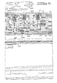
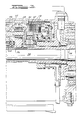
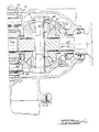
- Figure 1-4 in combination comprise a cross section taken along the axes of the input and output shaft showing various friction clutches and brakes, and several one-way couplings used to produce multiple forward speeds and reverse drive.
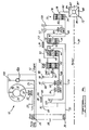
- Figure 5 is a schematic diagram showing planetary gearing, clutches, brakes, couplings, torque converter, chain drive mechanism, final gearing and a differential mechanism.
- Figure 6 is a chart that shows a schedule of engagement and disengagement of clutches, couplings and brakes and to establish the forward drive ratios and reverse drive of the transaxle of Figure 1.
- a hydrokinetic torque converter 10 is driveably connected to an internal combustion engine having a crankshaft 12 connected to a bladed impeller 14 of the torque converter.
- a bladed turbine 16, a bladed stator 18, and the impeller 14 define a toroidal fluid flow circuit within the casing of the torque converter.
- the stator 18 is supported on a stationary sleeve shaft 20, and a overrunning brake 22 anchors the stator to shaft 20 to prevent rotation of stator 18 in a direction opposite to the direction of rotation of the impeller, although free-wheeling motion in the opposite direction is permitted.
- Turbine 16 is connected to turbine sleeve shaft 24, which drives the torque input sprocket wheel 26.
- Sprocket wheel 26 is part of an input torque transfer drive that includes also drive chain 28 and driven sprocket wheel 30, which is mounted for rotation about the torque input sleeve shaft 32.
- Axle shafts 34, 36' are concentric with the axis of input shaft 32.
- Planetary gearing includes three simple planetary gear units.
- the first gear unit includes a sun gear 36, ring gear 38, carrier 40 and planetary pinions 42, supported by carrier 40 in meshing engagement with sun gear 36 and ring gear 38.
- the second planetary gear unit includes a sun gear 44, a ring gear 46, carrier 48 and planet pinions 50, supported by carrier 48 in meshing engagement with sun gear 44 and ring gear 46.
- the third gear unit includes a sun gear 52, a ring gear 54, a carrier 56 and planet pinions 58, supported by carrier 56 in meshing engagement with sun gear 52 and ring gear 54.
- Carrier 48 and ring gear 54 are connected mutually, and they are connected to ring gear 38 by a drum 60, forward clutch 62 and a one-way coupling 64, also identified as OWC2.
- Ring gear 46 is connected to carrier 40 and to torque output shaft 66.
- Sun gears 44, 52 are connected mutually by shaft 68.
- a final drive planetary gearset 70 is located in a torque delivery path between output shaft 66 and a differential gear unit 72, to which axle shafts 34 and 36' are connected.
- Gear unit 70 includes sun gear 74, connected to output shaft 66; ring gear 76, permanently fixed to the transmission casing; a carrier 78, connected to the spindle 80 of the differential mechanism 72; and planet pinions 82, rotatably supported on carrier 78 in engagement with sun gear 74 and ring gear 76.
- Differential gear unit 72 has bevel pinions 84, 85, which mesh with bevel side gears 86, 87, connected respectively to axle shafts 34, 36'.
- Sun gears 44, 52 of the second and third gear units are releasably connectable to the transmission casing through a one-way coupling 92 (OWC3) and a brake 88, which carries also the symbol 4B.
- Sun gears 44, 52 are releasably connected to the casing also through one-way coupling 94 (OWC4) and by a brake 90, which also carries the symbol 2B.
- the outer torsional member of reverse clutch 98 (RC) is connected to drum 96, and the inner member of the reverse clutch is directly connected to input shaft 32 and to the outer member of direct clutch 100 (DC).
- Carrier 48 of the second gear unit is selectively connected to input shaft 32 through direct clutch 100.
- the torque converter includes a lockup clutch 102, located within the torque converter and impeller housing.
- the torque output side of the lockup clutch has a damper 104 located between the impeller and the turbine sleeve shaft 24 so that engagement of the lockup clutch will not be accompanied by harshness due to transitional torque fluctuations.
- the inner race of a one-way or overrunning brake (OWC1) 106 is directly connected to carrier 48 and drum 60; the outer race of brake 106 is fixed permanently against rotation to the transmission casing.
- the inner race of one-way clutch 64 is connected to ring gear 38, and its outer race is connected to one element of forward clutch 62.
- One-way couplings 64, 92, 94 and one-way brake 106 are roller-type overrunning couplings generally having an outer cam with an inclined surface driveably connected to, and released from the inner race by a roller in accordance with the speed of rotation of the inner race relative to the outer race.
- Brake 110 (5B) a friction disc brake, holds carrier 56 against rotation by connecting it to the casing when the brake is engaged and releases carrier 56 when disengaged.
- the inner race of one-way coupling 64 is also connected to an element of coast clutch 108 (CC), the other component of the coast clutch being connected to drum 60.
- CC coast clutch 108
- Friction elements 62, 88, 98, 100, 108, 110 are hydraulically actuated clutches and brakes of the type having multiple friction discs supported rotatably on one member of the friction element and a second set of friction discs interposed between the members of the first friction disc set and supported rotatably on the other member of the friction element.
- the friction element When hydraulic pressure is applied to the friction element, the discs are brought into mutual frictional contact and the friction element transmits torque between its members.
- a spring disengages the discs and the friction element is thereafter unable to transmit torque.
- a low/reverse brake band 112 selectively engages drum 60 in low speed manual and reverse drive conditions.
- Brake band 90, 112 are actuated by hydraulic servos, which contract the corresponding brake band into engagement with the respective drums 60, 96 and release this engagement when the corresponding servo is vented.
- Figure 6 shows a chart indicating the clutches and brakes that are engaged and released selectively to produce each of the various forward drive ratios and the reverse ratio.
- the symbol X is used to identify an engaged clutch or brake
- the symbol O/R is used to designate an overrunning condition for couplings or brakes
- a blank is used with respect to columns entitled "OWC1", “OWC2” and “OWC3” and “OWC4" to indicate a one-way coupling or brake that is neither overrunning nor driving.
- forward clutch 62 In operation with the gear selector in the "D" or "OD" position, to establish automatically the lowest forward speed ratio, forward clutch 62 is applied, one-way clutch 64 drives, and one-way brake 106 drives.
- ring gear 38 When the forward clutch is engaged, ring gear 38 is fixed to the transmission casing against rotation, thereby providing the gearset reaction.
- Engine torque then is transmitted hydrodynamically through the torque converter, and transfer drive chain 28 to sprocket wheel 30, input shaft 32, and sun gear 36.
- Carrier 40 of the first planetary gear unit drives output shaft 66, and the axle shafts 34, 36' are driven through final drive gear set 70 and differential unit 72.
- one-way brake 106 and one-way clutch 64 When operating in the D-range under a coast condition, one-way brake 106 and one-way clutch 64 overrun.
- coast clutch 108 and low reverse band 112 are applied.
- the torque delivery path from ring gear 38 through the coast clutch shunts the torque path that includes one-way coupling 64 and forward clutch 62. Therefore, in the drive condition, there are two parallel paths potentially providing a gearset reaction on the transmission casing to hold ring gear 38 against rotation.
- One path is through one-way coupling 64 and forward clutch 62, and one-way brake 106; the other path is through coast clutch 108 and reverse band 102.
- couplings 64 and 106 are inoperative, and the reaction on the transmission casing that holds ring gear 38 is provided through the coast clutch and the low/reverse band.
- the torque delivery path for the second forward speed in the D-range results when forward clutch 62 and brake band 90 are applied, one-way couplings 64, 94 drive, and one-way brake 106 overruns.
- sun gear 44 is held against rotation on the transmission casing by engagement of brake band 90.
- Torque from the engine is delivered to sun gear 36 and the output is taken at carrier 40, which is connected to output shaft 66.
- the output means comprising output shaft 66, carrier 40 and planet pinions 42 turn as a unit.
- one-way couplings 64, 94, 106 overrun and torque from output shaft 66 is transmitted through carrier 48 to ring gear 46, which is driveably connected by overrunning coupling 64 to input shaft 32.
- one-way coupling 64 drives.
- the engine shaft 12 is driveably connected through the torque converter and chain drive to the input shaft 32, which is connected through direct clutch 100 to intermediate shaft 114, which drives carrier 48, the input member of the second planetary gear unit.
- Carrier 48 is connected through forward clutch 62 and one-way clutch 64 to ring gear 38.
- the third speed ratio is a direct drive ratio; therefore, the output unit, ring gear 46, carrier 40 and output shaft 66, turn at the speed of carrier 48 and ring gear 38.
- coast clutch 108 and drum 60 bypass the torque delivery path that includes forward clutch 62 and one-way coupling 64 to driveably connect ring gear 38 to carrier 48, thereby driving input shaft 32 at the speed of output shaft 66. Engagement of brake 82 assures that one-way coupling 94 overruns.
- the fourth forward speed is available when the gear selector is in the D-range and 4M-range positions.
- friction band 88, forward clutch 62 and direct clutch 100 are applied, one-way coupling 64 and 106 overrun, one-way coupling 94 is inoperative and coupling 92 drives. Consequently, the engine shaft is connected through the torque converter, chain drive mechanism, input shaft 32, direct clutch 100 and intermediate shaft 114 to carrier 48, the input to the planetary gearing.
- Sun gear 44 is fixed against rotation on the transmission housing by engagement of friction brake 88.
- the output is ring gear 46, carrier 40 and output shaft 66, whose speed of rotation is multiplied through this arrangement in the second planetary gear unit only.
- the first gear unit is inoperative, although forward clutch 62 is engaged, because one-way coupling 64 overruns. Engagement of brake band 90 assures that one-way coupling 94 overruns in the drive condition.
- shaft 66 drives carrier 40 and ring gear 46, but sun gear 44 is held against rotation by brake 88. Consequently carrier 48 drives intermediate shaft 114, which is connected to the engine through shaft 32, the direct clutch, and the chain drive mechanism.
- the fifth speed is available only with the gear selector in the D-range. Fifth speed results when brakes 88 and 90, the direct clutch, and forward clutch are engaged. This causes couplings 64, 92, 106 to overrun and holds carrier 56 against rotation.
- Input shaft 32 drives carrier 48 and ring gear 54 through the direct clutch and intermediate shaft.
- Planet pinions 58 counterdrive sun gear 52 and drum 96 through coupling 94 because carrier 58 held.
- Torque carried by compound sun gears 52 and 44 combine in the second gear unit to drive planet pinions 58, which also revolve due to the connection of carrier 48 to the input shaft.
- Ring gear 46 which is driven by carrier 48 and pinions 50, is connected to the output shaft by carrier 40. Ring gear 38 and the inner race of coupling 64 overrun.
Landscapes
- Engineering & Computer Science (AREA)
- General Engineering & Computer Science (AREA)
- Mechanical Engineering (AREA)
- Structure Of Transmissions (AREA)
Description
- The present invention relates to a multiple speed automatic transaxle for an automotive vehicle of the kind as referred to in the preamble of
claim 1 and known from EP-A-037 169. - Various arrangements of clutches, brakes and one-way clutches are used in the prior art to control operation of dual interconnected planetary gear units to produce forward speed ratios and a reverse drive ratio in an automatic transmission.
- U.S. Patent 4,418,585 has clutches and brakes arranged so that a gear ratio change from the lowest speed to the second speed is made nonsynchronously, i.e., by transferring torque from an overrunning coupling to a friction clutch. In that transmission, a gear shift from the second speed to the third speed requires disengagement of the brake band and application of a clutch. A gear ratio change from the third speed to the fourth or overdrive speed also requires disengagement of a brake band and engagement of a friction clutch. In the operation of the transmission, none of the gear shifts require synchronous disengagement of a clutch and engagement of another clutch. Therefore, timing problems in the engagement and release of the clutch brake control servos are eliminated.
- The transmission according to the '585 patent requires time for disengagement of a high speed ratio clutch and application of a friction brake in order to produce the ratio change from the third forward speed to the fourth overdrive speed.
- U.S. Patent 4,368,649 describes a four-speed transaxle that overcomes this difficulty. In the transaxle of the '649 patent the gear shift from the third speed to the fourth speed results by applying a single friction brake in addition to the other friction elements engaged during the third speed ratio. A gear shift from the first speed to the second forward speed results merely by engaging a second friction clutch while a companion friction clutch remains applied. In this way, a ratio change from the first ratio and from the third ratio in the forward driving speed range results merely by engaging or disengaging a single friction element, either a clutch or a brake, thereby greatly simplifying control of the clutches and eliminating potential for harsh or abrupt gear shift changes.
- U.S. Patent 4,509,389 describes a further improvement that eliminates a latent difficulty in control of the transmission of the '649 patent that makes calibration of the two-three upshift difficult. The sun gear is not connected to a friction clutch cylinder but is connected instead to the inner race of an associated one-way clutch. The inner races of each one-way coupling are connected to a common member, which operates as a torque delivery element for the input sun gear of the planetary gear. The maximum speed of the friction clutch cylinders is equal to the speed of the driven sprocket of a chain mechanism connecting the output of a torque converter to the input shaft of the transmission.
- U.S. Patent 4,086,827 describes a four speed transmission in which a single one-way clutch is located in series between an input friction clutch and a gear member of a planetary gear set. The one-way clutch permits the gear member to overrun the input during an overdrive ratio so that an upshift from the third speed to the fourth speed results without a synchronous release of the input friction clutch. To produce a downshift from the fourth speed to the second or third speeds, the input increases to the speed of the gear member by engagement of the one-way clutch when a friction brake or another friction clutch is released.
- The present invention as claimed in
claim 1 provides for five forward speeds and a reverse drive ratio, and is an improvement over the four speed transaxle described in EP-A-037 169. - The present invention is a two-axis transaxle having preferably a hydrokinetic torque converter mounted on an axis concentric with the engine crankshaft and parallel to the axis of the multiple speed gearing. The transaxle produces two underspeed ratios, a direct drive ratio, two overspeed ratios and a reverse drive ratio.
- Because of the unique arrangement of the clutch, brakes and one-way couplings, the transaxle is extremely compact and its weight is low. The compactness of the transaxle is the result of use of certain components of the transaxle for multiple purposes to produce multiple speed ratios. For example, the structure that provides the gearset reaction force through a one-way coupling in intermediate speed ranges, the second and third speed ratios, is used also to transmit torque converter turbine torque in the reverse drive condition.
- The torque path between the engine and the planetary gear in the reverse drive condition is through a reverse friction clutch and a drum that provides a surface engaged by an intermediate brake band and the friction plate of the reverse friction clutch. The use of such drum for multiple purposes eliminates the need for an additional component.
- A one-way coupling, located between the gear units and engine, overruns in the reverse coast condition. The engine is driveably disconnected from the wheels and therefore unavailable to impede vehicle movement. This avoids abrupt unexpected changes in acceleration when the operator changes from drive to coast conditions in the reverse range.
- The transaxle includes three planetary gear units each including a sun gear, a ring gear, a carrier and planetary pinions rotatably supported on the carrier and meshing with the sun gear and ring gear. The carrier of the first gear unit is fixed to the ring gear of the second gear unit and is driveably connected as the output from the gearing to the sun gear of a final drive planetary gearset that drives a differential mechanism.
- The carrier of the second gear unit is connected to the ring gear of the first gear unit and to the inner race of a one-way brake fixed to the transmission casing. The sun gears of the second and third gear units are connected mutually and to two one-way couplings, each coupling fixed to a respective brake. The carrier of the third gear unit is releasably connected to a brake.
- Parallel torque delivery paths between the ring gear of the first planetary gear unit and a low reverse brake drum comprise a one-way coupling and a forward clutch in parallel with a coast clutch, which provides a torque reaction that bypasses the one-way clutch during a coast condition.
- The clutches and brakes of the transaxle are arranged so that the gear ratio change from the lowest speed to the second speed results by transferring torque from a one-way brake to a intermediate brake band. A gear ratio change from the second speed to the third speed results when a direct clutch is engaged and while the brake band continues to be applied. A gear ratio change from the third speed to the fourth speed results by applying an overdrive brake, a friction member, while maintaining engagement of the direct clutch. An upshift to fifth speed from fourth speed result by engaging a fifth speed brake while maintaining engaged the friction elements that produce fourth speed. Therefore, no ratio change requires synchronous disengagement of a friction element and application of another friction element. Because of this feature, timing problems in the engagement and release of friction clutches and brakes and control servos are eliminated.
- Figure 1-4 in combination comprise a cross section taken along the axes of the input and output shaft showing various friction clutches and brakes, and several one-way couplings used to produce multiple forward speeds and reverse drive.
- Figure 5 is a schematic diagram showing planetary gearing, clutches, brakes, couplings, torque converter, chain drive mechanism, final gearing and a differential mechanism.
- Figure 6 is a chart that shows a schedule of engagement and disengagement of clutches, couplings and brakes and to establish the forward drive ratios and reverse drive of the transaxle of Figure 1.
- Referring first to Figures 1-5, a
hydrokinetic torque converter 10 is driveably connected to an internal combustion engine having acrankshaft 12 connected to abladed impeller 14 of the torque converter. Abladed turbine 16, abladed stator 18, and theimpeller 14 define a toroidal fluid flow circuit within the casing of the torque converter. Thestator 18 is supported on astationary sleeve shaft 20, and aoverrunning brake 22 anchors the stator toshaft 20 to prevent rotation ofstator 18 in a direction opposite to the direction of rotation of the impeller, although free-wheeling motion in the opposite direction is permitted. - Turbine 16 is connected to
turbine sleeve shaft 24, which drives the torqueinput sprocket wheel 26.Sprocket wheel 26 is part of an input torque transfer drive that includes alsodrive chain 28 and drivensprocket wheel 30, which is mounted for rotation about the torqueinput sleeve shaft 32.Axle shafts 34, 36' are concentric with the axis ofinput shaft 32. - Planetary gearing includes three simple planetary gear units. The first gear unit includes a
sun gear 36,ring gear 38,carrier 40 andplanetary pinions 42, supported bycarrier 40 in meshing engagement withsun gear 36 andring gear 38. The second planetary gear unit includes asun gear 44, aring gear 46,carrier 48 andplanet pinions 50, supported bycarrier 48 in meshing engagement withsun gear 44 andring gear 46. The third gear unit includes asun gear 52, aring gear 54, acarrier 56 andplanet pinions 58, supported bycarrier 56 in meshing engagement withsun gear 52 andring gear 54.Carrier 48 andring gear 54 are connected mutually, and they are connected toring gear 38 by adrum 60,forward clutch 62 and a one-way coupling 64, also identified as OWC2.Ring gear 46 is connected tocarrier 40 and totorque output shaft 66. Sungears shaft 68. - A final drive
planetary gearset 70 is located in a torque delivery path betweenoutput shaft 66 and adifferential gear unit 72, to whichaxle shafts 34 and 36' are connected.Gear unit 70 includessun gear 74, connected tooutput shaft 66;ring gear 76, permanently fixed to the transmission casing; acarrier 78, connected to thespindle 80 of thedifferential mechanism 72; andplanet pinions 82, rotatably supported oncarrier 78 in engagement withsun gear 74 andring gear 76.Differential gear unit 72 hasbevel pinions bevel side gears axle shafts 34, 36'. -
Sprocket wheel 30, connected tosleeve shaft 32, is connected directly tosun gear 36 of the first planetary gear unit. Sungears brake 88, which carries also the symbol 4B. Sun gears 44, 52 are releasably connected to the casing also through one-way coupling 94 (OWC4) and by abrake 90, which also carries thesymbol 2B. The inner races of one-way couplings sleeve shaft 68 to sun gears 44, 52; the outer races ofcouplings drum 96, which is connected to the transmission casing through operation ofbrake 90 and to brake 88. - The outer torsional member of reverse clutch 98 (RC) is connected to drum 96, and the inner member of the reverse clutch is directly connected to input
shaft 32 and to the outer member of direct clutch 100 (DC).Carrier 48 of the second gear unit is selectively connected to inputshaft 32 throughdirect clutch 100. - The torque converter includes a
lockup clutch 102, located within the torque converter and impeller housing. The torque output side of the lockup clutch has adamper 104 located between the impeller and theturbine sleeve shaft 24 so that engagement of the lockup clutch will not be accompanied by harshness due to transitional torque fluctuations. - The inner race of a one-way or overrunning brake (OWC1) 106 is directly connected to
carrier 48 anddrum 60; the outer race ofbrake 106 is fixed permanently against rotation to the transmission casing. The inner race of one-way clutch 64 is connected to ringgear 38, and its outer race is connected to one element offorward clutch 62. One-way couplings way brake 106 are roller-type overrunning couplings generally having an outer cam with an inclined surface driveably connected to, and released from the inner race by a roller in accordance with the speed of rotation of the inner race relative to the outer race. Brake 110 (5B), a friction disc brake, holdscarrier 56 against rotation by connecting it to the casing when the brake is engaged andreleases carrier 56 when disengaged. - The inner race of one-
way coupling 64 is also connected to an element of coast clutch 108 (CC), the other component of the coast clutch being connected to drum 60. -
Friction elements - A low/
reverse brake band 112 selectively engagesdrum 60 in low speed manual and reverse drive conditions.Brake band respective drums - Figure 6 shows a chart indicating the clutches and brakes that are engaged and released selectively to produce each of the various forward drive ratios and the reverse ratio. In the chart, the symbol X is used to identify an engaged clutch or brake, the symbol O/R is used to designate an overrunning condition for couplings or brakes, and a blank is used with respect to columns entitled "OWC1", "OWC2" and "OWC3" and "OWC4" to indicate a one-way coupling or brake that is neither overrunning nor driving.
- In operation with the gear selector in the "D" or "OD" position, to establish automatically the lowest forward speed ratio, forward clutch 62 is applied, one-way clutch 64 drives, and one-
way brake 106 drives. When the forward clutch is engaged,ring gear 38 is fixed to the transmission casing against rotation, thereby providing the gearset reaction. Engine torque then is transmitted hydrodynamically through the torque converter, and transferdrive chain 28 tosprocket wheel 30,input shaft 32, andsun gear 36.Carrier 40 of the first planetary gear unit drivesoutput shaft 66, and theaxle shafts 34, 36' are driven through final drive gear set 70 anddifferential unit 72. When operating in the D-range under a coast condition, one-way brake 106 and one-way clutch 64 overrun. - When first gear is selected manually by the operator by placing the gear shift lever in the 1M-range position,
coast clutch 108 and lowreverse band 112 are applied. The torque delivery path fromring gear 38 through the coast clutch shunts the torque path that includes one-way coupling 64 and forward clutch 62. Therefore, in the drive condition, there are two parallel paths potentially providing a gearset reaction on the transmission casing to holdring gear 38 against rotation. One path is through one-way coupling 64 and forward clutch 62, and one-way brake 106; the other path is throughcoast clutch 108 andreverse band 102. However, in the coast condition,couplings ring gear 38 is provided through the coast clutch and the low/reverse band. - The torque delivery path for the second forward speed in the D-range results when forward clutch 62 and
brake band 90 are applied, one-way couplings way brake 106 overruns. In this instance,sun gear 44 is held against rotation on the transmission casing by engagement ofbrake band 90. Torque from the engine is delivered tosun gear 36 and the output is taken atcarrier 40, which is connected tooutput shaft 66. In the coast condition, all one-way couplings output shaft 66,carrier 40 and planet pinions 42 turn as a unit. - When the gear selector is set manually for operation in the 2M-range,
coast clutch 108, forward clutch 62,friction brake 88 andbrake band 90 are applied. During the drive condition in the 2M-range, one-way couplings way brake 106 overruns. In this instance,sun gear 44 is fixed against rotation on the transmission housing by engagement of thebrake band 90, andring gear 38 is driveably connected tocarrier 48 of the second planetary gear unit through either the torque delivery path that includes coast clutch 108 or the parallel path that includes one-way coupling 64 and forward clutch 62. In the coast condition in the 2M-range, one-way brake 106 overruns and one-way couplings Sun gear 44 is fixed to the transmission casing against rotation bybrake 88.Ring gear 38 is connected tocarrier 48 of the first planetary gear unit through the path that includescoast clutch 108 anddrum 60.Sun gear 36 drivesinput shaft 32. - When the transmission operates in the third forward speed and the gear selector is in the D-range, where gearshifts are produced automatically, forward clutch 62 and
brake band 90 remain engaged,direct clutch 100 is engaged and one-way coupling 62 drives. Torque input from the engine is directed through the direct clutch andintermediate shaft 102, arranged concentrically withinput shaft 32 andaxle shaft 34, tocarrier 48 of the second planetary gear unit.Carrier 48drives ring gear 36 throughdrum 60, forward clutch 62 and one-way coupling 64. The torque output is taken bycarrier 40 tooutput shaft 66. - During a coast condition in the third forward speed of the D-range, one-
way couplings output shaft 66 is transmitted throughcarrier 48 toring gear 46, which is driveably connected by overrunningcoupling 64 to inputshaft 32. - With the transmission operating in the 3M-range forward clutch 62,
coast clutch 108,direct clutch 100 andbrake band 90 are applied. During a drive condition in that range, one-way coupling 64 drives. With the friction elements so engaged, theengine shaft 12 is driveably connected through the torque converter and chain drive to theinput shaft 32, which is connected through direct clutch 100 to intermediate shaft 114, which drivescarrier 48, the input member of the second planetary gear unit.Carrier 48 is connected through forward clutch 62 and one-way clutch 64 to ringgear 38. The third speed ratio is a direct drive ratio; therefore, the output unit,ring gear 46,carrier 40 andoutput shaft 66, turn at the speed ofcarrier 48 andring gear 38. During a coast condition in the 3M-range, one-way couplings couplings coast clutch 108 and drum 60 bypass the torque delivery path that includes forward clutch 62 and one-way coupling 64 to driveably connectring gear 38 tocarrier 48, thereby drivinginput shaft 32 at the speed ofoutput shaft 66. Engagement ofbrake 82 assures that one-way coupling 94 overruns. - The fourth forward speed, an overdrive ratio, is available when the gear selector is in the D-range and 4M-range positions. To produce the fourth speed ratio in the D-range,
friction band 88, forward clutch 62 anddirect clutch 100 are applied, one-way coupling way coupling 94 is inoperative andcoupling 92 drives. Consequently, the engine shaft is connected through the torque converter, chain drive mechanism,input shaft 32,direct clutch 100 and intermediate shaft 114 tocarrier 48, the input to the planetary gearing.Sun gear 44 is fixed against rotation on the transmission housing by engagement offriction brake 88. The output isring gear 46,carrier 40 andoutput shaft 66, whose speed of rotation is multiplied through this arrangement in the second planetary gear unit only. The first gear unit is inoperative, although forward clutch 62 is engaged, because one-way coupling 64 overruns. Engagement ofbrake band 90 assures that one-way coupling 94 overruns in the drive condition. - During the fourth speed coast condition in the D-range, one-
way couplings Sun gear 44 is held against rotation bybrake 88, andshaft 66drives carrier 40 andring gear 46.Carrier 48 is driveably connected to thesprocket wheel 30 of the chain drive mechanism through intermediate shaft 114,direct clutch 100 andinput shaft 32. - During operation in the 4M-range,
brake 88,direct clutch 100, and forward clutch 62 are engaged.Couplings coupling 92 drives. Consequently, under drive conditions,sun gear 44 produces the gearset reaction because it is held on the casing throughcoupling 92 by engagement ofbrake 88.Carrier 48 is driven, but because coupling 64 overruns, the output is taken atring gear 46,carrier 40 andshaft 66. - Under coast conditions in the 4M-range,
shaft 66drives carrier 40 andring gear 46, butsun gear 44 is held against rotation bybrake 88. Consequentlycarrier 48 drives intermediate shaft 114, which is connected to the engine throughshaft 32, the direct clutch, and the chain drive mechanism. - The fifth speed is available only with the gear selector in the D-range. Fifth speed results when
brakes couplings carrier 56 against rotation.Input shaft 32drives carrier 48 andring gear 54 through the direct clutch and intermediate shaft. Planet pinions 58counterdrive sun gear 52 anddrum 96 throughcoupling 94 becausecarrier 58 held. Torque carried by compound sun gears 52 and 44 combine in the second gear unit to drive planet pinions 58, which also revolve due to the connection ofcarrier 48 to the input shaft.Ring gear 46, which is driven bycarrier 48 andpinions 50, is connected to the output shaft bycarrier 40.Ring gear 38 and the inner race ofcoupling 64 overrun. - When the transmission is disposed for reverse drive operation,
input shaft 32 is driveably connected through reverse clutch 98,drum 96, one-way coupling 94 andsleeve shaft 68 to compound sun gears 52 and 44, the input to the second planetary gear unit.Carrier 48 is fixed against rotation through engagement of low/reverse brake band 112. As a result of this engagement,ring gear 46 is counterrotated and the output is taken oncarrier 40 andoutput shaft 66. During the coast condition in the R-range, coupling 94 overruns, thereby driveably disconnecting sun gears 44 and 52 frominput shaft 32 and from the engine.
Claims (5)
- A multiple speed automatic transaxle for an automotive vehicle having a power source for driving a load, comprising:- input means (10, 32) for carrying torque between the power source and a planetary gear system;- output means (34, 36', 66, 70, 72) for carrying torque between the planetary gear system and the load;- said planetary gear system comprising first, second and third planetary gear units, each gear unit having a sun gear (36, 44, 52), a ring gear (38, 46, 54), planet pinions (42, 50, 56) meshing with the sun and ring gears, and a carrier (40, 48, 56) rotatably supporting the planet pinions, the sun gears (44, 52) of the second and third gear units being connected mutually, the carrier (48) of the second gear unit being permanently connected to the ring gear (54) of the third gear unit, the input means (10, 32) being connected to the sun gear (36) of the first gear unit, and the output means (34, 36', 66, 70, 72) being connected to one element (46) of the second gear unit and to the carrier (40) of the first gear unit; and- clutch and brake means to produce multiple forward speed ratios and a reverse drive ratio in a timed relationship;characterized by- first clutch means for delivering torque between the ring gear (38) of the first gear unit and the carrier (48) of the second gear unit the ring gear (46) of which being connected to the output means (34, 36', 66, 70, 72), said first clutch means comprising a first over-running coupling (OWC2/64) and a first friction clutch (62) disposed in series with the first overrunning coupling;- first overrunning brake means (OWC1/106) for holding the carrier (48) of the second gear unit and the ring gear (54) of the third gear unit against rotation in one rotary direction and releasing said carrier (48) and said ring gear (54) in the opposite rotary direction;- second clutch means (100) for delivering torque between the input means (10, 32) and the carrier (48) of the second gear unit;- third clutch means for delivering torque between the input means (10, 32) and the sun gears (44, 52) of the second and third gear units, said third clutch means comprising a second overrunning coupling (OWC4/94) and a third friction clutch (98) disposed in series with said second overrunning coupling;- first brake means (90) for releasably holding the sun gears (44, 52) of the second and third gear units against rotation;- second brake means (112) for releasably holding the carrier (48) of the second gear unit against rotation;- first overdrive brake means for holding against rotation and releasing the sun gears (44, 52) of the second and third gear units, said first overdrive brake means comprising a first friction brake (88) having an output fixed to the transmission casing and a third overrunning coupling (OWC3/92) for producing a one-way drive connection between the sun gears (44, 52) of the second and third gear units and said first friction brake (88);- second overdrive brake means (110) for holding against rotation and releasing the carrier (56) of the third gear unit; and- coast clutch means (108) disposed in parallel with the first clutch means (OWC2/64, 62) between the ring gear (38) of the first gear unit and the carrier (48) of the second gear unit.
- A multiple speed automatic transaxle according to claim 1, wherein a first drum (60) is driveably connected to the carrier (48) of the second gear unit and the ring gear (54) of the third gear unit, said first drum cooperating with said first clutch means (OWC2/64, 62), said first overrunning brake means (OWC1/106) and said second brake means (112); and a second drum (96) is driveably connected to the sun gears (44, 52) of the second and third gear units, said second drum cooperating with said first overdrive brake means (OWC3/92, 88), said third clutch means (OWC4/94, 98) and said first brake means (90), the third friction clutch (98) releasably connecting the second drum and the input means (10, 32).
- A multiple speed automatic transaxle according to claim 1 or claim 2, wherein said input means comprises a hydrokinetic torque converter (10) having an impeller (14) driveably connected to the power source and a turbine (16) hydrokinetically coupled to said impeller, the impeller being driveably connected to a torque input sleeve shaft (32).
- A multiple speed automatic transaxle according to any of the claims 1 to 3, wherein said output means (34, 36', 66, 70, 72) comprises a final drive gearing (70) driveably connecting the output of the planetary gear system and the load.
- A multiple speed automatic transaxle according to any of the claims 3 to 4, wherein the torque carrying path further includes a torque transfer drive comprising a drive sprocket (26) connected to said turbine (16), a driven sprocket (30) connected to said torque input sleeve shaft (32) and a drive chain (28) driveably connecting said drive and driven sprockets.
Applications Claiming Priority (2)
| Application Number | Priority Date | Filing Date | Title |
|---|---|---|---|
| US755939 | 1991-09-06 | ||
| US07/755,939 US5131902A (en) | 1991-09-06 | 1991-09-06 | Nonsynchronous five-speed transaxle for automotive vehicles |
Publications (3)
| Publication Number | Publication Date |
|---|---|
| EP0530516A2 EP0530516A2 (en) | 1993-03-10 |
| EP0530516A3 EP0530516A3 (en) | 1993-09-08 |
| EP0530516B1 true EP0530516B1 (en) | 1996-11-13 |
Family
ID=25041332
Family Applications (1)
| Application Number | Title | Priority Date | Filing Date |
|---|---|---|---|
| EP92113217A Expired - Lifetime EP0530516B1 (en) | 1991-09-06 | 1992-08-03 | Multiple speed automatic transaxle for automotive vehicles |
Country Status (3)
| Country | Link |
|---|---|
| US (1) | US5131902A (en) |
| EP (1) | EP0530516B1 (en) |
| DE (1) | DE69215167T2 (en) |
Families Citing this family (7)
| Publication number | Priority date | Publication date | Assignee | Title |
|---|---|---|---|---|
| US5295924A (en) * | 1992-12-07 | 1994-03-22 | Ford Motor Company | Multiple speed nonsynchronous automatic transmission for motor vehicles |
| KR100302789B1 (en) * | 1994-08-18 | 2001-11-22 | 이계안 | Power train of car automatic transmission |
| KR0145492B1 (en) * | 1994-10-03 | 1998-08-01 | 와다 아키히로 | Gear transmission for automatic transmission |
| US5642283A (en) * | 1995-10-27 | 1997-06-24 | Ford Motor Company | Multiple ratio transmission with swap-shift controls |
| JP3108642B2 (en) * | 1996-12-05 | 2000-11-13 | アイシン・エィ・ダブリュ株式会社 | Automatic transmission |
| US7448977B2 (en) * | 2005-10-21 | 2008-11-11 | Ford Global Technologies, Llc | Motor vehicle transaxle having a differential mechanism controlled by an on-demand clutch |
| US9051980B2 (en) | 2013-04-26 | 2015-06-09 | Gm Global Technology Operations, Llc | Direction selectable sprag |
Family Cites Families (17)
| Publication number | Priority date | Publication date | Assignee | Title |
|---|---|---|---|---|
| US3523468A (en) * | 1968-11-04 | 1970-08-11 | Ford Motor Co | Four speed ratio planetary gear mechanism |
| US3705521A (en) * | 1968-12-20 | 1972-12-12 | Gen Motors Corp | Dual path power transmission |
| US3811343A (en) * | 1969-06-04 | 1974-05-21 | Nissan Motor | Gear train arrangements |
| US3946622A (en) * | 1973-02-26 | 1976-03-30 | Aisin Seiki Kabushiki Kaisha | Speed change gear |
| GB1483727A (en) * | 1973-08-17 | 1977-08-24 | Volvo Ab | Compound epicyclic transmission systems |
| US3862581A (en) * | 1974-02-04 | 1975-01-28 | Gen Motors Corp | Four speed transmission |
| US4086827A (en) * | 1975-08-21 | 1978-05-02 | General Motors Corporation | Four-speed transmission |
| JPS5250458A (en) * | 1975-10-20 | 1977-04-22 | Nissan Motor Co Ltd | Planetary type shifting transmission |
| US4318311A (en) * | 1980-03-31 | 1982-03-09 | General Motors Corporation | Centrifugally actuated valve for transmission |
| US4418585A (en) * | 1980-04-21 | 1983-12-06 | Ford Motor Company | Four speed ratio transverse automatic transmission |
| US4368649A (en) * | 1980-07-01 | 1983-01-18 | Ford Motor Company | Automatic transaxle driveline having four forward driving ratios and a single reverse ratio |
| GB2107008B (en) * | 1981-07-28 | 1985-06-05 | Volvo Ab | Multi-ratio power transmissions |
| JPS61192953A (en) * | 1985-02-21 | 1986-08-27 | Nissan Motor Co Ltd | Planet gear train of automatic transmission |
| US4683776A (en) * | 1986-02-27 | 1987-08-04 | General Motors Corporation | Transmission gearing arrangement |
| US4884471A (en) * | 1988-06-23 | 1989-12-05 | Ford Motor Company | Four speed ratio automatic power transmission |
| JPH0235243A (en) * | 1988-07-21 | 1990-02-05 | Toyota Motor Corp | Transmission gear for automatic transmission |
| US5129871A (en) * | 1991-10-07 | 1992-07-14 | Ford Motor Company | Nonsynchronous five-speed transaxle having bidirectional coupling |
-
1991
- 1991-09-06 US US07/755,939 patent/US5131902A/en not_active Expired - Fee Related
-
1992
- 1992-08-03 DE DE69215167T patent/DE69215167T2/en not_active Expired - Fee Related
- 1992-08-03 EP EP92113217A patent/EP0530516B1/en not_active Expired - Lifetime
Also Published As
| Publication number | Publication date |
|---|---|
| EP0530516A3 (en) | 1993-09-08 |
| DE69215167D1 (en) | 1996-12-19 |
| DE69215167T2 (en) | 1997-06-12 |
| EP0530516A2 (en) | 1993-03-10 |
| US5131902A (en) | 1992-07-21 |
Similar Documents
| Publication | Publication Date | Title |
|---|---|---|
| US5435792A (en) | Multiple-speed automatic transmission for motor vehicles | |
| US5295924A (en) | Multiple speed nonsynchronous automatic transmission for motor vehicles | |
| EP0569157B1 (en) | Multiple speed synchronous automatic transmission for motor vehicles | |
| EP0719961B1 (en) | Multiple-speed automatic transmission for a motor vehicle | |
| US5429557A (en) | Multiple-speed automatic transaxle for automotive vehicles | |
| US5823051A (en) | Multi-speed power transmission | |
| US5692988A (en) | Multiple-speed automatic transmission for an automotive vehicle | |
| US5267916A (en) | Multiple speed automatic transmission for automotive vehicles | |
| GB2036896A (en) | Power transmission mechanism | |
| US5129871A (en) | Nonsynchronous five-speed transaxle having bidirectional coupling | |
| EP0038538B1 (en) | Four speed ratio transverse automatic transmission | |
| US6007450A (en) | Five speed planetary transmission | |
| US5755636A (en) | Multiple-speed automatic transmission for an automotive vehicle | |
| US5167593A (en) | Nonsynchronous four-speed transaxle for automotive vehicles | |
| US5503605A (en) | Multiple speed automatic transaxle for automotive vehicles | |
| US6908408B2 (en) | Multiple-speed power transmission for motor vehicles | |
| EP0719960B1 (en) | Multiple-Speed automatic transmission for motor vehicles | |
| US5267913A (en) | Multiple speed automatic transmission for automotive vehicles | |
| GB2031075A (en) | Transmission mechanism | |
| US5716298A (en) | Multiple-speed automatic transmission for an automotive vehicle | |
| EP0530516B1 (en) | Multiple speed automatic transaxle for automotive vehicles | |
| US5961414A (en) | Dual mode continuously variable transmission having multiple torque input paths | |
| EP0676562B1 (en) | Gear train of an automatic five-speed transmission for a vehicle | |
| US5261861A (en) | Five-speed transaxle for automotive vehicles | |
| US6146305A (en) | Six speed planetary transmission with two simple planetary gear sets |
Legal Events
| Date | Code | Title | Description |
|---|---|---|---|
| PUAI | Public reference made under article 153(3) epc to a published international application that has entered the european phase |
Free format text: ORIGINAL CODE: 0009012 |
|
| AK | Designated contracting states |
Kind code of ref document: A2 Designated state(s): DE FR GB |
|
| PUAL | Search report despatched |
Free format text: ORIGINAL CODE: 0009013 |
|
| AK | Designated contracting states |
Kind code of ref document: A3 Designated state(s): DE FR GB |
|
| 17P | Request for examination filed |
Effective date: 19940110 |
|
| 17Q | First examination report despatched |
Effective date: 19950301 |
|
| GRAG | Despatch of communication of intention to grant |
Free format text: ORIGINAL CODE: EPIDOS AGRA |
|
| GRAH | Despatch of communication of intention to grant a patent |
Free format text: ORIGINAL CODE: EPIDOS IGRA |
|
| GRAH | Despatch of communication of intention to grant a patent |
Free format text: ORIGINAL CODE: EPIDOS IGRA |
|
| GRAA | (expected) grant |
Free format text: ORIGINAL CODE: 0009210 |
|
| AK | Designated contracting states |
Kind code of ref document: B1 Designated state(s): DE FR GB |
|
| REF | Corresponds to: |
Ref document number: 69215167 Country of ref document: DE Date of ref document: 19961219 |
|
| ET | Fr: translation filed | ||
| ET | Fr: translation filed |
Free format text: CORRECTIONS |
|
| PLBE | No opposition filed within time limit |
Free format text: ORIGINAL CODE: 0009261 |
|
| STAA | Information on the status of an ep patent application or granted ep patent |
Free format text: STATUS: NO OPPOSITION FILED WITHIN TIME LIMIT |
|
| 26N | No opposition filed | ||
| PGFP | Annual fee paid to national office [announced via postgrant information from national office to epo] |
Ref country code: GB Payment date: 19980720 Year of fee payment: 7 |
|
| PGFP | Annual fee paid to national office [announced via postgrant information from national office to epo] |
Ref country code: FR Payment date: 19980820 Year of fee payment: 7 |
|
| PGFP | Annual fee paid to national office [announced via postgrant information from national office to epo] |
Ref country code: DE Payment date: 19990318 Year of fee payment: 7 |
|
| PG25 | Lapsed in a contracting state [announced via postgrant information from national office to epo] |
Ref country code: GB Free format text: LAPSE BECAUSE OF NON-PAYMENT OF DUE FEES Effective date: 19990803 |
|
| GBPC | Gb: european patent ceased through non-payment of renewal fee |
Effective date: 19990803 |
|
| PG25 | Lapsed in a contracting state [announced via postgrant information from national office to epo] |
Ref country code: FR Free format text: LAPSE BECAUSE OF NON-PAYMENT OF DUE FEES Effective date: 20000428 |
|
| PG25 | Lapsed in a contracting state [announced via postgrant information from national office to epo] |
Ref country code: DE Free format text: LAPSE BECAUSE OF NON-PAYMENT OF DUE FEES Effective date: 20000601 |
|
| REG | Reference to a national code |
Ref country code: FR Ref legal event code: ST |