EP0529144A1 - Far-end echo canceller - Google Patents
Far-end echo canceller Download PDFInfo
- Publication number
- EP0529144A1 EP0529144A1 EP91114911A EP91114911A EP0529144A1 EP 0529144 A1 EP0529144 A1 EP 0529144A1 EP 91114911 A EP91114911 A EP 91114911A EP 91114911 A EP91114911 A EP 91114911A EP 0529144 A1 EP0529144 A1 EP 0529144A1
- Authority
- EP
- European Patent Office
- Prior art keywords
- far
- end echo
- signal
- data symbols
- phase
- Prior art date
- Legal status (The legal status is an assumption and is not a legal conclusion. Google has not performed a legal analysis and makes no representation as to the accuracy of the status listed.)
- Granted
Links
- 238000007493 shaping process Methods 0.000 claims abstract description 15
- 238000004891 communication Methods 0.000 claims description 20
- 230000003044 adaptive effect Effects 0.000 claims description 2
- 238000001914 filtration Methods 0.000 claims 5
- 238000000034 method Methods 0.000 claims 1
- 238000002592 echocardiography Methods 0.000 description 4
- 238000004088 simulation Methods 0.000 description 3
- 238000010276 construction Methods 0.000 description 2
- 230000008878 coupling Effects 0.000 description 2
- 238000010168 coupling process Methods 0.000 description 2
- 238000005859 coupling reaction Methods 0.000 description 2
- 230000005540 biological transmission Effects 0.000 description 1
- 238000005070 sampling Methods 0.000 description 1
- 238000001228 spectrum Methods 0.000 description 1
Images


Classifications
-
- H—ELECTRICITY
- H04—ELECTRIC COMMUNICATION TECHNIQUE
- H04B—TRANSMISSION
- H04B3/00—Line transmission systems
- H04B3/02—Details
- H04B3/20—Reducing echo effects or singing; Opening or closing transmitting path; Conditioning for transmission in one direction or the other
- H04B3/23—Reducing echo effects or singing; Opening or closing transmitting path; Conditioning for transmission in one direction or the other using a replica of transmitted signal in the time domain, e.g. echo cancellers
- H04B3/232—Reducing echo effects or singing; Opening or closing transmitting path; Conditioning for transmission in one direction or the other using a replica of transmitted signal in the time domain, e.g. echo cancellers using phase shift, phase roll or frequency offset correction
Definitions
- the present invention relates to a data transmission system including an echo canceller. More particularly, the present invention relates to a far-end echo canceller for use in a system in which the far-end echo contains a frequency offset.
- a local terminal simultaneously transmits data to and receives data from a remote terminal via a communication channel which is formed at least in part by a two-wire telephone line.
- a hybrid coupler is located at each end of the channel for the purpose of isolating the incoming and outgoing signals. Because the hybrid couplers operate imperfectly, the outgoing signal of the local terminal may be partially reflected at the local hybrid coupler in the form of a near-end echo and partially reflected at the remote hybrid coupler in the form of a far-end echo. Both echoes corrupt the incoming signal of the local terminal.
- the near-end echo is generally identical in carrier frequency to the local outgoing signal. It can therefore be eliminated easily by a conventional near-end echo canceller.
- the near-end echo canceller comprises an adaptive linear transversal filter that simulates the transfer function of the near-end echo path that produced the near-end echo.
- the outgoing signal is processed by the near-end echo canceller to generate a simulated near-end echo signal.
- the simulated near-end echo signal is then subtracted from the incoming signal which is corrupted with the near-end echo.
- the far-end echo may have a continually shifting phase, for example, in the form of a frequency offset, relative to the original outgoing signal. This may be caused by small differences between the carrier frequency of the outgoing signal and the carrier frequency of the far-end echo signal that occur when circuits used to step up and step down the signal carrier frequency are not perfectly matched. This is the case when the communications channel between the local data terminal and the remote data terminal includes a satellite hop. Because of the non-linearity in the far-end echo transfer function as represented by the changing phase, a far-end echo canceller in the form of a linear transversal filter is unable to adequately simulate the far-end echo transfer function (see, e.g., Ling, U.S. Patent 4,813,073).
- a conventional far-end echo canceller for simulating a far-end echo path comprises four transversal filters, followed by two summers, followed by two multipliers, followed by another summer.
- QAM Quadrature Amplitude Modulation
- a far-end echo path may be simulated at a terminal which utilizes QAM by processing the in-phase and quadrature data symbols by a pulse shaping filter whose transfer function is, for example, a raised cosine function.
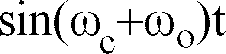
- the in-phase and quadrature data symbol are then multiplied by cos( ⁇ c + ⁇ o )t and sin( ⁇ c + ⁇ o )t , respectively, where ⁇ c is the carrier frequency utilized by the QAM and ⁇ o is the offset frequency which is determined by a phase lock loop adaptively.
- the output signals from the multipliers are then summed using a summer and the summed signal is then processed by a transversal filter having a real transfer function which is adaptively determined.
- the output of this filter is a simulated far-end echo signal.
- the echo canceller may be implemented using only two multipliers, one summer and one transversal filter. This is much simpler than the conventional far-end echo canceller described above.
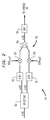
- FIG 1 schematically illustrates a communication system including a far-end echo canceller.
- FIG 2 schematically illustrates a transmitter for use in the communication system of FIG 1.
- FIG 3 illustrates a conventional far-end echo canceller for use in the communication system of FIG 1.
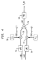
- FIG 4 illustrates a far-end echo canceller for use in the system of FIG 1, in accordance with an embodiment of the present invention.
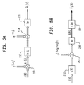
- FIG 5A and FIG 5B explain the mathematical relationship between the echo cancellers of FIG 3 and FIG 4.
- FIG 1 schematically illustrates a communication system 1.
- the system comprises a local terminal 10 and a remote terminal 10'.
- the local terminal 10 transmits data to and receives data from the remote terminal 10' via communications channel 12.
- the channel 12 is formed in part by a two-wire telephone line. However, portions of the channel 12 may be formed by other communications media such as a satellite hop.
- Data symbols to be transmitted from the terminal 10 arrive at a transmitter 14 via line 11.
- the data symbols are modulated into a carrier using, for example, Quadrature Amplitude Modulation.
- the modulated carrier signal is then routed to a hybrid coupler 16 via line 17.
- the hybrid coupler 16 routes the modulated carrier signal to a two wire line 13 which forms part of the communications channel 12.
- a transmitter 14' receives data symbols via line 11' and modulates the symbols onto a carrier.
- the modulated carrier is then delivered to a hybrid coupler 16' via line 17'.
- the hybrid coupler 16' then routes the modulated carrier signal onto a two-wire line 13' which forms part of the channel 12.
- the two-wire lines 13 and 13' each carry both an outgoing modulated signal and an incoming modulated signal.
- the hybrid 16 routes the incoming signal on the two-wire line 13 to the summers 18 and 19 and the receiver 22 via the line 27.
- the hybrid 16' routes the incoming signal on the two-wire line 13' to the summers 18' and 19' and the receiver 22' via the line 27'.
- the summers 18, 19 and 18', 19' are utilized for echo cancellation in a manner described below.
- the receivers 22 and 22' demodulate the received modulated carrier signal to provide output data symbols on the lines 31 and 31', respectively.
- the incoming modulated signal on the line 27 in the terminal 10 comprises the incoming signal s(k) generated by the transmitter 14' in the terminal 10', a near-end echo e n (k) generated by the hybrid 16 imperfectly coupling the signal generated by the transmitter 14 to the two-wire line 13, and a far-end echo e f (k) resulting from imperfect coupling of the incoming signal on the two-wire line 13' by the hybrid 16' into the line 27'.
- the terminal 10 includes a near-end echo canceller 20 and a far-end echo canceller 30.
- the near-end echo canceller 20 generates a signal ê n (k) which is a simulation of the near-end echo signal e n (k).
- the far-end echo canceller 30 generates a signal ê f (k) which is a simulation of the far-end echo signal e f (k).
- the summer 19 is utilized to subtract ê n (k) from y(k) to produce the signal s(k) on line 28.
- the remote terminal 10' also includes a far-end echo canceller 30' which is identical to the far-end echo canceller 30 and a near-end echo canceller 20' which is identical to the near-end echo canceller 20.
- the near-end echo canceller 20 comprises a linear transversal filter that simulates the transfer function of the near-end echo path. Cancelling the far-end echo is not as simple because the far-end echo has a frequency offset.
- FIG 2 illustrates the transmitter 14 in greater detail.
- the transmitter 14 utilizes Quadrature Amplitude Modulation (QAM).
- QAM Quadrature Amplitude Modulation
- the transmitter 14 receives a sequence of symbols x(k) to be transmitted at the splitter 50.
- the splitter 50 separates the symbols x(k) into in-phase symbols a(k) and quadrature symbols b(k).
- the symbols a(k) and b(k) are then processed by pulse shaping filters 51 with the transfer function g(k).
- the filters g(k) are pulse shaping filters which are utilized to limit the frequency spectrum in the frequency domain and to reduce intersymbol interference in the time domain.
- the transfer function g(k) is a raised cosine function.
- the QAM modulator 52 comprises two multipliers 53 and one summer 54.
- the symbol x(k) is transmitted to the pass-band filters 55 and then to the hybrid 16.
- the pulse shaping filters 51 may be located following the modulator 52 and before the pass-band filter 55.
- an analog-digital converter (not shown) may be included in the transmitter before the pass-band filter 55.
- FIG 3. A conventional circuit for simulating the far-end echo path is shown in FIG 3.
- This circuit comprises three stages, a first rotator stage 60, a set of cross-coupled transversal filters 70, and a post rotator stage 80.
- the rotator stage 60 receives the quadrature and in-phase data symbols a(k),b(k) and outputs the symbols a'(k), b'(k).
- the rotator 60 comprises four multipliers 62 for multiplying a(k) by sin ⁇ c t and cos ⁇ c t and for multiplying b(k) by sin ⁇ c t and cos ⁇ c t .
- the rotator 60 also comprises two summers 64.
- the set of transversal filters 70 comprises four cross-coupled linear transversal filters 71, 72, 73, 74 with transfer functions c(k), d(k), d(k), and c(k), respectively.
- the coefficients of the transfer functions are determined adaptively in a conventional manner.
- the outputs of the filters 71 and 73 are combined using the summer 75 and the outputs of the filters 72 and 74 are combined using the summer 76.
- the rotator 80 is utilized to rotate the signal at the offset frequency ⁇ o /2 ⁇ .
- the offset frequency is determined adaptively using a phase-locked loop circuit 81.
- the multiplier 82 multiplies the output of the summer 75 by cos ⁇ o t and the multiplier 83 multiplies the output of the summer 76 by sin ⁇ o t .
- the output of the multipliers 82 and 83 are added using the summer 84 to produce the simulated far-end echo signal ê f (k).
- the circuit of FIG 3 may be utilized to implement the far-end echo canceller 30 of FIG 1.
- this echo canceller is complex, comprising four transversal filters 71, 72, 73, 74, three summers 75, 76, 84, and two multipliers 82, 83.
- the circuit for simulating the far-end echo path can be simplified in comparison to the conventional circuit for simulating the far-end echo path illustrated in FIG 3.
- a circuit for simulating the far-end echo path in accordance with the present invention is illustrated in FIG 4.
- the far-end echo path is simulated by applying the pulse-shaping filters 51 to the quadrature and in-phase symbols a(k) and b(k). The symbols a(k) are then multiplied by cos( ⁇ c + ⁇ o )t using the multiplier 90 and the symbols b(k) are multiplied by sin( ⁇ c + ⁇ o )t using the multiplier 91.
- ⁇ c /2 ⁇ is the carrier frequency and w o /2 ⁇ is the offset frequency which is adaptively determined using the phase lock loop circuit 92.
- the outputs of the multipliers 90 and 92 are summed using the summer 94 to generate a signal q(k).
- the signal q(k) is processed by a single linear transversal filter 100 with transfer function f(k).
- the coefficients of this linear transversal filter are determined adaptively using a Least Mean Square (LMS) algorithm.
- LMS Least Mean Square
- a far-end echo canceller (see element 30 of FIG 1) can be implemented using two multipliers 90, 91, one summer 94, and a single linear transversal filter 100. This is far simpler than the conventional far-end echo canceller illustrated in FIG 3.
- the operation of the filter 100 may be understood in greater detail below.
- the coefficients are determined according to the LMS algorithm as follows where ⁇ is a step size and y(k) is the signal on line 26 of FIG 1.
- the far-end echo path simulator circuit of FIG 3 is redrawn in FIG 5A.
- the rotator stage 80 of FIG 3 is represented by the complex modulator 114. To obtain the simulated far-end echo ê f (k), the real part of the output of the complex modulator 114 is obtained using the circuit 116 which corresponds to the summer 84 of FIG 3.
- the inventive far-end echo path simulation circuit is redrawn in FIG 5B.
- the real filters 51 of FIG 4 are represented in FIG 5B by the complex filter 212 with the transfer function g(k).
- the multipliers 90 and 91 are represented by the complex modulator 214 and summer 94 is represented by the circuit 216 which takes the real part of the output of the complex modulator 214 to produce the signal q(k).
- the signal q(k) is processed by the filter 100.
Landscapes
- Engineering & Computer Science (AREA)
- Computer Networks & Wireless Communication (AREA)
- Signal Processing (AREA)
- Cable Transmission Systems, Equalization Of Radio And Reduction Of Echo (AREA)
- Telephone Function (AREA)
- Noise Elimination (AREA)
Abstract

Description
- The present invention relates to a data transmission system including an echo canceller. More particularly, the present invention relates to a far-end echo canceller for use in a system in which the far-end echo contains a frequency offset.
- In a typical full duplex data communication system, a local terminal simultaneously transmits data to and receives data from a remote terminal via a communication channel which is formed at least in part by a two-wire telephone line. A hybrid coupler is located at each end of the channel for the purpose of isolating the incoming and outgoing signals. Because the hybrid couplers operate imperfectly, the outgoing signal of the local terminal may be partially reflected at the local hybrid coupler in the form of a near-end echo and partially reflected at the remote hybrid coupler in the form of a far-end echo. Both echoes corrupt the incoming signal of the local terminal.
- The near-end echo is generally identical in carrier frequency to the local outgoing signal. It can therefore be eliminated easily by a conventional near-end echo canceller. The near-end echo canceller comprises an adaptive linear transversal filter that simulates the transfer function of the near-end echo path that produced the near-end echo. The outgoing signal is processed by the near-end echo canceller to generate a simulated near-end echo signal. The simulated near-end echo signal is then subtracted from the incoming signal which is corrupted with the near-end echo.
- Correcting the far-end echo is not as simple because the far-end echo may have a continually shifting phase, for example, in the form of a frequency offset, relative to the original outgoing signal. This may be caused by small differences between the carrier frequency of the outgoing signal and the carrier frequency of the far-end echo signal that occur when circuits used to step up and step down the signal carrier frequency are not perfectly matched. This is the case when the communications channel between the local data terminal and the remote data terminal includes a satellite hop. Because of the non-linearity in the far-end echo transfer function as represented by the changing phase, a far-end echo canceller in the form of a linear transversal filter is unable to adequately simulate the far-end echo transfer function (see, e.g., Ling, U.S. Patent 4,813,073).
- Thus, conventional far-end echo cancelers are quite complex. For example, in the case where Quadrature Amplitude Modulation (QAM) is utilized to modulate the data symbols onto a carrier frequency of ωc/2π, a conventional far-end echo canceller for simulating a far-end echo path comprises four transversal filters, followed by two summers, followed by two multipliers, followed by another summer. The disadvantage of this far-end echo canceller is that it is very complex.
- Accordingly, it is an object of the present invention to provide a far-end echo canceller for use in a system where the far-end echo signal system has a frequency offset, which echo canceller is simpler in construction than the above-described conventional echo canceller. Furthermore, it is an object of the present invention to provide a far-end echo canceller which is of simple construction for a communication system which utilizes QAM.
- In accordance with an illustrative embodiment of the present invention, a far-end echo path may be simulated at a terminal which utilizes QAM by processing the in-phase and quadrature data symbols by a pulse shaping filter whose transfer function is, for example, a raised cosine function. The in-phase and quadrature data symbol are then multiplied by


- Because the pulse shaping filter is typically incorporated into the transmitter, the echo canceller may be implemented using only two multipliers, one summer and one transversal filter. This is much simpler than the conventional far-end echo canceller described above.
- FIG 1 schematically illustrates a communication system including a far-end echo canceller.
- FIG 2 schematically illustrates a transmitter for use in the communication system of FIG 1.
- FIG 3 illustrates a conventional far-end echo canceller for use in the communication system of FIG 1.
- FIG 4 illustrates a far-end echo canceller for use in the system of FIG 1, in accordance with an embodiment of the present invention.
- FIG 5A and FIG 5B explain the mathematical relationship between the echo cancellers of FIG 3 and FIG 4.
- FIG 1 schematically illustrates a communication system 1. The system comprises a
local terminal 10 and a remote terminal 10'. Thelocal terminal 10 transmits data to and receives data from the remote terminal 10' viacommunications channel 12. Thechannel 12 is formed in part by a two-wire telephone line. However, portions of thechannel 12 may be formed by other communications media such as a satellite hop. - Data symbols to be transmitted from the
terminal 10 arrive at atransmitter 14 vialine 11. At thetransmitter 14, the data symbols are modulated into a carrier using, for example, Quadrature Amplitude Modulation. The modulated carrier signal is then routed to ahybrid coupler 16 vialine 17. Thehybrid coupler 16 routes the modulated carrier signal to a twowire line 13 which forms part of thecommunications channel 12. - Similarly, at the remote terminal 10', a transmitter 14' receives data symbols via line 11' and modulates the symbols onto a carrier. The modulated carrier is then delivered to a hybrid coupler 16' via line 17'. The hybrid coupler 16' then routes the modulated carrier signal onto a two-wire line 13' which forms part of the
channel 12. Thus the two-wire lines 13 and 13' each carry both an outgoing modulated signal and an incoming modulated signal. - At the
local terminal 10, thehybrid 16 routes the incoming signal on the two-wire line 13 to thesummers receiver 22 via theline 27. Similarly, at the remote terminal 10', the hybrid 16' routes the incoming signal on the two-wire line 13' to the summers 18' and 19' and the receiver 22' via the line 27'. Thesummers receivers 22 and 22' demodulate the received modulated carrier signal to provide output data symbols on thelines 31 and 31', respectively. - Because of imperfections such as impedance mismatches in the
hybrids 16 and 16', echoes are generated in the system 1 of FIG 1. Thus, a portion of the outgoing modulated carrier online 17 of theterminal 10 is actually transmitted by thehybrid 16 to theline 27 rather than to the two-wire line 13. Similarly, a portion of this same signal originating in theterminal 10 is reflected at the hybrid 16' back onto the two-wire line 13'. Thus, the incoming modulated signal on theline 27 in theterminal 10 comprises the incoming signal s(k) generated by the transmitter 14' in the terminal 10', a near-end echo en(k) generated by thehybrid 16 imperfectly coupling the signal generated by thetransmitter 14 to the two-wire line 13, and a far-end echo ef(k) resulting from imperfect coupling of the incoming signal on the two-wire line 13' by the hybrid 16' into the line 27'. - To eliminate the near-end echo en(k) and the far-end echo ef(k), the
terminal 10 includes a near-end echo canceller 20 and a far-end echo canceller 30. The near-end echo canceller 20 generates a signal ên(k) which is a simulation of the near-end echo signal en(k). The far-end echo canceller 30 generates a signal êf(k) which is a simulation of the far-end echo signal ef(k). Thesummer 18 is utilized to subtract êf(k) from the signal online 27 to produce a signal on line 26
summer 19 is utilized to subtract ên(k) from y(k) to produce the signal s(k) online 28. - It should be noted that the signal on line 27' of the remote terminal 10' is also corrupted by near-end and far-end echoes. To cancel these echoes the remote terminal 10' also includes a far-
end echo canceller 30' which is identical to the far-end echo canceller 30 and a near-end echo canceller 20' which is identical to the near-end echo canceller 20. - As indicated above, the near-end echo is generally identical in carrier frequency to the local outgoing signal. For this reason, the near-
end echo canceller 20 comprises a linear transversal filter that simulates the transfer function of the near-end echo path. Cancelling the far-end echo is not as simple because the far-end echo has a frequency offset. - FIG 2 illustrates the
transmitter 14 in greater detail. Thetransmitter 14 utilizes Quadrature Amplitude Modulation (QAM). Thetransmitter 14 receives a sequence of symbols x(k) to be transmitted at thesplitter 50. As used herein, k=0,1,2,... is a discrete variable corresponding to the times t=kT where T is the sampling interval. Thesplitter 50 separates the symbols x(k) into in-phase symbols a(k) and quadrature symbols b(k). The symbols a(k) and b(k) are then processed by pulse shaping filters 51 with the transfer function g(k). The filters g(k) are pulse shaping filters which are utilized to limit the frequency spectrum in the frequency domain and to reduce intersymbol interference in the time domain. Illustratively, the transfer function g(k) is a raised cosine function. TheQAM modulator 52 comprises twomultipliers 53 and onesummer 54. The outputs of themodulater 52 is symbol x(k) where
- The symbol x(k) is transmitted to the pass-
band filters 55 and then to the hybrid 16. In some cases the pulse shaping filters 51 may be located following themodulator 52 and before the pass-band filter 55. In addition, an analog-digital converter (not shown) may be included in the transmitter before the pass-band filter 55. - A conventional circuit for simulating the far-end echo path is shown in FIG 3. This circuit comprises three stages, a
first rotator stage 60, a set of cross-coupledtransversal filters 70, and apost rotator stage 80. Therotator stage 60 receives the quadrature and in-phase data symbols a(k),b(k) and outputs the symbols a'(k), b'(k). Therotator 60 comprises fourmultipliers 62 for multiplying a(k) by


rotator 60 also comprises twosummers 64. - The set of
transversal filters 70 comprises four cross-coupled lineartransversal filters filters summer 75 and the outputs of thefilters - The
rotator 80 is utilized to rotate the signal at the offset frequency ωo/2π. The offset frequency is determined adaptively using a phase-lockedloop circuit 81. Themultiplier 82 multiplies the output of thesummer 75 by
multiplier 83 multiplies the output of the summer 76 by
multipliers summer 84 to produce the simulated far-end echo signal êf(k). - The circuit of FIG 3 may be utilized to implement the far-
end echo canceller 30 of FIG 1. However, this echo canceller is complex, comprising fourtransversal filters summers multipliers - In accordance with the present invention, the circuit for simulating the far-end echo path can be simplified in comparison to the conventional circuit for simulating the far-end echo path illustrated in FIG 3. A circuit for simulating the far-end echo path in accordance with the present invention is illustrated in FIG 4. In FIG 4 the far-end echo path is simulated by applying the pulse-shaping
filters 51 to the quadrature and in-phase symbols a(k) and b(k). The symbols a(k) are then multiplied by
multiplier 90 and the symbols b(k) are multiplied by
multiplier 91. In this case ωc/2π is the carrier frequency and wo/2π is the offset frequency which is adaptively determined using the phaselock loop circuit 92. The outputs of themultipliers summer 94 to generate a signal q(k). The signal q(k) is processed by a single lineartransversal filter 100 with transfer function f(k). The coefficients of this linear transversal filter are determined adaptively using a Least Mean Square (LMS) algorithm. The output of thefilter 100 is then estimated far-end echo signal êf(k). - It should be noted that the
filters 51 are contained in the transmitter as shown in FIG 2. Thus, a far-end echo canceller (seeelement 30 of FIG 1) can be implemented using twomultipliers summer 94, and a single lineartransversal filter 100. This is far simpler than the conventional far-end echo canceller illustrated in FIG 3. - The operation of the
filter 100 may be understood in greater detail below. The estimated far-end echo signal êf(k) is determined by the formula
where fi(k), i=0,1,...n-1 are coefficients of the lineartransversal filter 100 and n is an integer indicating the number of such coefficients. The coefficients are determined according to the LMS algorithm as follows
where µ is a step size and y(k) is the signal online 26 of FIG 1. - The mathematical relationship between the two ways to simulate the far-end echo path shown in FIG 3 and FIG 4 can be understood in connection with FIG 5A and 5B. In FIG 5A and 5B, double lined arrows represent complex quantities and single lined arrows represent real quantities.
- The far-end echo path simulator circuit of FIG 3 is redrawn in FIG 5A. In FIG 5A the
rotator stage 60 of FIG 3 is represented by thecomplex modulator 110 so that


transversal filter stage 70 of FIG 3 is represented in FIG 5A by the complextransversal filter 112 whose transfer function
rotator stage 80 of FIG 3 is represented by thecomplex modulator 114. To obtain the simulated far-end echo êf(k), the real part of the output of thecomplex modulator 114 is obtained using thecircuit 116 which corresponds to thesummer 84 of FIG 3. - The inventive far-end echo path simulation circuit is redrawn in FIG 5B. The
real filters 51 of FIG 4 are represented in FIG 5B by thecomplex filter 212 with the transfer function g(k). Themultipliers complex modulator 214 andsummer 94 is represented by thecircuit 216 which takes the real part of the output of thecomplex modulator 214 to produce the signal q(k). As in FIG 4, the signal q(k) is processed by thefilter 100. The circuits of FIG 5A and 5B generate the same output signal êf(k) when thefilter 100 has a transfer function f(k) such that

where Fa(k) is the analytic part of F(k) and

- In short, a far-end echo canceller for a system which utilizes QAM and which has frequency offset has been disclosed. The inventive far-end echo canceller is far simpler than conventional far-end echo cancellers for use in QAM systems with frequency offset. Finally, the above-described embodiments of the invention are intended to be illustrative only. Numerous alternative embodiments may be devised by those skilled in the art without departing from the spirit and scope of the following claims.
Claims (8)
- A circuit for simulating a far-end echo path in a communication system which utilizes Quadrature Amplitude Modulation comprising
pulse shaping filter means for filtering in-phase and quadrature data symbols,
first and second multiplication means in communication with said pulse shaping filter means for multiplying said filtered in-phase and quadrature data symbols by

summing means for summing the outputs of said first and second multiplication means, and
a single transversal filter in communication with said summing means and having an adaptively determined transfer function for outputting a simulated far-end echo signal. - The circuit of claim 1 wherein said pulse shaping filter means has a raised cosine transfer function.
- The circuit of claim 1 wherein said circuit includes means for adaptively determining said offset frequency ωo.
- The circuit of claim 3 wherein said means for determining said offset frequency comprises a phase locked loop.
- The circuit of claim 1 wherein the transfer function of said transversal filter is determined using an adaptive least mean square algorithm.
- An echo canceller for use in a communication system which utilizes Quadrature Amplitude Modulation comprising
multiplication means for receiving in-phase and quadrature data symbols after processing by a pulse shaping filter and for multiplying said filtered in-phase and quadrature data symbols by

summing means for summing the first and second multiplied signals, and
a single transversal filter with an adaptively determined transfer function in communication with said summing means for outputting a simulated far-end echo signal. - A method for simulating a far-end echo path in a communications system which utilizes Quadrature Amplitude Modulation comprising the steps of
filtering in-phase and quadrature data symbols using pulse shaping filter means,
after filtering by said pulse shaping filter means, multiplying said filtered in-phase and quadrature data symbols by

summing the first and second multiplied signals, and
processing the summed signal with a single filter with an adaptively determined transfer function to obtain a simulated far-end echo signal. - A circuit for simulating a far-end echo path in a communication system comprising
a pulse shaping filter for filtering data symbols,
a multiplier in communication with the pulse shaping filter for multiplying the data symbols by a sinsoidal signal whose frequency is the sum of a carrier frequency and a variable offset frequency of said far-end echo path,
means for obtaining the real part of the multiplier output signal, and
a single filter having an adaptively determined transfer function for filtering the real part of the multiplier output signal to output a simulated far-end echo signal.
Applications Claiming Priority (2)
| Application Number | Priority Date | Filing Date | Title |
|---|---|---|---|
| US750642 | 1991-08-27 | ||
| US07/750,642 US5303228A (en) | 1991-08-27 | 1991-08-27 | A far-end echo canceller with a digital filter for simulating a far end echo containing a frequency offset |
Publications (2)
| Publication Number | Publication Date |
|---|---|
| EP0529144A1 true EP0529144A1 (en) | 1993-03-03 |
| EP0529144B1 EP0529144B1 (en) | 1999-02-03 |
Family
ID=25018677
Family Applications (1)
| Application Number | Title | Priority Date | Filing Date |
|---|---|---|---|
| EP91114911A Expired - Lifetime EP0529144B1 (en) | 1991-08-27 | 1991-09-04 | Far-end echo canceller |
Country Status (5)
| Country | Link |
|---|---|
| US (1) | US5303228A (en) |
| EP (1) | EP0529144B1 (en) |
| JP (1) | JPH0793606B2 (en) |
| AT (1) | ATE176562T1 (en) |
| DE (1) | DE69130863T2 (en) |
Cited By (1)
| Publication number | Priority date | Publication date | Assignee | Title |
|---|---|---|---|---|
| EP0889655B1 (en) * | 1997-06-07 | 2008-07-16 | Nxp B.V. | Digital data encoder and method for encoding data |
Families Citing this family (4)
| Publication number | Priority date | Publication date | Assignee | Title |
|---|---|---|---|---|
| US6477492B1 (en) | 1999-06-15 | 2002-11-05 | Cisco Technology, Inc. | System for automated testing of perceptual distortion of prompts from voice response systems |
| US6999560B1 (en) | 1999-06-28 | 2006-02-14 | Cisco Technology, Inc. | Method and apparatus for testing echo canceller performance |
| US6917252B1 (en) * | 2003-04-28 | 2005-07-12 | Adam S. Wyszynski | Fully integrated automatically-tuned RF and IF active bandpass filters |
| US7680250B1 (en) | 2004-11-24 | 2010-03-16 | Interactive Quality Services | Interactive method and system of testing an automated call telephonic communication system |
Family Cites Families (7)
| Publication number | Priority date | Publication date | Assignee | Title |
|---|---|---|---|---|
| DE3422828A1 (en) * | 1984-06-20 | 1986-01-02 | Robert Bosch Gmbh, 7000 Stuttgart | DATA RECEIVER FOR RECORDED DATA |
| NL8600816A (en) * | 1986-03-28 | 1987-10-16 | At & T & Philips Telecomm | ADAPTIVE TRANSVERSAL FILTER. |
| US4813073A (en) * | 1987-07-02 | 1989-03-14 | Codex Corporation | Echo cancellation |
| JPH0321122A (en) * | 1989-06-19 | 1991-01-29 | Oki Electric Ind Co Ltd | Echo canceller circuit for full duplex modem |
| JPH0329424A (en) * | 1989-06-27 | 1991-02-07 | Oki Electric Ind Co Ltd | Echo canceller circuit for hand-free telephone call |
| US5084866A (en) * | 1990-04-10 | 1992-01-28 | Level One Communications, Inc. | Transversal filter echo canceller |
| US5189664A (en) * | 1991-02-19 | 1993-02-23 | Silicon Systems, Inc. | Listener echo cancellation |
-
1991
- 1991-08-27 US US07/750,642 patent/US5303228A/en not_active Expired - Fee Related
- 1991-09-04 EP EP91114911A patent/EP0529144B1/en not_active Expired - Lifetime
- 1991-09-04 DE DE69130863T patent/DE69130863T2/en not_active Expired - Lifetime
- 1991-09-04 AT AT91114911T patent/ATE176562T1/en not_active IP Right Cessation
- 1991-12-18 JP JP3335333A patent/JPH0793606B2/en not_active Expired - Lifetime
Non-Patent Citations (3)
| Title |
|---|
| 1989 INTERNATIONAL CONFERENCE ON ACOUSTICS, SPEECH AND SIGNAL PROCESSING vol. 2, 23 May 1989, NEW YORK (US) pages 1384 - 1387; A. ALVAREZ: 'ECHO CANCELLER DESIGN AND IMPLEMENTATION OF A CCITT V32 MODEM : SOFTWARE SOLUTION' * |
| ARCHIV FUR ELEKTRONIK UND UBERTRAGUNGSTECHNIK. vol. 44, no. 5, September 1990, STUTTGART DE pages 402 - 408; D. BAKEWELL: 'COINTENSITY SPECTRA OF CODED SIGNALS IN NONLINEAR DIGITAL QAM SYSTEMS' * |
| ELECTRONICS LETTERS. vol. 22, no. 4, February 1986, STEVENAGE GB pages 199 - 200; A.FAGAN ET AL: 'IN-BAND LEAST- SQUARES ECHO CANCELLER' * |
Cited By (1)
| Publication number | Priority date | Publication date | Assignee | Title |
|---|---|---|---|---|
| EP0889655B1 (en) * | 1997-06-07 | 2008-07-16 | Nxp B.V. | Digital data encoder and method for encoding data |
Also Published As
| Publication number | Publication date |
|---|---|
| US5303228A (en) | 1994-04-12 |
| EP0529144B1 (en) | 1999-02-03 |
| ATE176562T1 (en) | 1999-02-15 |
| DE69130863T2 (en) | 1999-06-10 |
| DE69130863D1 (en) | 1999-03-18 |
| JPH0563662A (en) | 1993-03-12 |
| JPH0793606B2 (en) | 1995-10-09 |
Similar Documents
| Publication | Publication Date | Title |
|---|---|---|
| US4131767A (en) | Echo cancellation in two-wire, two-way data transmission systems | |
| US4682358A (en) | Echo canceller | |
| CA1109133A (en) | Joint adaptive echo canceller and equalizer for two- wire full-duplex data transmission | |
| CA1063744A (en) | Echo canceller for two-wire pull duplex data transmission | |
| USRE31253E (en) | Echo cancellation in two-wire, two-way data transmission systems | |
| CA2010652C (en) | Echo canceller having fir and iir filters for cancelling long tail echoes | |
| EP0403716B1 (en) | Echo cancelling device providing adjustment of the echo canceller coefficients during full-duplex transmission | |
| US4464545A (en) | Echo canceller | |
| EP0229524B1 (en) | Duplex frequency division multiplex modem system with echo cancellation | |
| EP0299648B1 (en) | Echo cancellation | |
| US4355214A (en) | Adaptive echo canceller for full-duplex transmission of data | |
| CA1118924A (en) | Method and device for digital echo cancellation | |
| US4645884A (en) | Method and apparatus for initializing filter coefficients in an echo canceller | |
| US5577027A (en) | Apparatus and method for effectively eliminating the echo signal of transmitting signal in a modem | |
| JPS58173937A (en) | Telephone channel data transmitting device and method | |
| EP0498369A2 (en) | Method and apparatus for echo cancellation of a multicarrier signal | |
| EP0287742B1 (en) | Echo cancelling device for data transmission over two-wire line | |
| GB2075313A (en) | Echo cancellers | |
| US5280473A (en) | Modem with echo cancellation | |
| US5303228A (en) | A far-end echo canceller with a digital filter for simulating a far end echo containing a frequency offset | |
| CA2224639A1 (en) | Method, device, dsp and modem for efficient echo canceler phase roll tracking | |
| EP0287743B1 (en) | Echo cancelling device with phase-roll correction | |
| EP0080201A1 (en) | Method of and device for passband echo-cancelling for phase-modulated data signals | |
| Carlson | Modems: Full-duplex data transmission on the telephone network: Full-duplex communication is easily achieved at slow speeds. With high-speed modems, sophisticated equipment is needed to keep signals separated | |
| JPS6018025A (en) | Echo canceller |
Legal Events
| Date | Code | Title | Description |
|---|---|---|---|
| PUAI | Public reference made under article 153(3) epc to a published international application that has entered the european phase |
Free format text: ORIGINAL CODE: 0009012 |
|
| 17P | Request for examination filed |
Effective date: 19921016 |
|
| AK | Designated contracting states |
Kind code of ref document: A1 Designated state(s): AT BE DE FR GB |
|
| 17Q | First examination report despatched |
Effective date: 19950518 |
|
| GRAG | Despatch of communication of intention to grant |
Free format text: ORIGINAL CODE: EPIDOS AGRA |
|
| GRAG | Despatch of communication of intention to grant |
Free format text: ORIGINAL CODE: EPIDOS AGRA |
|
| GRAH | Despatch of communication of intention to grant a patent |
Free format text: ORIGINAL CODE: EPIDOS IGRA |
|
| GRAH | Despatch of communication of intention to grant a patent |
Free format text: ORIGINAL CODE: EPIDOS IGRA |
|
| GRAA | (expected) grant |
Free format text: ORIGINAL CODE: 0009210 |
|
| AK | Designated contracting states |
Kind code of ref document: B1 Designated state(s): AT BE DE FR GB |
|
| REF | Corresponds to: |
Ref document number: 176562 Country of ref document: AT Date of ref document: 19990215 Kind code of ref document: T |
|
| ET | Fr: translation filed | ||
| REF | Corresponds to: |
Ref document number: 69130863 Country of ref document: DE Date of ref document: 19990318 |
|
| PLBE | No opposition filed within time limit |
Free format text: ORIGINAL CODE: 0009261 |
|
| STAA | Information on the status of an ep patent application or granted ep patent |
Free format text: STATUS: NO OPPOSITION FILED WITHIN TIME LIMIT |
|
| 26N | No opposition filed | ||
| REG | Reference to a national code |
Ref country code: GB Ref legal event code: IF02 |
|
| REG | Reference to a national code |
Ref country code: GB Ref legal event code: 732E |
|
| REG | Reference to a national code |
Ref country code: FR Ref legal event code: TP |
|
| PGFP | Annual fee paid to national office [announced via postgrant information from national office to epo] |
Ref country code: AT Payment date: 20080820 Year of fee payment: 18 |
|
| PGFP | Annual fee paid to national office [announced via postgrant information from national office to epo] |
Ref country code: BE Payment date: 20081009 Year of fee payment: 18 |
|
| REG | Reference to a national code |
Ref country code: GB Ref legal event code: 732E Free format text: REGISTERED BETWEEN 20090402 AND 20090408 |
|
| REG | Reference to a national code |
Ref country code: FR Ref legal event code: TP |
|
| BERE | Be: lapsed |
Owner name: *VIA TECHNOLOGIES INC. Effective date: 20090930 |
|
| PG25 | Lapsed in a contracting state [announced via postgrant information from national office to epo] |
Ref country code: AT Free format text: LAPSE BECAUSE OF NON-PAYMENT OF DUE FEES Effective date: 20090904 |
|
| PG25 | Lapsed in a contracting state [announced via postgrant information from national office to epo] |
Ref country code: BE Free format text: LAPSE BECAUSE OF NON-PAYMENT OF DUE FEES Effective date: 20090930 |
|
| PGFP | Annual fee paid to national office [announced via postgrant information from national office to epo] |
Ref country code: FR Payment date: 20100920 Year of fee payment: 20 |
|
| PGFP | Annual fee paid to national office [announced via postgrant information from national office to epo] |
Ref country code: GB Payment date: 20100809 Year of fee payment: 20 |
|
| PGFP | Annual fee paid to national office [announced via postgrant information from national office to epo] |
Ref country code: DE Payment date: 20100930 Year of fee payment: 20 |
|
| REG | Reference to a national code |
Ref country code: DE Ref legal event code: R071 Ref document number: 69130863 Country of ref document: DE |
|
| REG | Reference to a national code |
Ref country code: DE Ref legal event code: R071 Ref document number: 69130863 Country of ref document: DE |
|
| REG | Reference to a national code |
Ref country code: GB Ref legal event code: PE20 Expiry date: 20110903 |
|
| PG25 | Lapsed in a contracting state [announced via postgrant information from national office to epo] |
Ref country code: GB Free format text: LAPSE BECAUSE OF EXPIRATION OF PROTECTION Effective date: 20110903 |
|
| PG25 | Lapsed in a contracting state [announced via postgrant information from national office to epo] |
Ref country code: DE Free format text: LAPSE BECAUSE OF EXPIRATION OF PROTECTION Effective date: 20110905 |