EP0528677B1 - Illusion einer strömenden Flüssigkeit - Google Patents
Illusion einer strömenden Flüssigkeit Download PDFInfo
- Publication number
- EP0528677B1 EP0528677B1 EP92307528A EP92307528A EP0528677B1 EP 0528677 B1 EP0528677 B1 EP 0528677B1 EP 92307528 A EP92307528 A EP 92307528A EP 92307528 A EP92307528 A EP 92307528A EP 0528677 B1 EP0528677 B1 EP 0528677B1
- Authority
- EP
- European Patent Office
- Prior art keywords
- tube
- display
- air
- liquid
- tubes
- Prior art date
- Legal status (The legal status is an assumption and is not a legal conclusion. Google has not performed a legal analysis and makes no representation as to the accuracy of the status listed.)
- Expired - Lifetime
Links
Images

Classifications
-
- G—PHYSICS
- G09—EDUCATION; CRYPTOGRAPHY; DISPLAY; ADVERTISING; SEALS
- G09F—DISPLAYING; ADVERTISING; SIGNS; LABELS OR NAME-PLATES; SEALS
- G09F19/00—Advertising or display means not otherwise provided for
- G09F19/12—Advertising or display means not otherwise provided for using special optical effects
- G09F19/125—Stereoscopic displays; 3D displays
-
- B—PERFORMING OPERATIONS; TRANSPORTING
- B67—OPENING, CLOSING OR CLEANING BOTTLES, JARS OR SIMILAR CONTAINERS; LIQUID HANDLING
- B67D—DISPENSING, DELIVERING OR TRANSFERRING LIQUIDS, NOT OTHERWISE PROVIDED FOR
- B67D1/00—Apparatus or devices for dispensing beverages on draught
- B67D1/08—Details
- B67D1/0872—Aesthetics, advertising
Definitions
- This invention relates to the field of displays which present optical illusions.
- it relates to a display in which liquid appears to flow continually from an unattached source, such as an unattached spigot, faucet, cock, tap, etc., into a receptacle which doesn't fill.
- This liquid which may be water, could have the appearance of water, or could be colored to represent some other liquid such as cola or beer.
- Displays of this general type are old. They have been made by having a colorless transparent tube, to carry the water upwardly, hidden within the stream of down flowing water. The water appears to flow from a free-standing unattached spigot to a receptacle resting on the base. A pump is hidden in the base to pump the water up through the tube to the spigot.
- Displays of this type as for example those disclosed in FR-A-2 517 097 and in GB-A-2 082 362, which are reflected by the preamble of claim 1, have two disadvantages: the water, being exposed to the air, evaporates, and, so, the display unit has to be periodically refilled; and persons can accidentally bump into it, getting themselves or their clothes wet.
- the invention alleviates these problems by having an outer, transparent tube surrounding the return or downward flow of liquid from the spigot or other unattached simulated source, and surrounding the tube carrying the liquid to the simulated source.
- This improvement creates another problem: it is hard to see the motion of a liquid when it is flowing through a tube, since the flow is quite steady and uniform. It has been found that this problem can be cured by foaming the water with air to create a stream of bubbles.
- a small colorless and transparent air tube runs from the receptacle, upwardly between the inner and outer tubes, to a mixing chamber at the top of the tubes. Air is drawn upwardly through the air tube by a suction or Venturi-like effect produced by the water flow within the mixing chamber, and mixes with the water. As a result, the downwardly flowing water is filled with bubbles and can be seen.
- the entire system is closed, to prevent evaporation or escape or air.
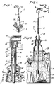
- Fig. 1 is a perspective view of one embodiment of the invention, in this instance a spigot apparently pouring "beer” into a beer bottle.
- Fig. 2 is a side elevation, partially in section, showing the inside of the base and the bottle.
- Fig. 3 is a vertical section showing the passages for, and flow of, the water and air.
- Fig 4 is a vertical section through the mixing chamber.
- Fig. 5 is a horizontal section, taken on line 5-5 of Fig. 3, showing the centering bushing which holds the various tubes used in the display device.
- Fig. 6 is a section taken on line 6-6 of Fig. 5.
- Fig. 7 is a section, taken on line 7-7 of Fig. 4, showing the mixing chamber.
- the display embodying the present invention creates an illusion which makes it appear that liquid is continuously flowing from an unattached spigot into a vessel which never fills up.
- the display is a unit or device including a base 3 having a receptacle 5 on it.
- a beer bottle is shown with a transparent outer tube 7 running from the mouth of the bottle, vertically to an unattached spigot 9.
- a bubbly air and water mix indicated at 12 in Fig. 3 is seen flowing down tube 7.
- the water can be colored to look like beer or some other beverage such as cola.
- the top 29 of bottle 5 is sealed around outer tube 7 so that the joint is substantially air and water tight. This prevents or reduces evaporation of the water.
- base 3 can carry cubes 21 of imitation ice.
- the ice and the bottle are illuminated by lamps 23 and 25.
- a water tube 17 is positioned concentrically inside tube 7 (Figs. 2 and 3). This tube serves to carry water 11 upward to the spigot end of tube 7.
- the water which collects in bottomless bottle 5 interconnected with base 3, is forced upwardly by a pump 15. The water flows downwardly to the bottle in the space between outer tube 7 and inner water tube 17.
- Water tube 17 may be colored the color that is desired for the liquid, so that the downwardly flowing water appears to be the color of the tube. Alternatively, dye can be added to the water.
- Tube 45 runs from the neck of bottle 5 upwardly between outer tube 7 and inner water tube 17 to the spigot area. Tube 45 is best hidden if it is located on the rearward side of the display.
- Outer tube 7 and air tube 45 are supported by a tube-centering bushing 33, positioned in the neck of the bottle.
- Bushing 33 includes centering pins for water tube 17, a base for outer tube 7, a supporting pin for air tube 45, and spacers 39 to center the bushing itself (Figs. 3 and 6).
- Air 10 from within the bottle, enters tube 45 through holes 47 in the tube, and is drawn upwardly by suction, for example by a Venturi-like action, to a mixing chamber 51, located at the top of tubes 7, 17, and 45, and just inside the outlet of spigot 9.
- the water and air are mixed in mixing chamber 51, producing a frothy mixture which they goes down to the bottle in the space between outer tube 7 and inner water tube 17.
- Mixing chamber 51 fits within the end of the spigot and the upper end of outer tube 7. It has an air-receiving well 53 with a base 55. Air from air tube 45 enters well 53 through air inlet opening 57. Air leaves the well through an air outlet opening 59, the latter being connected, via slot 61, to the space between tubes 7 and 17. Water, forced upwardly through inner water tube 17 by pump 15, passes through water return openings into outer tube 7. In so doing, it creates a Venturi-like effect or suction which pulls air upwardly through air tube 45, into air-receiving well 53, and out of air outlet 59 and slot 61. The air mixes with the water and creates the bubbly, frothy effect, and thus permits the water to be seen more readily as it flows down between outer tube 7 and inner tube 17. This water flow conceals inner tube 17 from view and so helps to create the illusion.
- this display is a closed, recirculatory system.
- the water which forms the stream from the spigot goes into base 3 and is pumped back upward to be reused.
- the air which comes down with the water goes into the bottle and is sucked up tube 45 for reuse.
- Bottle 5 has an inconspicuous corked opening 31 in the back of the neck, permitting initial filling and change of liquids.
- this display overcomes the problems of earlier displays in that evaporation is eliminated or greatly reduced, and persons cannot accidentally bump into the water stream and get themselves or their clothes wet.
Landscapes
- Business, Economics & Management (AREA)
- Accounting & Taxation (AREA)
- Marketing (AREA)
- Physics & Mathematics (AREA)
- General Physics & Mathematics (AREA)
- Engineering & Computer Science (AREA)
- Theoretical Computer Science (AREA)
- Toys (AREA)
- Nozzles (AREA)
Claims (14)
- Darstellung (1) zum Erzeugen der Illusion einer von einer nicht gebundenen Quelle strömenden Flüssigkeit; diese Darstellung umfaßt eine Behälteranordnung (3, 5), einen Leitungszapfen oder eine andere Vorrichtung, die eine nicht gebundene, in beabstandeter Beziehung zu der Behälteranordnung positionierte Quelle (9) vortäuscht, eine erste von der Behälteranordnung (3, 5) zu der vorgetäuschten Quelle verlaufende Röhre (17) und Mittel (15), um die Flüssigkeit (11) zu veranlassen, entlang der ersten Röhre von der Behälteranordnung in Richtung auf die vorgetäuschte Quelle zu strömen, dadurch gekennzeichnet, daß die erste Röhre (17) innerhalb einer zweiten, transparenten Außenröhre untergebracht ist, die auch von der Behälteranordnung (3, 5) zu der vorgetäuschten Quelle (9) verläuft, die erste und die zweite Röhre (17, 7) an oder nahegelegen ihren Enden, nahegelegen der vorgetäuschten Quelle miteinander verbunden sind, wodurch beim Gebrauch, wenn die Flüssigkeit (11) durch das genannte Mittel (15) veranlaßt wird, entlang der inneren, ersten Röhre (17) zu strömen, die Flüssigkeit auch veranlaßt wird, durch die äußere, zweite Röhre zwischen der ersten und der zweiten Röhre von der vorgetäuschten Quelle (9) in Richtung auf die Behälteranordnung (3, 5) zu strömen.
- Darstellung wie in Anspruch 1 beansprucht, die Mittel (45) umfaßt, um Luft in die Flüssigkeit zu speisen, wodurch die Flüssigkeit, die durch die äußere, zweite Röhre (7) zwischen der ersten und der zweiten Röhre strömt, beim Gebrauch eine sprudelnde Erscheinung haben wird.
- Darstellung wie in Anspruch 2 beansprucht, in der das genannte Lufteinspeisemittel (45) nutzbar ist, um Luft in die Flüssigkeit am Verbindungsort zwischen der ersten und der zweiten Röhre (17, 7) einzuspeisen.
- Darstellung wie in den Ansprüchen 2 oder 3 beansprucht, in der das Lufteinspeisemittel (45) eine dritte Luftröhre umfaßt, die innerhalb der äußeren, zweiten Röhre (7) zwischen der ersten und der zweiten Röhre angebracht ist und mit der äußeren, zweiten Röhre kommuniziert.
- Darstellung wie in Anspruch 4 beansprucht, in der die Luftröhre (45), an oder nahegelegen einem Ende (57), mit der äußeren, zweiten Röhre (7) am Verbindungsort zwischen der ersten und der zweiten Röhre (17, 7) kommuniziert.
- Darstellung wie in Anspruch 5 beansprucht, in der sich das gegenüberliegende Ende der Luftröhre (45) in die Behälteranordnung (3, 5) fortsetzt und Lufteinlaßöffnungen (47) umfaßt.
- Darstellung wie in einem der Ansprüche 2 bis 6 beansprucht, umfassend eine Mischkammer (51), durch welche die erste und die zweite Röhre (17, 7) miteinander verbundenen sind, und in die Luft von dem Lufteinspeisemittel (45) eingespeist wird.
- Darstellung wie in Anspruch 7 beansprucht, in welcher der Flüssigkeitsstrom innerhalb der Mischkammer (51) nutzbar ist, um Luft von dem Lufteinspeisemittel (45) in die Mischkammer zu ziehen.
- Darstellung wie in einem der vorangehenden Ansprüche beansprucht, in der die vorgetäuschte Quelle (9) oberhalb der Behälteranordnung (3, 5) angebracht ist und die erste und die zweite Röhre (17, 7) im wesentlichen vertikal und konzentrisch verlaufen.
- Darstellung wie in einem der vorangehenden Ansprüche beansprucht, in der die vorgetäuschte Quelle (9) durch die äußere, zweite Röhre (7) mit der Behälteranordnung verbunden und getragen ist.
- Darstellung wie in einem der vorangehenden Ansprüche beansprucht, in der die Behälteranordnung einen Sockel (3) umfaßt, der einen Behälter (5) trägt, der Sockel und der Behälter miteinander verbunden und imstande sind, die Flüssigkeit zu halten, und in der das genannte Mittel (15) nutzbar ist, um die in dem Sockel (3) enthaltene Flüssigkeit entlang der inneren, ersten Röhre (17) zu der vorgetäuschten Quelle (9) zu drücken.
- Darstellung wie in einem der vorangehenden Ansprüche beansprucht, in der das genannte Mittel (15) eine Pumpe enthält, die innerhalb der Behälteranordnung montiert und mit der inneren, ersten Röhre (17) verbunden ist.
- Darstellung wie in einem der vorangehenden Ansprüche beansprucht, in der die äußere, zweite Röhre (7) farblos und die innere, erste Röhre (17) farbig ist, wodurch auf die Flüssigkeit Farbe übertragen wird, wenn sie entlang der äußeren, zweiten Röhre zwischen der ersten und zweiten Röhre strömt.
- Darstellung wie in einem der vorangehenden Ansprüche beansprucht, wobei die Darstellung ein geschlossener Kreislauf ist, der einen Luft- und Flüssigkeitsverlust aus der Darstellung verhindert.
Applications Claiming Priority (2)
| Application Number | Priority Date | Filing Date | Title |
|---|---|---|---|
| US746736 | 1991-08-19 | ||
| US07/746,736 US5109620A (en) | 1991-08-19 | 1991-08-19 | Flowing liquid illusion |
Publications (2)
| Publication Number | Publication Date |
|---|---|
| EP0528677A1 EP0528677A1 (de) | 1993-02-24 |
| EP0528677B1 true EP0528677B1 (de) | 1996-03-27 |
Family
ID=25002119
Family Applications (1)
| Application Number | Title | Priority Date | Filing Date |
|---|---|---|---|
| EP92307528A Expired - Lifetime EP0528677B1 (de) | 1991-08-19 | 1992-08-18 | Illusion einer strömenden Flüssigkeit |
Country Status (3)
| Country | Link |
|---|---|
| US (1) | US5109620A (de) |
| EP (1) | EP0528677B1 (de) |
| DE (1) | DE69209403T2 (de) |
Families Citing this family (10)
| Publication number | Priority date | Publication date | Assignee | Title |
|---|---|---|---|---|
| CN1047859C (zh) * | 1993-10-07 | 1999-12-29 | 3D展览有限公司 | 一种仿真显示组件 |
| US6053422A (en) * | 1997-07-12 | 2000-04-25 | Polzin, Jr.; Joseph J. | Fountain, kit, bracket and method of assembly |
| BR9804233A (pt) * | 1998-10-06 | 2000-05-02 | Francisco Jose Duarte Vieira | Display dinâmico-analógico para perfeita simulação de bebidas carbonatadas. |
| US6533430B2 (en) * | 2000-12-01 | 2003-03-18 | Gary A. Baranyai | Model train accessory incorporating lighted tube for visual effect |
| US6530530B1 (en) | 2002-05-20 | 2003-03-11 | Crown Technology, Inc. | Decorative fountain |
| US20040094236A1 (en) * | 2002-11-14 | 2004-05-20 | Crown Technology, Inc. | Methods for passivating stainless steel |
| US7347016B2 (en) * | 2003-01-30 | 2008-03-25 | Brian Dane | Apparatus providing at least a visual impression of fluid moving in a channel and method of attaching an apparatus providing said visual impression |
| USD561262S1 (en) * | 2006-11-22 | 2008-02-05 | Steven Schwenker | Solar powered water drip sign |
| US7975937B2 (en) * | 2008-04-04 | 2011-07-12 | Crystal Fountains Inc. | System for creating a water void display |
| WO2017210890A1 (zh) * | 2016-06-08 | 2017-12-14 | 尚艳燕 | 一种装饰水杯 |
Family Cites Families (11)
| Publication number | Priority date | Publication date | Assignee | Title |
|---|---|---|---|---|
| US1536188A (en) * | 1925-01-05 | 1925-05-05 | Earl A Brown | Continuously-flowing display device |
| US1712487A (en) * | 1926-09-30 | 1929-05-14 | Samuel J T Stout | Refreshment booth |
| US1990230A (en) * | 1933-06-12 | 1935-02-05 | Gray John De Witt | Animated display device |
| US2762202A (en) * | 1952-04-17 | 1956-09-11 | Ponsar Yves Marie | Siphons for the regulation of the upstream level of a liquid |
| US3371618A (en) * | 1966-02-18 | 1968-03-05 | Chambers John | Pump |
| DE2410570C2 (de) * | 1974-03-06 | 1982-04-29 | Basf Ag, 6700 Ludwigshafen | Vorrichtung zum Ansaugen und Verdichten von Gasen und deren Vermischung mit Flüssigkeit |
| DE2634494C2 (de) * | 1976-07-31 | 1983-04-14 | Bayer Ag, 5090 Leverkusen | Neue Injektoren zur Flüssigkeitsbegasung |
| GB2040531B (en) * | 1979-01-22 | 1983-02-09 | Brimacombe & Co Ltd John | Apparatus for simulating a gaseous beverage |
| GB2082362A (en) * | 1980-07-03 | 1982-03-03 | Mcmain Ian John Langford | Magic tap-advertising aid/ novelty/gimmick |
| FR2517097A1 (fr) * | 1981-11-24 | 1983-05-27 | Meyer Daniel | Dispositif d'ecoulement continu en circuit ferme d'un filet liquide issu d'une source sans alimentation apparente et remplissant un recipient |
| US4586280A (en) * | 1985-02-25 | 1986-05-06 | Brian Dane | Novelty advertising cap |
-
1991
- 1991-08-19 US US07/746,736 patent/US5109620A/en not_active Expired - Fee Related
-
1992
- 1992-08-18 EP EP92307528A patent/EP0528677B1/de not_active Expired - Lifetime
- 1992-08-18 DE DE69209403T patent/DE69209403T2/de not_active Expired - Fee Related
Also Published As
| Publication number | Publication date |
|---|---|
| DE69209403T2 (de) | 1996-11-07 |
| US5109620A (en) | 1992-05-05 |
| DE69209403D1 (de) | 1996-05-02 |
| EP0528677A1 (de) | 1993-02-24 |
Similar Documents
| Publication | Publication Date | Title |
|---|---|---|
| EP0528677B1 (de) | Illusion einer strömenden Flüssigkeit | |
| US4042151A (en) | Beverage mixing and dispensing machine | |
| JP2843013B2 (ja) | 容器装置 | |
| US5909826A (en) | Round drink dispenser | |
| CA1308397C (en) | Carbonating apparatus | |
| RU2005109919A (ru) | Устройство для розлива различных охлажденных напитков | |
| AU8708998A (en) | Method for preparing frothed milk or cafe creme | |
| KR100257101B1 (ko) | 애니메이션된 디스플레이어셈블리 | |
| DE3160516D1 (en) | Aerated drinks machine | |
| RU96108906A (ru) | Движущийся блок индикации | |
| KR19980703546A (ko) | 디스플레이 장치 | |
| US5988441A (en) | Fluid merchandiser for beverage dispenser | |
| US6550168B1 (en) | Promotional display with fluid movement | |
| US4921640A (en) | Venturi-tube bubble-forming container | |
| KR890009757A (ko) | 가변식 음료 분배기 | |
| US3120068A (en) | Activated display device | |
| US4747692A (en) | Beverage dispenser | |
| CN2179994Y (zh) | 一种液体连续流动的广告装置 | |
| AU6199998A (en) | Method and device for foaming beer in a spigot | |
| WO1990003636A1 (en) | Display signs | |
| CN222907855U (zh) | 多组份混合调酒器 | |
| JPH0423278Y2 (de) | ||
| EP1099662A1 (de) | Reklameeinheit für einen Getränkespender | |
| WO2022100874A1 (en) | Beverage dispensing apparatus displaying air bubbles in a liquid | |
| JPH08324694A (ja) | ビールディスペンサ |
Legal Events
| Date | Code | Title | Description |
|---|---|---|---|
| PUAI | Public reference made under article 153(3) epc to a published international application that has entered the european phase |
Free format text: ORIGINAL CODE: 0009012 |
|
| AK | Designated contracting states |
Kind code of ref document: A1 Designated state(s): DE ES FR GB IT SE |
|
| 17P | Request for examination filed |
Effective date: 19930802 |
|
| 17Q | First examination report despatched |
Effective date: 19950524 |
|
| GRAA | (expected) grant |
Free format text: ORIGINAL CODE: 0009210 |
|
| AK | Designated contracting states |
Kind code of ref document: B1 Designated state(s): DE ES FR GB IT SE |
|
| PG25 | Lapsed in a contracting state [announced via postgrant information from national office to epo] |
Ref country code: IT Free format text: LAPSE BECAUSE OF FAILURE TO SUBMIT A TRANSLATION OF THE DESCRIPTION OR TO PAY THE FEE WITHIN THE PRE;WARNING: LAPSES OF ITALIAN PATENTS WITH EFFECTIVE DATE BEFORE 2007 MAY HAVE OCCURRED AT ANY TIME BEFORE 2007. THE CORRECT EFFECTIVE DATE MAY BE DIFFERENT FROM THE ONE RECORDED.SCRIBED TIME-LIMIT Effective date: 19960327 Ref country code: FR Effective date: 19960327 Ref country code: ES Free format text: THE PATENT HAS BEEN ANNULLED BY A DECISION OF A NATIONAL AUTHORITY Effective date: 19960327 |
|
| REF | Corresponds to: |
Ref document number: 69209403 Country of ref document: DE Date of ref document: 19960502 |
|
| PG25 | Lapsed in a contracting state [announced via postgrant information from national office to epo] |
Ref country code: SE Effective date: 19960627 |
|
| EN | Fr: translation not filed | ||
| PLBE | No opposition filed within time limit |
Free format text: ORIGINAL CODE: 0009261 |
|
| STAA | Information on the status of an ep patent application or granted ep patent |
Free format text: STATUS: NO OPPOSITION FILED WITHIN TIME LIMIT |
|
| 26N | No opposition filed | ||
| PGFP | Annual fee paid to national office [announced via postgrant information from national office to epo] |
Ref country code: DE Payment date: 20000802 Year of fee payment: 9 |
|
| PGFP | Annual fee paid to national office [announced via postgrant information from national office to epo] |
Ref country code: GB Payment date: 20000803 Year of fee payment: 9 |
|
| PG25 | Lapsed in a contracting state [announced via postgrant information from national office to epo] |
Ref country code: GB Free format text: LAPSE BECAUSE OF NON-PAYMENT OF DUE FEES Effective date: 20010818 |
|
| GBPC | Gb: european patent ceased through non-payment of renewal fee |
Effective date: 20010818 |
|
| PG25 | Lapsed in a contracting state [announced via postgrant information from national office to epo] |
Ref country code: DE Free format text: LAPSE BECAUSE OF NON-PAYMENT OF DUE FEES Effective date: 20020501 |