EP0528568B1 - Cylindrical structure and apparatus including same - Google Patents
Cylindrical structure and apparatus including same Download PDFInfo
- Publication number
- EP0528568B1 EP0528568B1 EP92307002A EP92307002A EP0528568B1 EP 0528568 B1 EP0528568 B1 EP 0528568B1 EP 92307002 A EP92307002 A EP 92307002A EP 92307002 A EP92307002 A EP 92307002A EP 0528568 B1 EP0528568 B1 EP 0528568B1
- Authority
- EP
- European Patent Office
- Prior art keywords
- cylinder
- roller
- photosensitive
- photosensitive member
- image
- Prior art date
- Legal status (The legal status is an assumption and is not a legal conclusion. Google has not performed a legal analysis and makes no representation as to the accuracy of the status listed.)
- Expired - Lifetime
Links
- 238000000034 method Methods 0.000 claims description 17
- 238000012546 transfer Methods 0.000 claims description 10
- 238000004140 cleaning Methods 0.000 claims description 5
- 229910052782 aluminium Inorganic materials 0.000 claims description 4
- XAGFODPZIPBFFR-UHFFFAOYSA-N aluminium Chemical compound [Al] XAGFODPZIPBFFR-UHFFFAOYSA-N 0.000 claims description 4
- 239000011248 coating agent Substances 0.000 claims description 2
- 238000000576 coating method Methods 0.000 claims description 2
- 239000004411 aluminium Substances 0.000 claims 1
- 238000012360 testing method Methods 0.000 description 13
- 239000000853 adhesive Substances 0.000 description 12
- 230000001070 adhesive effect Effects 0.000 description 12
- 239000010410 layer Substances 0.000 description 12
- 230000035515 penetration Effects 0.000 description 12
- 238000005452 bending Methods 0.000 description 10
- 238000005520 cutting process Methods 0.000 description 9
- KFZMGEQAYNKOFK-UHFFFAOYSA-N Isopropanol Chemical compound CC(C)O KFZMGEQAYNKOFK-UHFFFAOYSA-N 0.000 description 6
- 230000002093 peripheral effect Effects 0.000 description 6
- AHVPOAOWHRMOBY-UHFFFAOYSA-N 2-(diethylamino)-1-[6,7-dimethoxy-1-[1-(6-methoxynaphthalen-2-yl)ethyl]-3,4-dihydro-1h-isoquinolin-2-yl]ethanone Chemical compound C1=C(OC)C=CC2=CC(C(C)C3C4=CC(OC)=C(OC)C=C4CCN3C(=O)CN(CC)CC)=CC=C21 AHVPOAOWHRMOBY-UHFFFAOYSA-N 0.000 description 5
- 239000000463 material Substances 0.000 description 5
- 230000007547 defect Effects 0.000 description 4
- 239000011241 protective layer Substances 0.000 description 4
- 230000001154 acute effect Effects 0.000 description 3
- 230000015572 biosynthetic process Effects 0.000 description 3
- 230000000052 comparative effect Effects 0.000 description 3
- 238000007598 dipping method Methods 0.000 description 3
- 239000000126 substance Substances 0.000 description 3
- 229920005177 Duracon® POM Polymers 0.000 description 2
- 229930182556 Polyacetal Natural products 0.000 description 2
- 230000002411 adverse Effects 0.000 description 2
- VSCWAEJMTAWNJL-UHFFFAOYSA-K aluminium trichloride Chemical compound Cl[Al](Cl)Cl VSCWAEJMTAWNJL-UHFFFAOYSA-K 0.000 description 2
- 239000002585 base Substances 0.000 description 2
- 239000005018 casein Substances 0.000 description 2
- BECPQYXYKAMYBN-UHFFFAOYSA-N casein, tech. Chemical compound NCCCCC(C(O)=O)N=C(O)C(CC(O)=O)N=C(O)C(CCC(O)=N)N=C(O)C(CC(C)C)N=C(O)C(CCC(O)=O)N=C(O)C(CC(O)=O)N=C(O)C(CCC(O)=O)N=C(O)C(C(C)O)N=C(O)C(CCC(O)=N)N=C(O)C(CCC(O)=N)N=C(O)C(CCC(O)=N)N=C(O)C(CCC(O)=O)N=C(O)C(CCC(O)=O)N=C(O)C(COP(O)(O)=O)N=C(O)C(CCC(O)=N)N=C(O)C(N)CC1=CC=CC=C1 BECPQYXYKAMYBN-UHFFFAOYSA-N 0.000 description 2
- 235000021240 caseins Nutrition 0.000 description 2
- 238000011161 development Methods 0.000 description 2
- 238000010586 diagram Methods 0.000 description 2
- 238000001746 injection moulding Methods 0.000 description 2
- 238000005259 measurement Methods 0.000 description 2
- 229920006324 polyoxymethylene Polymers 0.000 description 2
- 238000007639 printing Methods 0.000 description 2
- 230000003252 repetitive effect Effects 0.000 description 2
- 229920005989 resin Polymers 0.000 description 2
- 239000011347 resin Substances 0.000 description 2
- 238000003860 storage Methods 0.000 description 2
- 239000002344 surface layer Substances 0.000 description 2
- 230000003746 surface roughness Effects 0.000 description 2
- KXGFMDJXCMQABM-UHFFFAOYSA-N 2-methoxy-6-methylphenol Chemical compound [CH]OC1=CC=CC([CH])=C1O KXGFMDJXCMQABM-UHFFFAOYSA-N 0.000 description 1
- 229910000838 Al alloy Inorganic materials 0.000 description 1
- RYGMFSIKBFXOCR-UHFFFAOYSA-N Copper Chemical compound [Cu] RYGMFSIKBFXOCR-UHFFFAOYSA-N 0.000 description 1
- 239000007864 aqueous solution Substances 0.000 description 1
- 239000006229 carbon black Substances 0.000 description 1
- MVPPADPHJFYWMZ-UHFFFAOYSA-N chlorobenzene Chemical compound ClC1=CC=CC=C1 MVPPADPHJFYWMZ-UHFFFAOYSA-N 0.000 description 1
- 229920006026 co-polymeric resin Polymers 0.000 description 1
- 239000011247 coating layer Substances 0.000 description 1
- 229910052802 copper Inorganic materials 0.000 description 1
- 239000010949 copper Substances 0.000 description 1
- 239000006185 dispersion Substances 0.000 description 1
- 238000001035 drying Methods 0.000 description 1
- 230000007613 environmental effect Effects 0.000 description 1
- -1 hydrazone compound Chemical class 0.000 description 1
- 150000002500 ions Chemical class 0.000 description 1
- 239000007788 liquid Substances 0.000 description 1
- 239000004973 liquid crystal related substance Substances 0.000 description 1
- 238000004519 manufacturing process Methods 0.000 description 1
- 229910052751 metal Inorganic materials 0.000 description 1
- 239000002184 metal Substances 0.000 description 1
- 239000000203 mixture Substances 0.000 description 1
- 239000003973 paint Substances 0.000 description 1
- 229920001568 phenolic resin Polymers 0.000 description 1
- 239000005011 phenolic resin Substances 0.000 description 1
- IEQIEDJGQAUEQZ-UHFFFAOYSA-N phthalocyanine Chemical compound N1C(N=C2C3=CC=CC=C3C(N=C3C4=CC=CC=C4C(=N4)N3)=N2)=C(C=CC=C2)C2=C1N=C1C2=CC=CC=C2C4=N1 IEQIEDJGQAUEQZ-UHFFFAOYSA-N 0.000 description 1
- 229920002492 poly(sulfone) Polymers 0.000 description 1
- 229920002037 poly(vinyl butyral) polymer Polymers 0.000 description 1
- 230000001105 regulatory effect Effects 0.000 description 1
- 238000005488 sandblasting Methods 0.000 description 1
- 238000010008 shearing Methods 0.000 description 1
- 239000007921 spray Substances 0.000 description 1
- 238000003756 stirring Methods 0.000 description 1
- 239000000758 substrate Substances 0.000 description 1
- XLYOFNOQVPJJNP-UHFFFAOYSA-N water Substances O XLYOFNOQVPJJNP-UHFFFAOYSA-N 0.000 description 1
Images

Classifications
-
- G—PHYSICS
- G03—PHOTOGRAPHY; CINEMATOGRAPHY; ANALOGOUS TECHNIQUES USING WAVES OTHER THAN OPTICAL WAVES; ELECTROGRAPHY; HOLOGRAPHY
- G03G—ELECTROGRAPHY; ELECTROPHOTOGRAPHY; MAGNETOGRAPHY
- G03G21/00—Arrangements not provided for by groups G03G13/00 - G03G19/00, e.g. cleaning, elimination of residual charge
- G03G21/16—Mechanical means for facilitating the maintenance of the apparatus, e.g. modular arrangements
- G03G21/18—Mechanical means for facilitating the maintenance of the apparatus, e.g. modular arrangements using a processing cartridge, whereby the process cartridge comprises at least two image processing means in a single unit
- G03G21/1803—Arrangements or disposition of the complete process cartridge or parts thereof
- G03G21/181—Manufacturing or assembling, recycling, reuse, transportation, packaging or storage
-
- B—PERFORMING OPERATIONS; TRANSPORTING
- B21—MECHANICAL METAL-WORKING WITHOUT ESSENTIALLY REMOVING MATERIAL; PUNCHING METAL
- B21D—WORKING OR PROCESSING OF SHEET METAL OR METAL TUBES, RODS OR PROFILES WITHOUT ESSENTIALLY REMOVING MATERIAL; PUNCHING METAL
- B21D39/00—Application of procedures in order to connect objects or parts, e.g. coating with sheet metal otherwise than by plating; Tube expanders
- B21D39/04—Application of procedures in order to connect objects or parts, e.g. coating with sheet metal otherwise than by plating; Tube expanders of tubes with tubes; of tubes with rods
-
- G—PHYSICS
- G03—PHOTOGRAPHY; CINEMATOGRAPHY; ANALOGOUS TECHNIQUES USING WAVES OTHER THAN OPTICAL WAVES; ELECTROGRAPHY; HOLOGRAPHY
- G03G—ELECTROGRAPHY; ELECTROPHOTOGRAPHY; MAGNETOGRAPHY
- G03G15/00—Apparatus for electrographic processes using a charge pattern
- G03G15/06—Apparatus for electrographic processes using a charge pattern for developing
- G03G15/08—Apparatus for electrographic processes using a charge pattern for developing using a solid developer, e.g. powder developer
- G03G15/0806—Apparatus for electrographic processes using a charge pattern for developing using a solid developer, e.g. powder developer on a donor element, e.g. belt, roller
- G03G15/0818—Apparatus for electrographic processes using a charge pattern for developing using a solid developer, e.g. powder developer on a donor element, e.g. belt, roller characterised by the structure of the donor member, e.g. surface properties
-
- G—PHYSICS
- G03—PHOTOGRAPHY; CINEMATOGRAPHY; ANALOGOUS TECHNIQUES USING WAVES OTHER THAN OPTICAL WAVES; ELECTROGRAPHY; HOLOGRAPHY
- G03G—ELECTROGRAPHY; ELECTROPHOTOGRAPHY; MAGNETOGRAPHY
- G03G15/00—Apparatus for electrographic processes using a charge pattern
- G03G15/06—Apparatus for electrographic processes using a charge pattern for developing
- G03G15/08—Apparatus for electrographic processes using a charge pattern for developing using a solid developer, e.g. powder developer
- G03G15/09—Apparatus for electrographic processes using a charge pattern for developing using a solid developer, e.g. powder developer using magnetic brush
- G03G15/0921—Details concerning the magnetic brush roller structure, e.g. magnet configuration
- G03G15/0928—Details concerning the magnetic brush roller structure, e.g. magnet configuration relating to the shell, e.g. structure, composition
-
- G—PHYSICS
- G03—PHOTOGRAPHY; CINEMATOGRAPHY; ANALOGOUS TECHNIQUES USING WAVES OTHER THAN OPTICAL WAVES; ELECTROGRAPHY; HOLOGRAPHY
- G03G—ELECTROGRAPHY; ELECTROPHOTOGRAPHY; MAGNETOGRAPHY
- G03G15/00—Apparatus for electrographic processes using a charge pattern
- G03G15/75—Details relating to xerographic drum, band or plate, e.g. replacing, testing
- G03G15/751—Details relating to xerographic drum, band or plate, e.g. replacing, testing relating to drum
-
- G—PHYSICS
- G03—PHOTOGRAPHY; CINEMATOGRAPHY; ANALOGOUS TECHNIQUES USING WAVES OTHER THAN OPTICAL WAVES; ELECTROGRAPHY; HOLOGRAPHY
- G03G—ELECTROGRAPHY; ELECTROPHOTOGRAPHY; MAGNETOGRAPHY
- G03G21/00—Arrangements not provided for by groups G03G13/00 - G03G19/00, e.g. cleaning, elimination of residual charge
- G03G21/16—Mechanical means for facilitating the maintenance of the apparatus, e.g. modular arrangements
- G03G21/18—Mechanical means for facilitating the maintenance of the apparatus, e.g. modular arrangements using a processing cartridge, whereby the process cartridge comprises at least two image processing means in a single unit
- G03G21/1839—Means for handling the process cartridge in the apparatus body
- G03G21/1842—Means for handling the process cartridge in the apparatus body for guiding and mounting the process cartridge, positioning, alignment, locks
-
- G—PHYSICS
- G03—PHOTOGRAPHY; CINEMATOGRAPHY; ANALOGOUS TECHNIQUES USING WAVES OTHER THAN OPTICAL WAVES; ELECTROGRAPHY; HOLOGRAPHY
- G03G—ELECTROGRAPHY; ELECTROPHOTOGRAPHY; MAGNETOGRAPHY
- G03G21/00—Arrangements not provided for by groups G03G13/00 - G03G19/00, e.g. cleaning, elimination of residual charge
- G03G21/16—Mechanical means for facilitating the maintenance of the apparatus, e.g. modular arrangements
- G03G21/18—Mechanical means for facilitating the maintenance of the apparatus, e.g. modular arrangements using a processing cartridge, whereby the process cartridge comprises at least two image processing means in a single unit
- G03G21/1839—Means for handling the process cartridge in the apparatus body
- G03G21/1857—Means for handling the process cartridge in the apparatus body for transmitting mechanical drive power to the process cartridge, drive mechanisms, gears, couplings, braking mechanisms
-
- G—PHYSICS
- G03—PHOTOGRAPHY; CINEMATOGRAPHY; ANALOGOUS TECHNIQUES USING WAVES OTHER THAN OPTICAL WAVES; ELECTROGRAPHY; HOLOGRAPHY
- G03G—ELECTROGRAPHY; ELECTROPHOTOGRAPHY; MAGNETOGRAPHY
- G03G2215/00—Apparatus for electrophotographic processes
- G03G2215/00362—Apparatus for electrophotographic processes relating to the copy medium handling
- G03G2215/00535—Stable handling of copy medium
- G03G2215/00679—Conveying means details, e.g. roller
-
- G—PHYSICS
- G03—PHOTOGRAPHY; CINEMATOGRAPHY; ANALOGOUS TECHNIQUES USING WAVES OTHER THAN OPTICAL WAVES; ELECTROGRAPHY; HOLOGRAPHY
- G03G—ELECTROGRAPHY; ELECTROPHOTOGRAPHY; MAGNETOGRAPHY
- G03G2215/00—Apparatus for electrophotographic processes
- G03G2215/08—Details of powder developing device not concerning the development directly
- G03G2215/0855—Materials and manufacturing of the developing device
- G03G2215/0858—Donor member
- G03G2215/0863—Manufacturing
-
- G—PHYSICS
- G03—PHOTOGRAPHY; CINEMATOGRAPHY; ANALOGOUS TECHNIQUES USING WAVES OTHER THAN OPTICAL WAVES; ELECTROGRAPHY; HOLOGRAPHY
- G03G—ELECTROGRAPHY; ELECTROPHOTOGRAPHY; MAGNETOGRAPHY
- G03G2221/00—Processes not provided for by group G03G2215/00, e.g. cleaning or residual charge elimination
- G03G2221/16—Mechanical means for facilitating the maintenance of the apparatus, e.g. modular arrangements and complete machine concepts
- G03G2221/18—Cartridge systems
- G03G2221/183—Process cartridge
Definitions
- the present invention relates to:
- a cylindrical electrophotographic photosensitive member (hereinafter sometimes called a "photosensitive drum”) has been formed by providing both ends of a cylinder having a peripheral surface coated with a photoconductive substance with a terminal engaging member, such as a drum flange or drum gear for rotating the photosensitive drum (hereinafter simply called a “flange” or “gear”) engaged with the ends by bonding with an adhesive or by force fitting under an external pressure.
- a terminal engaging member such as a drum flange or drum gear for rotating the photosensitive drum
- the engagement by bonding has been effected by applying an appropriate amount of adhesive onto a part of the gear or flange to be inserted into the cylinder and, after the fitting, causing the adhesive to be completely cured while keeping the fitted members in a place (environment) not affected by a change in temperature or humidity.
- an instant adhesive, and an adhesive primer together with an anaerobic adhesive, etc. have been generally used selectively in view of the usage, purpose, required strength, etc.
- the invention is more particularly concerned with a roller, as described in patent application FR-A-2630364, comprising an open-ended cylinder and a torque transmitting member, the torque transmitting member having a spigot which is engaged in the open end of the cylinder, the spigot having a recess, and an end portion of the cylinder wall being bent into the recess to fasten the cylinder to the torque transmitting member.
- the recess is provided by an annular groove around the spigot, and an annular portion of the cylinder is crimped into the annular groove. Whilst this may provide an effective way of presenting relative axial movement between the cylinder and the torque transmitting member, it would appear to provide little resistance to relative rotational movement between the cylinder and torque transmitting member.
- the invention therefore enables the torque transmitting member to be secured to the cylinder so as to provide strong resistance to relative rotational, as well as relative axial, movement.
- the bending and cutting of the end portion of the cylinder to provide the tabs can be easily performed by using a wedge- or claw-shaped thrusting member.
- the cylinder end is fastened in intimate contact with the recess, the engagement is not affected by external influence even under various environmental conditions (ranging from low temperature - low humidity to high temperature - high humidity) to be able to keep a stable fastening force, thus providing a torque strength identical to or even higher than those obtained by conventional bonding or forcive fitting.
- Figure 1 is a sectional view of a photosensitive drum according to the present invention.
- Figure 2 is a sectional illustration of a bending and cutting step
- Figure 3 is a corresponding top plan view.
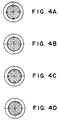
- Figure 4A - 4D are sectional views each showing a circular section example of a terminal engaging member engaged with a photosensitive drum according to the present invention.
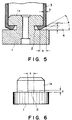
- Figure 5 is a sectional view for illustrating sizes involved in the bending and cutting step
- Figure 6 is a sectional view for illustrating the sizes of a recess of the terminal engaging member (gear or flange).
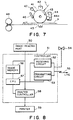
- Figure 7 is an illustration of an arrangement of an ordinary transfer-type electrophotographic apparatus using a photosensitive drum according to the present invention.
- Figure 8 is a block diagram of a facsimile apparatus including an electrophotographic apparatus equipped with a photosensitive drum according to the present invention as a printer.
- the cylinder may preferably have an end brim section having a thickness of 0.3 - 1.5 mm, particularly 0.5 - 1.5 mm.
- the cut length of the end brim during the bending and cutting step may preferably be at least 0.2 mm, particularly at least 0.25 mm. This point will be explained in further detail hereinafter.
- the cylindrical structure according to the present invention may effectively be used as various image bearing members inclusive of a photosensitive drum, first of all, and also as various roller members, such as a platen roller, a conveying roller, a developing sleeve, a fixing roller and a printing plate roller, to which a driving force is transmitted and which therefore require a strong engagement between a cylinder and a terminal engaging member constituting the same.
- various roller members such as a platen roller, a conveying roller, a developing sleeve, a fixing roller and a printing plate roller, to which a driving force is transmitted and which therefore require a strong engagement between a cylinder and a terminal engaging member constituting the same.
- the photosensitive drum i.e., a photosensitive member in a cylindrical form
- the photosensitive drum may take various forms so as to attain desired characteristics or depending on the kinds of electrophotographic processes applied thereto.
- Representative photosensitive members for electrophotography may include a photosensitive drum comprising a photoconductive layer formed on a cylindrical support and a photosensitive drum further including a surface protective layer thereon which have been widely used.
- the photosensitive drum comprising a cylindrical support and a photoconductive layer may be used for image formation by the most popular electrophotographic process including charging, imagewise exposure, development and further transfer as desired.
- such a protective layer may be provided for the purpose of, e.g., protecting the photoconductive layer, improving the mechanical strength of the photosensitive member, improving the dark decay characteristic, or providing a characteristic suited for a certain electrophotographic process.
- an electrostatic image formed on the electrophotographic photosensitive member is transferred to another image-bearing member for development, and the resultant toner image is transferred to a recording member.
- an electrostatic image is formed on an electrophotographic photosensitive member in the form of a screen having a large number of minute openings through a prescribed electrophotographic process, a corona charging treatment is applied to another image-bearing member by the medium of the electrostatic image to modulate the corona ion stream thereby forming an electrostatic image on the above-mentioned another image-bearing member, and the electrostatic image is developed with a toner and transferred to a recording member to form a final image.
- a toner image formed on an electrophotographic photosensitive member or another image-bearing member is not directly transferred to a recording member but is once transferred to still another image-bearing member, and the toner image is then transferred to a recording member to be fixed thereon.
- the recording member may ordinarily be a flexible material, such as paper or film. Accordingly, rather than transferring three color images to a recording member with precise positional alignment, a more accurately aligned color image can be formed if three color images are transferred onto an image-bearing member composed of a material substantially free from deformation and then transferred to a recording member at a time.
- the transfer of a toner image to a recording member by the medium of an image-bearing member is also effective for high-speed copying.
- an electric signal is applied to a multi-stylus electrode to form an electrostatic image on an image-bearing member corresponding to the electric signal, and the electrostatic image is developed to provide an image.
- the image-bearing members used in electrostatic image-forming process like those of (1) - (4) above do not require a photoconductive layer.
- cylindrical image-bearing members on which electrostatic images or toner images are formed may comprise various members which may generally have an insulating layer as the surface layer, including as a representative example an electrophotographic photosensitive member having a surface layer which may be a protective layer or a photoconductive layer.
- the cylindrical structure according to the present invention may for example be prepared in the following manner.
- a head (i.e., a part to be inserted into a cylinder) of a terminal engaging member is inserted into a cylinder of, e.g., aluminum, copper or stainless.
- Adjacent the head is disposed a recess toward the inside or axis of the terminal engaging member.
- the recess may have an appropriate shape (inclusive of width, length and depth).
- a generally claw- or wedge-shaped thrusting member having a tip forming an acute angle and having a width almost identical to the recess is abutted and pushed toward the inside of the recess in a certain amount of penetration, whereby the cylinder end brim is bent and sheared almost simultaneously in a shape conforming with the recess.
- the sheared part of the bent and cut end brim is intimately attached to and fitted with the recess contour, and the bent and cut part (particularly the inner surface thereof) of the end brim is intimately attached to the side and bottom of the recess, whereby a reliable fastening is secured.
- FIG. 1 is a sectional view of a photosensitive drum according to the present invention.
- the photosensitive drum includes a gear or flange 1 as a terminal engaging member engaged with the ends of the photosensitive drum for rotatably supporting the photosensitive drum and provided with recesses 2, and a cylinder (cylindrical substrate) 3 of aluminum alloy surface-coated with a photoconductive layer 5 of a photoconductive substance.
- the cylinder 3 is fitted about the gear or flange 1 with a certain fitting allowance and engaged with the gear or flange 1 at the recesses 2.
- the gear or flange 1 may be regarded as comprising a head (part to be inserted into the cylinder) 1a, a base 1b with or without teeth at its periphery (depending on whether it is a gear or flange) and recesses 2 formed between the head 1a and the base 1b.
- Figures 2 and 3 are a sectional view and a corresponding top plan view, respectively, for illustrating the bending and cutting of a cylinder end brim.
- a thrusting member 4 is abutted to and pushed against an end brim of the drum cylinder 3 after the gear or flange 1 is fitted into the cylinder 3 so as to thrust the end brim into the recess 2 of the gear or flange 1 while bending and shearing the brim.
- the cylinder 3 is fitted about the outer periphery of the head 1a of the gear or flange 1.
- the fitting at this stage should preferably be not too loose as to allow relative movement between both members but free from deformation of the outer surface of the cylinder 3 brim. More specifically, a clearance of 0 - 10 ⁇ m is preferred between the gear or flange and the cylinder 3.
- a claw- or wedge-shaped thrusting member 4 having a tip of an acute angle is abutted against the outer periphery of the cylinder 3 at four parts around the head 1a of the gear or flange 1 as shown in Figure 3.
- each of the four thrusting members 4 is disposed at the same height as the lower end of the cylinder 3, and the tip thereof having a width identical to the width of the recess 2 is disposed in horizontal alignment with an associated one of the recesses 2 of the gear or flange 1 fitted into the cylinder 3 as shown in Figure 3 and is then linearly moved along its axis for abutting.
- each thrusting member 4 is caused to go forward with a certain penetration toward the axis of the gear or flange 1, whereby the end brim is bent from its very lower end along the surface shape of the thrusting member 4 and, on further penetration, the end brim is sheared at parts corresponding to the widths of the recesses 2.
- cut and bent parts of the end brim are intimately attached and fixed in the recesses 2, so that the gear or flange 1 and the cylinder 3 are securely fastened to each other.
- the end brim is completely sheared and the sheared surface thereof is intimately attached to the contour of the recesses 2.
- the bent and cut part of the end brim is intimately fastened to the recess 2 so that a high engaging force is exhibited without allowing relative movement or loosening between the cylinder 3 and the gear or flange 1 in the directions of the rotation and axis of the photosensitive drum.
- the recess 2 may be formed at an arbitrary plurality of parts, e.g., 2 parts, 3 parts, 4 parts, 8 parts or even more parts, preferably point-symmetrically with respect to the axis of the gear or flange 1 as shown in Figure 4 for example.
- the end peripheral section of the cylinder 3 subjected to the bending and cutting may desirably be exposed, i.e., free of coating of a photosensitive substance, for a length of at least 1.0 mm, preferably at least 5.0 mm, from the very end in the longitudinal direction of the cylinder 3.
- the coating-free end section length should not be excessively large since it can decrease the image forming area formed by the coated area.
- the thrusting member 4 is allowed to enter for a penetration a toward inside the cylinder from the position where it just contacts the outer periphery of the cylinder 3.
- the cylinder 3 has a thickness b and may ordinarily comprise a drawn pipe of an aluminum-based metal.
- an aluminum-based drawn pipe (“H63S" (trade name) available from Kobe Seiko K.K.) having a thickness b of 0.7 mm (outer diameter: 29.92 mm, inner diameter: 28.50 mm) and a length of 260.5 mm was used.
- a larger thickness b provides a larger fastening torque strength, but too large a thickness b requires a very large force for bending and cutting by the thrusting member 4, thus adversely affecting the size accuracy of the surrounding parts.
- a thickness b of 0.3 - 1.5 mm, particularly 0.6 - 1.0 mm is preferred for sizes of a cylinder as described above.
- the thrusting member 4 may have a tip angle e which may be arbitrarily set in consideration of its shape, etc., but basically an acute angle, preferably in the range of 10 - 70 degrees, more preferably 20 - 40 degrees.
- a claw- or wedge-shaped thrusting member having smooth surfaces, a tip angle of 30 degrees and a width of 3 mm was used.
- the end brim of the cylinder 3 is cut in a length of f .
- a larger cut length f provides a larger fastening force.
- the cut length f may depend on the penetration a and may preferably be at least 0.2 mm, particularly at least 0.4 mm. However, the length f need not exceed 3 mm.
- Figure 6 illustrates sizes of the recess 2 formed in the gear or flange 1. More specifically, the recess 2 has a width (peripheral length in a direction transverse to the axis of the gear of flange 1) c , and a height (length in the direction of the axis of the gear or flange 1) d . These sizes of the recess 2 may be set to appropriate values depending on the outer diameter and the thickness of the drum cylinder 3. For the above-described sizes of the cylinder, for example, the width c may desirably be at least 1 mm, and the height d may desirable be at least 0.5 mm.
- the shape of the recess 2 is not limited to a rectangular one but may be circular, arc (partial circle), triangular, etc.
- the shape and size of the recess can be changed depending on the shape and outer diameter of the gear or flange 1, and the tip shape of the thrusting member 4 can be changed correspondingly.
- the cut and bent part of the cylinder end brim may preferably have a width which is in the range of 0.95 - 1 times the width of the recess 2, particularly identical to the width of the recess 2.
- Figure 7 shows an outline of an ordinary transfer-type electrophotographic apparatus including a photosensitive drum according to the present invention.
- the apparatus includes a photosensitive drum 41 as an image-bearing member which rotates about an axis 41a at a prescribed peripheral speed in the direction of the arrow.
- the peripheral surface of the photosensitive drum 41 is uniformly charged to a positive or negative prescribed potential by a charging means 42 and then exposed to image light L by an imagewise exposure means (not shown, such as slit exposure means or laser beam scanning exposure means) at an exposure position 43.
- an imagewise exposure means not shown, such as slit exposure means or laser beam scanning exposure means
- the electrostatic latent image is then developed with a toner by a developing means 44 including a developing sleeve 44a, and the resultant toner image is sequentially transferred by a transfer means 45 onto a transfer material or paper P which has been supplied between the photosensitive member 41 and the transfer means 45 in synchronism with the rotation of the photosensitive member 41 by a paper-supplying unit (not shown).
- a developing means 44 including a developing sleeve 44a the resultant toner image is sequentially transferred by a transfer means 45 onto a transfer material or paper P which has been supplied between the photosensitive member 41 and the transfer means 45 in synchronism with the rotation of the photosensitive member 41 by a paper-supplying unit (not shown).
- a paper-supplying unit not shown
- the transfer material P having received the toner image is separated from the photosensitive member surface and introduced to an image fixing means 48 for image fixation to be discharged as a copy product out of the apparatus.
- the surface of the photosensitive member 41 after the image transfer is subjected to removal of transfer-residual toner by a cleaning means 46 to be cleaned and used for repetitive image formation.
- a corona charging device is widely used in general as the uniform charging means 42 for the photosensitive member 41.
- a corona transfer means is also widely used in general as the transfer means 45.
- plural members including some of the above-mentioned photosensitive member 41, developing means 44, cleaning means 46, etc., can be integrally combined to form an apparatus unit so that the unit can be readily connected to or released from the apparatus body.
- the photosensitive member 41 and the cleaning means 46 can be integrated into a single unit so that it can be attached to or released from the apparatus body by a guide means such as a guide rail provided to the apparatus body.
- the apparatus unit can also be integrally accompanied with the charging means 42 and/or the developing means 44.
- the image light L is a reflected light or transmitted light from an original, or an image light formed by coding read data from an original and scanning a laser beam or driving a light-emitting diode array or a liquid crystal shutter array based on the coded data.
- the image light L may be replaced by exposure light image for printing received data.
- Figure 8 is a block diagram for illustrating such an embodiment.
- a controller 51 controls an image reader (or image reading unit) 50 and a printer 59.
- the entirety of the controller 51 is regulated by a CPU 57.
- Data read from the image reader 50 is transmitted through a transmitter circuit 53 to a remote terminal such as another facsimile machine.
- data received from a remote terminal is transmitted through a receiver circuit 52 to a printer 59.
- An image memory 56 stores prescribed image data.
- a printer controller 58 controls the printer 59.
- a telephone handset 54 is connected to the receiver circuit 52 and the transmitter circuit 53.
- an image received from a line (or circuit) 55 is demodulated by means of the receiver circuit 52, decoded by the CPU 57, and sequentially stored in the image memory 56.
- image data corresponding to at least one page is stored in the image memory 56
- image recording or output is effected with respect to the corresponding page.
- the CPU 57 reads image data corresponding to one page from the image memory 56, and transmits the decoded data corresponding to one page to the printer controller 58.
- the printer controller 58 controls the printer 59 so that image data recording corresponding to the page is effected.
- the CPU 57 receives another image data corresponding to the next page.
- receiving and recording of an image may be effected in the above-described manner by using an electrophotographic apparatus equipped with an image-bearing member according to the present invention as a printer.
- a photosensitive drum as shown in Figure 1 was prepared through a process as explained with reference to Figures 1 - 6 above.
- An aluminum-made drawn cylinder or tube (“H63S” (trade name) available from Kobe Seiko K.K.; inner diameter 28.50 mm and thickness of 0.7 mm respectively at the fitting ends; length: 260.5 mm) was coated by dipping with an ammoniacal aqueous solution of casein (casein 11.2 g, 28 %-ammonia water 1 g, water 222 ml), followed by drying to form a primer layer at a rate of 1.0 g/m 2 .
- casein casein 11.2 g, 28 %-ammonia water 1 g, water 222 ml
- a drum gear 1 having a section as shown in Figure 1 was formed from polyacetal copolymer resin ("Duracon M90-02" (trade name) available from Polyplastic K.K.) by injection molding (under the conditions of nozzle temp.: 200 °C, cylinder temp.: tip: 180 °C, medium: 170 °C, rear: 160 °C; mold temp.: cavity: 60 °C, core: 60 °C) to have a head (inserted part) outer diameter of 28.49 mm and four rectangular recesses (width: 3 mm, height: 1.5 mm, depth: 3 mm) at 4 parts adjacent to the head and disposed at right angles from the axis of the gear 1.
- Polyacetal copolymer resin "Duracon M90-02" (trade name) available from Polyplastic K.K.) by injection molding (under the conditions of nozzle temp.: 200 °C, cylinder temp.: tip: 180 °C, medium: 170 °C, rear: 160 °C; mold temp
- the above-prepared drum cylinder 3 was fitted so as to cover the head 1a of the gear 1 with its lower end brim, and four thrusting members 4 were caused to contact the outer surface of the lower end brim of the cylinder 3 as shown in Figure 3.
- Each thrusting member 4 had a tip having a width of 3 mm and an angle (e) of 30 degrees and formed of SKD 30.
- the thrusting members 4 were further pushed against the cylinder end brim at a penetration of 2.5 mm to bend and shear the end brim so as to conform to the shape of the recesses 2.
- the cut length of the cylinder end brim was 1.4 mm.
- the gear 1 was fastened to one end of the drum cylinder.
- Another gear was similarly fastened to the other end of the drum cylinder.
- the thus obtained photosensitive drum was loaded in a process cartridge for a laser beam printer ("LBP-SX" (trade name) available from Canon K.K.) and the process cartridge was left standing for 48 hours in an environment of high temperature - high humidity (32.5°C - 85 %RH). Then, the process cartridge was loaded in the laser beam printer and subjected to an image forming test of 10000 sheets. During the test, good images were obtained without occurrence of irregularities, such as pitch irregularities or fog, which might be attributable to the photosensitive drum. After the image forming test, the photosensitive drum was taken out of the cartridge to examine whether any defects, such as play, loosening and dislocation, occurred at the joint between the gear and the cylinder, no defects in these respects were observed at all. The photosensitive drum after the image forming test was fixed and subjected to measurement of a rupture torque at the joint by means of a commercially available torque gauge, whereby the rupture was caused at a torque of 160 kg-cm.
- LBP-SX trade name
- a photosensitive drum was prepared in the same manner as in Example 1 except that the thrusting member after the contact was further pushed to cause a penetration of 2.0 mm.
- the cut length at the sheared part of the cylinder end brim was 1.10 mm.
- the resultant photosensitive drum was evaluated in the same manner as in Example 1, whereby similar results were obtained.
- the rupture torque of the photosensitive drum at the joint after the image forming test was 145 kg-cm.
- a photosensitive drum was prepared in the same manner as in Example 1 except that the penetration of the thrusting member after the contact was changed to 1.5 mm.
- the cut length at the sheared part of the cylinder end brim was 0.85 mm.
- the resultant photosensitive drum was evaluated in the same manner as in Example 1, whereby similar results were obtained.
- the rupture torque of the photosensitive drum at the joint after the image forming test was 122 kg-cm.
- a photosensitive drum was prepared in the same manner as in Example 1 except that the penetration of the thrusting member after the contact was changed to 1.0 mm.
- the cut length at the sheared part of the cylinder end brim was 0.55 mm.
- the resultant photosensitive drum was evaluated in the same manner as in Example 1, whereby similar results were obtained.
- the rupture torque of the photosensitive drum at the joint after the image forming test was 70 kg-cm.
- a drum gear and a drum cylinder prepared in the same manner as in Example were bonded to each other with 0.08 g of an instant adhesive ("ARONALPHA 432FTW" (trade name) available from Toa Gosei Kagaku Kogyo K.K. and left standing for 48 hours in an environment of 32.5 °C and 85 %RH for complete curing.
- the resultant photosensitive drum was evaluated in the same manner as in Example 1, whereby the gear was dislocated after about 500 sheets of image formation. The part of the bonding failure was observed to be caused as an interfacial breakage at the boundary between the drum gear and the adhesive. The rupture torque at this time was 55 kg-cm.
- a drum cylinder and a drum gear prepared in the same manner as in Example 1 were fastened with each other in a similar manner as in Example 1 except that the thrusting member after contacting the periphery of the cylinder was further pushed to cause a penetration of only 0.5 mm whereby the gear was engaged with the cylinder only by staking, i.e. without causing cutting, of the cylinder.
- the thus prepared cylinder was evaluated in the same manner as in Example 1 whereby a play of about 0.5 mm occurred in the rotational direction at the time of 6000 sheets during the durability test. After the durability test, the joint between the photosensitive drum and the drum gear was observed, whereby the staked part of the cylinder was not sheared but a gap was found with the recess. The rupture disk at this time was 62 kg-cm.
- the resultant coating layer showed a surface roughness (Ra) of 3.0 ⁇ m.
- a flange having a head outer diameter of 14.38 mm made by injection molding of a polyacetal resin ("Duracon AW-01", made by Polyplastic K.K.) was fitted at a fit length of 3 mm.
- each thrusting member had a tip width of 3 mm and a tip angle of 30 degrees and was made of SKD 30.
- the thus-prepared developing sleeve was loaded in a cartridge for a laser beam printer ("LBP-SX", mfd. by Canon K.K.) and left standing for 48 hours in an environment of high temperature - high humidity (32.5°C - 85 %RH), and then the cartridge was loaded in the laser beam printer in the same environment and subjected to an image forming test of 10000 sheets. During the test, good images were obtained without occurrence of irregularities, such as pitch irregularities or fog. After the image forming test, the developing sleeve was taken out of the cartridge to examine whether any defects, such as play, loosening and dislocation, occurred at the joint between the gear and the cylinder, no defects in these respects were observed at all. The developing sleeve after the image forming test was fixed and subjected to measurement of a rupture torque at the joint by means of a commercially available torque gauge, whereby the rupture was caused at a torque of 60 kg-cm.
- LBP-SX laser beam printer
Landscapes
- Physics & Mathematics (AREA)
- General Physics & Mathematics (AREA)
- Engineering & Computer Science (AREA)
- Computer Vision & Pattern Recognition (AREA)
- Life Sciences & Earth Sciences (AREA)
- Manufacturing & Machinery (AREA)
- Sustainable Development (AREA)
- Mechanical Engineering (AREA)
- Discharging, Photosensitive Material Shape In Electrophotography (AREA)
Description
- The present invention relates to:
- a photosensitive roller or a developing roller for an electrophotographic image forming apparatus such as a copying machine, printer or facsimile apparatus;
- a process cartridge for such an apparatus and having at least one such roller; and
- such an apparatus having such a cartridge or at least one such roller.
- Hitherto, a cylindrical electrophotographic photosensitive member (hereinafter sometimes called a "photosensitive drum") has been formed by providing both ends of a cylinder having a peripheral surface coated with a photoconductive substance with a terminal engaging member, such as a drum flange or drum gear for rotating the photosensitive drum (hereinafter simply called a "flange" or "gear") engaged with the ends by bonding with an adhesive or by force fitting under an external pressure.
- The engagement by bonding has been effected by applying an appropriate amount of adhesive onto a part of the gear or flange to be inserted into the cylinder and, after the fitting, causing the adhesive to be completely cured while keeping the fitted members in a place (environment) not affected by a change in temperature or humidity. For the adhesive, an instant adhesive, and an adhesive primer together with an anaerobic adhesive, etc., have been generally used selectively in view of the usage, purpose, required strength, etc.
- However, several difficulties as mentioned below have been encountered with respect to conventional photosensitive drums prepared as described above.
- (1) In case where the bonding and curing are effected in a high temperature - high humidity environment (e.g., temperature: 32.5 °C, relative humidity: 85 %), moisture in the atmosphere adversely affects the bonding surface to result in a low torque strength.
- (2) Very long time is required until the complete curing of an adhesive depending on the kind of the adhesive used, so that a large space is required for the storage during the curing time and a facility for keeping the temperature and humidity of the storage is also required. Thus, several inconveniences are encountered also in respects of cost, management and productivity.
- (3) In order to obtain a high bonding strength, materials of gear and flanges are restricted.
- (4) In case where an electrical continuity with an apparatus body is taken by providing the gear or flange end with an electrode plate contacting the inner surface of the cylinder, flagging or flowing of the adhesive can occur before the complete curing to cause a conduction failure between the electrode plate and the inner surface of the cylinder.
- (5) In the case of force fitting, a sufficient strength of engagement has not been obtained between the gear or flange and the cylinder.
- The invention is more particularly concerned with a roller, as described in patent application FR-A-2630364, comprising an open-ended cylinder and a torque transmitting member, the torque transmitting member having a spigot which is engaged in the open end of the cylinder, the spigot having a recess, and an end portion of the cylinder wall being bent into the recess to fasten the cylinder to the torque transmitting member.
- In the roller described with reference to Figure 5 of FR-A-2630364, the recess is provided by an annular groove around the spigot, and an annular portion of the cylinder is crimped into the annular groove. Whilst this may provide an effective way of presenting relative axial movement between the cylinder and the torque transmitting member, it would appear to provide little resistance to relative rotational movement between the cylinder and torque transmitting member.
- In accordance with one aspect of the invention, there is provided a roller, wherein:
- the recess is one of a plurality of recesses which are circumferentially spaced around the spigot; and
- the end portion of the cylinder wall is cut to produce a plurality of tabs which are circumferentially spaced around the cylinder and each of which is bent into a respective one of the recesses so as to lock the cylinder and torque transmitting member against relative rotation.
- The invention therefore enables the torque transmitting member to be secured to the cylinder so as to provide strong resistance to relative rotational, as well as relative axial, movement.
- The bending and cutting of the end portion of the cylinder to provide the tabs can be easily performed by using a wedge- or claw-shaped thrusting member. As a result, the cylinder end is fastened in intimate contact with the recess, the engagement is not affected by external influence even under various environmental conditions (ranging from low temperature - low humidity to high temperature - high humidity) to be able to keep a stable fastening force, thus providing a torque strength identical to or even higher than those obtained by conventional bonding or forcive fitting.
- Other aspects of the invention are also provided, as set out in the opening paragraph of this specification. Preferred features of the invention are set out in the appended claims.
- Specific embodiments of the present invention will now be described by way of example with reference to the accompanying drawings, in which:-
- Figure 1 is a sectional view of a photosensitive drum according to the present invention.
- Figure 2 is a sectional illustration of a bending and cutting step, and Figure 3 is a corresponding top plan view.
- Figure 4A - 4D are sectional views each showing a circular section example of a terminal engaging member engaged with a photosensitive drum according to the present invention.
- Figure 5 is a sectional view for illustrating sizes involved in the bending and cutting step, and Figure 6 is a sectional view for illustrating the sizes of a recess of the terminal engaging member (gear or flange).
- Figure 7 is an illustration of an arrangement of an ordinary transfer-type electrophotographic apparatus using a photosensitive drum according to the present invention.
- Figure 8 is a block diagram of a facsimile apparatus including an electrophotographic apparatus equipped with a photosensitive drum according to the present invention as a printer.
- The cylinder may preferably have an end brim section having a thickness of 0.3 - 1.5 mm, particularly 0.5 - 1.5 mm. The cut length of the end brim during the bending and cutting step may preferably be at least 0.2 mm, particularly at least 0.25 mm. This point will be explained in further detail hereinafter.
- The cylindrical structure according to the present invention may effectively be used as various image bearing members inclusive of a photosensitive drum, first of all, and also as various roller members, such as a platen roller, a conveying roller, a developing sleeve, a fixing roller and a printing plate roller, to which a driving force is transmitted and which therefore require a strong engagement between a cylinder and a terminal engaging member constituting the same.
- The photosensitive drum, i.e., a photosensitive member in a cylindrical form, for electrophotography may take various forms so as to attain desired characteristics or depending on the kinds of electrophotographic processes applied thereto. Representative photosensitive members for electrophotography may include a photosensitive drum comprising a photoconductive layer formed on a cylindrical support and a photosensitive drum further including a surface protective layer thereon which have been widely used. The photosensitive drum comprising a cylindrical support and a photoconductive layer may be used for image formation by the most popular electrophotographic process including charging, imagewise exposure, development and further transfer as desired. As for the photosensitive drum provided with a protective layer, such a protective layer may be provided for the purpose of, e.g., protecting the photoconductive layer, improving the mechanical strength of the photosensitive member, improving the dark decay characteristic, or providing a characteristic suited for a certain electrophotographic process.
- Some other representative image forming processes, in which cylindrical image-bearing members may be used, are described below.
- (1) In order to improve the repetitive usability of an electrophotographic photosensitive member, an electrostatic image formed on the electrophotographic photosensitive member is transferred to another image-bearing member for development, and the resultant toner image is transferred to a recording member. (2) In another electrophotographic process involving forming an electrostatic image on another image-bearing member corresponding to an electrostatic image formed on an electrophotographic photosensitive member, an electrostatic image is formed on an electrophotographic photosensitive member in the form of a screen having a large number of minute openings through a prescribed electrophotographic process, a corona charging treatment is applied to another image-bearing member by the medium of the electrostatic image to modulate the corona ion stream thereby forming an electrostatic image on the above-mentioned another image-bearing member, and the electrostatic image is developed with a toner and transferred to a recording member to form a final image. (3) According to another electrophotographic process, a toner image formed on an electrophotographic photosensitive member or another image-bearing member is not directly transferred to a recording member but is once transferred to still another image-bearing member, and the toner image is then transferred to a recording member to be fixed thereon. This process is particularly effective for production of color images and high-speed copying. The recording member may ordinarily be a flexible material, such as paper or film. Accordingly, rather than transferring three color images to a recording member with precise positional alignment, a more accurately aligned color image can be formed if three color images are transferred onto an image-bearing member composed of a material substantially free from deformation and then transferred to a recording member at a time. Further, the transfer of a toner image to a recording member by the medium of an image-bearing member is also effective for high-speed copying. (4) In another process, an electric signal is applied to a multi-stylus electrode to form an electrostatic image on an image-bearing member corresponding to the electric signal, and the electrostatic image is developed to provide an image.
- The image-bearing members used in electrostatic image-forming process like those of (1) - (4) above do not require a photoconductive layer.
- Thus, cylindrical image-bearing members on which electrostatic images or toner images are formed may comprise various members which may generally have an insulating layer as the surface layer, including as a representative example an electrophotographic photosensitive member having a surface layer which may be a protective layer or a photoconductive layer.
- The cylindrical structure according to the present invention may for example be prepared in the following manner. A head (i.e., a part to be inserted into a cylinder) of a terminal engaging member is inserted into a cylinder of, e.g., aluminum, copper or stainless. Adjacent the head is disposed a recess toward the inside or axis of the terminal engaging member. The recess may have an appropriate shape (inclusive of width, length and depth). To an end brim part covering the recess of the cylinder, a generally claw- or wedge-shaped thrusting member having a tip forming an acute angle and having a width almost identical to the recess is abutted and pushed toward the inside of the recess in a certain amount of penetration, whereby the cylinder end brim is bent and sheared almost simultaneously in a shape conforming with the recess. The sheared part of the bent and cut end brim is intimately attached to and fitted with the recess contour, and the bent and cut part (particularly the inner surface thereof) of the end brim is intimately attached to the side and bottom of the recess, whereby a reliable fastening is secured.
- Hereinbelow, the present invention will be explained based on an embodiment wherein the cylindrical structure is constituted as a photosensitive drum with reference to drawings. Figure 1 is a sectional view of a photosensitive drum according to the present invention. Referring to Figure 1, the photosensitive drum includes a gear or flange 1 as a terminal engaging member engaged with the ends of the photosensitive drum for rotatably supporting the photosensitive drum and provided with
recesses 2, and a cylinder (cylindrical substrate) 3 of aluminum alloy surface-coated with aphotoconductive layer 5 of a photoconductive substance. Thecylinder 3 is fitted about the gear or flange 1 with a certain fitting allowance and engaged with the gear or flange 1 at therecesses 2. The gear or flange 1 may be regarded as comprising a head (part to be inserted into the cylinder) 1a, a base 1b with or without teeth at its periphery (depending on whether it is a gear or flange) andrecesses 2 formed between the head 1a and the base 1b. Figures 2 and 3 are a sectional view and a corresponding top plan view, respectively, for illustrating the bending and cutting of a cylinder end brim. For this purpose, a thrustingmember 4 is abutted to and pushed against an end brim of thedrum cylinder 3 after the gear or flange 1 is fitted into thecylinder 3 so as to thrust the end brim into therecess 2 of the gear or flange 1 while bending and shearing the brim. - The
cylinder 3 is fitted about the outer periphery of the head 1a of the gear or flange 1. The fitting at this stage should preferably be not too loose as to allow relative movement between both members but free from deformation of the outer surface of thecylinder 3 brim. More specifically, a clearance of 0 - 10 µm is preferred between the gear or flange and thecylinder 3. Then, after the gear or flange 1 and thecylinder 3 are fitted with each other, a claw- or wedge-shaped thrustingmember 4 having a tip of an acute angle is abutted against the outer periphery of thecylinder 3 at four parts around the head 1a of the gear or flange 1 as shown in Figure 3. At this time, as shown in Figure 2, each of the four thrustingmembers 4 is disposed at the same height as the lower end of thecylinder 3, and the tip thereof having a width identical to the width of therecess 2 is disposed in horizontal alignment with an associated one of therecesses 2 of the gear or flange 1 fitted into thecylinder 3 as shown in Figure 3 and is then linearly moved along its axis for abutting. Then, after the abutting, each thrustingmember 4 is caused to go forward with a certain penetration toward the axis of the gear or flange 1, whereby the end brim is bent from its very lower end along the surface shape of the thrustingmember 4 and, on further penetration, the end brim is sheared at parts corresponding to the widths of therecesses 2. As a result, cut and bent parts of the end brim are intimately attached and fixed in therecesses 2, so that the gear or flange 1 and thecylinder 3 are securely fastened to each other. - More specifically, at this time, the end brim is completely sheared and the sheared surface thereof is intimately attached to the contour of the
recesses 2. Thus, the bent and cut part of the end brim is intimately fastened to therecess 2 so that a high engaging force is exhibited without allowing relative movement or loosening between thecylinder 3 and the gear or flange 1 in the directions of the rotation and axis of the photosensitive drum. Therecess 2 may be formed at an arbitrary plurality of parts, e.g., 2 parts, 3 parts, 4 parts, 8 parts or even more parts, preferably point-symmetrically with respect to the axis of the gear or flange 1 as shown in Figure 4 for example. - The end peripheral section of the
cylinder 3 subjected to the bending and cutting may desirably be exposed, i.e., free of coating of a photosensitive substance, for a length of at least 1.0 mm, preferably at least 5.0 mm, from the very end in the longitudinal direction of thecylinder 3. The coating-free end section length should not be excessively large since it can decrease the image forming area formed by the coated area. - The sizes involved in the bending and cutting step will now be described with reference to Figure 5. Referring to Figure 5, the thrusting
member 4 is allowed to enter for a penetration a toward inside the cylinder from the position where it just contacts the outer periphery of thecylinder 3. By adjusting the penetration a, it is possible to control the fastening force between the gear or flange 1 and thecylinder 3. Thecylinder 3 has a thickness b and may ordinarily comprise a drawn pipe of an aluminum-based metal. In specific examples described hereinafter, an aluminum-based drawn pipe ("H63S" (trade name) available from Kobe Seiko K.K.) having a thickness b of 0.7 mm (outer diameter: 29.92 mm, inner diameter: 28.50 mm) and a length of 260.5 mm was used. A larger thickness b provides a larger fastening torque strength, but too large a thickness b requires a very large force for bending and cutting by the thrustingmember 4, thus adversely affecting the size accuracy of the surrounding parts. For this reason, a thickness b of 0.3 - 1.5 mm, particularly 0.6 - 1.0 mm, is preferred for sizes of a cylinder as described above. The thrustingmember 4 may have a tip angle e which may be arbitrarily set in consideration of its shape, etc., but basically an acute angle, preferably in the range of 10 - 70 degrees, more preferably 20 - 40 degrees. Incidentally, in the examples appearing hereinafter, a claw- or wedge-shaped thrusting member having smooth surfaces, a tip angle of 30 degrees and a width of 3 mm was used. - The end brim of the
cylinder 3 is cut in a length of f. A larger cut length f provides a larger fastening force. The cut length f may depend on the penetration a and may preferably be at least 0.2 mm, particularly at least 0.4 mm. However, the length f need not exceed 3 mm. - Figure 6 illustrates sizes of the
recess 2 formed in the gear or flange 1. More specifically, therecess 2 has a width (peripheral length in a direction transverse to the axis of the gear of flange 1) c, and a height (length in the direction of the axis of the gear or flange 1) d. These sizes of therecess 2 may be set to appropriate values depending on the outer diameter and the thickness of thedrum cylinder 3. For the above-described sizes of the cylinder, for example, the width c may desirably be at least 1 mm, and the height d may desirable be at least 0.5 mm. the shape of therecess 2 is not limited to a rectangular one but may be circular, arc (partial circle), triangular, etc. The shape and size of the recess can be changed depending on the shape and outer diameter of the gear or flange 1, and the tip shape of the thrustingmember 4 can be changed correspondingly. - The cut and bent part of the cylinder end brim may preferably have a width which is in the range of 0.95 - 1 times the width of the
recess 2, particularly identical to the width of therecess 2. - Figure 7 shows an outline of an ordinary transfer-type electrophotographic apparatus including a photosensitive drum according to the present invention.
- Referring to Figure 7, the apparatus includes a
photosensitive drum 41 as an image-bearing member which rotates about an axis 41a at a prescribed peripheral speed in the direction of the arrow. In the course of the rotation, the peripheral surface of thephotosensitive drum 41 is uniformly charged to a positive or negative prescribed potential by a charging means 42 and then exposed to image light L by an imagewise exposure means (not shown, such as slit exposure means or laser beam scanning exposure means) at anexposure position 43. As a result, an electrostatic latent image corresponding to the exposure light image is sequentially formed on the peripheral surface of thephotosensitive drum 41. - The electrostatic latent image is then developed with a toner by a developing
means 44 including a developing sleeve 44a, and the resultant toner image is sequentially transferred by a transfer means 45 onto a transfer material or paper P which has been supplied between thephotosensitive member 41 and the transfer means 45 in synchronism with the rotation of thephotosensitive member 41 by a paper-supplying unit (not shown). Herein, it is also possible to form the developing sleeve 44a as a cylindrical structure according to the present invention. - The transfer material P having received the toner image is separated from the photosensitive member surface and introduced to an image fixing means 48 for image fixation to be discharged as a copy product out of the apparatus.
- The surface of the
photosensitive member 41 after the image transfer is subjected to removal of transfer-residual toner by a cleaning means 46 to be cleaned and used for repetitive image formation. - A corona charging device is widely used in general as the uniform charging means 42 for the
photosensitive member 41. A corona transfer means is also widely used in general as the transfer means 45. - In the electrophotographic apparatus, plural members including some of the above-mentioned
photosensitive member 41, developingmeans 44, cleaning means 46, etc., can be integrally combined to form an apparatus unit so that the unit can be readily connected to or released from the apparatus body. For example, thephotosensitive member 41 and the cleaning means 46 can be integrated into a single unit so that it can be attached to or released from the apparatus body by a guide means such as a guide rail provided to the apparatus body. In this instance, the apparatus unit can also be integrally accompanied with the charging means 42 and/or the developingmeans 44. - In a case where the electrophotographic apparatus is used as a copying machine or a printer, the image light L is a reflected light or transmitted light from an original, or an image light formed by coding read data from an original and scanning a laser beam or driving a light-emitting diode array or a liquid crystal shutter array based on the coded data.
- In a case where the image forming apparatus is used as a printer for facsimile, the image light L may be replaced by exposure light image for printing received data. Figure 8 is a block diagram for illustrating such an embodiment.
- Referring to Figure 8, a
controller 51 controls an image reader (or image reading unit) 50 and aprinter 59. The entirety of thecontroller 51 is regulated by aCPU 57. Data read from theimage reader 50 is transmitted through atransmitter circuit 53 to a remote terminal such as another facsimile machine. On the other hand, data received from a remote terminal is transmitted through areceiver circuit 52 to aprinter 59. Animage memory 56 stores prescribed image data. Aprinter controller 58 controls theprinter 59. Atelephone handset 54 is connected to thereceiver circuit 52 and thetransmitter circuit 53. - More specifically, an image received from a line (or circuit) 55 (i.e., image data received from a remote terminal connected by the line) is demodulated by means of the
receiver circuit 52, decoded by theCPU 57, and sequentially stored in theimage memory 56. When image data corresponding to at least one page is stored in theimage memory 56, image recording or output is effected with respect to the corresponding page. TheCPU 57 reads image data corresponding to one page from theimage memory 56, and transmits the decoded data corresponding to one page to theprinter controller 58. When theprinter controller 58 receives the image data corresponding to one page from theCPU 57, theprinter controller 58 controls theprinter 59 so that image data recording corresponding to the page is effected. During the recording by theprinter 59, theCPU 57 receives another image data corresponding to the next page. - Thus, receiving and recording of an image may be effected in the above-described manner by using an electrophotographic apparatus equipped with an image-bearing member according to the present invention as a printer.
- A photosensitive drum as shown in Figure 1 was prepared through a process as explained with reference to Figures 1 - 6 above.
- An aluminum-made drawn cylinder or tube ("H63S" (trade name) available from Kobe Seiko K.K.; inner diameter 28.50 mm and thickness of 0.7 mm respectively at the fitting ends; length: 260.5 mm) was coated by dipping with an ammoniacal aqueous solution of casein (casein 11.2 g, 28 %-ammonia water 1 g, water 222 ml), followed by drying to form a primer layer at a rate of 1.0 g/m2.
- Then, 1 wt. part of aluminum chloride phthalocyanine, 1 wt. part of butyral resin ("Eslec BM-2" (trade name), available from Sekisui Kagaku K.K.) and 30 wt. parts of isopropyl alcohol were dispersed for 4 hours in a ball mill. The resultant dispersion was applied by dipping onto the above-prepared primer layer and dried to form a 0.3 µm-thick charge generation layer.
- Separately, 1 wt. part of a hydrazone compound, 1 wt. part of polysulfone resin ("P1700" (trade name) available from Union Carbide Co.) and 6 wt. parts of monochlorobenzene were mixed under stirring. The resultant liquid was applied onto the charge generation layer by dipping and dried to form a 12 µm-thick charge transport layer, thus providing a
coated drum cylinder 3 as shown in Figure 1 in a state before bending. - Separately, a drum gear 1 having a section as shown in Figure 1 was formed from polyacetal copolymer resin ("Duracon M90-02" (trade name) available from Polyplastic K.K.) by injection molding (under the conditions of nozzle temp.: 200 °C, cylinder temp.: tip: 180 °C, medium: 170 °C, rear: 160 °C; mold temp.: cavity: 60 °C, core: 60 °C) to have a head (inserted part) outer diameter of 28.49 mm and four rectangular recesses (width: 3 mm, height: 1.5 mm, depth: 3 mm) at 4 parts adjacent to the head and disposed at right angles from the axis of the gear 1.
- To the gear 1 thus obtained, the above-
prepared drum cylinder 3 was fitted so as to cover the head 1a of the gear 1 with its lower end brim, and four thrustingmembers 4 were caused to contact the outer surface of the lower end brim of thecylinder 3 as shown in Figure 3. Each thrustingmember 4 had a tip having a width of 3 mm and an angle (e) of 30 degrees and formed of SKD 30. After the contact, the thrustingmembers 4 were further pushed against the cylinder end brim at a penetration of 2.5 mm to bend and shear the end brim so as to conform to the shape of therecesses 2. The cut length of the cylinder end brim was 1.4 mm. Thus, the gear 1 was fastened to one end of the drum cylinder. Another gear was similarly fastened to the other end of the drum cylinder. - The thus obtained photosensitive drum was loaded in a process cartridge for a laser beam printer ("LBP-SX" (trade name) available from Canon K.K.) and the process cartridge was left standing for 48 hours in an environment of high temperature - high humidity (32.5°C - 85 %RH). Then, the process cartridge was loaded in the laser beam printer and subjected to an image forming test of 10000 sheets. During the test, good images were obtained without occurrence of irregularities, such as pitch irregularities or fog, which might be attributable to the photosensitive drum. After the image forming test, the photosensitive drum was taken out of the cartridge to examine whether any defects, such as play, loosening and dislocation, occurred at the joint between the gear and the cylinder, no defects in these respects were observed at all. The photosensitive drum after the image forming test was fixed and subjected to measurement of a rupture torque at the joint by means of a commercially available torque gauge, whereby the rupture was caused at a torque of 160 kg-cm.
- A photosensitive drum was prepared in the same manner as in Example 1 except that the thrusting member after the contact was further pushed to cause a penetration of 2.0 mm. The cut length at the sheared part of the cylinder end brim was 1.10 mm. The resultant photosensitive drum was evaluated in the same manner as in Example 1, whereby similar results were obtained. The rupture torque of the photosensitive drum at the joint after the image forming test was 145 kg-cm.
- A photosensitive drum was prepared in the same manner as in Example 1 except that the penetration of the thrusting member after the contact was changed to 1.5 mm. The cut length at the sheared part of the cylinder end brim was 0.85 mm. The resultant photosensitive drum was evaluated in the same manner as in Example 1, whereby similar results were obtained. The rupture torque of the photosensitive drum at the joint after the image forming test was 122 kg-cm.
- A photosensitive drum was prepared in the same manner as in Example 1 except that the penetration of the thrusting member after the contact was changed to 1.0 mm. The cut length at the sheared part of the cylinder end brim was 0.55 mm. The resultant photosensitive drum was evaluated in the same manner as in Example 1, whereby similar results were obtained. The rupture torque of the photosensitive drum at the joint after the image forming test was 70 kg-cm.
- A drum gear and a drum cylinder prepared in the same manner as in Example were bonded to each other with 0.08 g of an instant adhesive ("ARONALPHA 432FTW" (trade name) available from Toa Gosei Kagaku Kogyo K.K. and left standing for 48 hours in an environment of 32.5 °C and 85 %RH for complete curing. The resultant photosensitive drum was evaluated in the same manner as in Example 1, whereby the gear was dislocated after about 500 sheets of image formation. The part of the bonding failure was observed to be caused as an interfacial breakage at the boundary between the drum gear and the adhesive. The rupture torque at this time was 55 kg-cm.
- A drum cylinder and a drum gear prepared in the same manner as in Example 1 were fastened with each other in a similar manner as in Example 1 except that the thrusting member after contacting the periphery of the cylinder was further pushed to cause a penetration of only 0.5 mm whereby the gear was engaged with the cylinder only by staking, i.e. without causing cutting, of the cylinder.
- The thus prepared cylinder was evaluated in the same manner as in Example 1 whereby a play of about 0.5 mm occurred in the rotational direction at the time of 6000 sheets during the durability test. After the durability test, the joint between the photosensitive drum and the drum gear was observed, whereby the staked part of the cylinder was not sheared but a gap was found with the recess. The rupture disk at this time was 62 kg-cm.
- The surface of an Al pipe (outer dia. = 16 mm, thickness = 0.8 mm, length = 248 mm) was roughened by sand-blasting to a surface roughness (Ra) of 2.5 µm.
- Then, the Al pipe surface was spray-coated with a paint of the following composition:
Phenolic resin 20 wt. parts ("PLI-O-PHEN J-325, mfd. by Dai Nippon Ink K.K.) Carbon black 9 wt.parats (average diameter = 7 µm) Isopropyl alcohol 20 wt. parts - To both ends of the developing sleeve thus formed, a flange having a head outer diameter of 14.38 mm made by injection molding of a polyacetal resin ("Duracon AW-01", made by Polyplastic K.K.) was fitted at a fit length of 3 mm. The flange was provided with four rectangular recess (width = 3 mm, height = 1 mm, and depth = 3 mm) at 4 parts adjacent to the head and disposed at right angles from the axis of the flange.
- Then, to the end brim of the developing sleeve fitted about the head and recess of the flange, four thrusting members were abutted at the positions of the recesses and further pushed at a penetration of 1.5 mm against the end brim to bend and cut the brim at a cut length of 0.85 mm, whereby the flanges were fastened to the developing sleeve. Each thrusting member had a tip width of 3 mm and a tip angle of 30 degrees and was made of SKD 30.
- The thus-prepared developing sleeve was loaded in a cartridge for a laser beam printer ("LBP-SX", mfd. by Canon K.K.) and left standing for 48 hours in an environment of high temperature - high humidity (32.5°C - 85 %RH), and then the cartridge was loaded in the laser beam printer in the same environment and subjected to an image forming test of 10000 sheets. During the test, good images were obtained without occurrence of irregularities, such as pitch irregularities or fog. After the image forming test, the developing sleeve was taken out of the cartridge to examine whether any defects, such as play, loosening and dislocation, occurred at the joint between the gear and the cylinder, no defects in these respects were observed at all. The developing sleeve after the image forming test was fixed and subjected to measurement of a rupture torque at the joint by means of a commercially available torque gauge, whereby the rupture was caused at a torque of 60 kg-cm.
- The above-mentioned results of Examples and Comparative Examples are summarized in the following Table 1.

Claims (15)
- A photosensitive roller (41) or a developing roller (44a) for an electrophotographic image forming apparatus, the roller comprising an open-ended cylinder (3) and a torque transmitting member (1), the torque transmitting member having a spigot (la) which is engaged in the open end of the cylinder, the spigot having a recess (2), and an end portion of the cylinder wall being bent into the recess to fasten the cylinder to the torque transmitting member; wherein:the recess is one of a plurality of recesses (2) which are circumferentially spaced around the spigot; andthe end portion of the cylinder wall is cut to produce a plurality of tabs which are circumferentially spaced around the cylinder and each of which is bent into a respective one of the recesses so as to lock the cylinder and torque transmitting member against relative rotation.
- A roller according to claim 1, wherein the thickness of the cylinder wall adjacent the tabs is 0.3 - 1.5 mm.
- A roller according to claim 1 or 2, wherein the length of the cuts producing the tabs is at least 0.2 mm.
- A roller according to claim 3, wherein said length is at least 0.4 mm.
- A roller according to any preceding claim, wherein each tab has a width identical to the width of the respective recess.
- A roller according to any preceding claim, wherein the cylinder comprises an aluminium tube.
- A roller according to any preceding claim, wherein the torque transmitting member is formed as a gear (1b) for transmitting drive to or from the roller.
- A roller according to any preceding claim, wherein the other end of the cylinder is open-ended and the cylinder wall of the other end of the cylinder is cut to produce a plurality of further tabs which are circumferentially spaced around the cylinder and which are bent into respective recesses which are circumferentially spaced around a further spigot of a further member which is engaged in said other end of the cylinder.
- A roller according to any preceding claim, and being a photosensitive roller which is adapted to enable a developable latent image to be formed thereon.
- A roller according to claim 9, wherein the circumference of the cylinder of the photosensitive roller is coated with a photosensitive layer (5), and an end portion of the cylinder free from coating with the photosensitive layer (5) is cut to produce said plurality of tabs.
- A roller according to any of claims 1 to 8, and being a developing roller which is adapted to transfer toner to a photosensitive roller to develop a latent image thereon.
- A process cartridge for an electrophotographic image forming apparatus, comprising a photosensitive member, means for charging the photosensitive member, means for developing a latent image formed on the photosensitive member, and means for cleaning the photosensitive member, wherein the photosensitive member is provided by a roller as claimed in claim 9 or 10 and/or wherein the developing means includes a roller as claimed in claim 11.
- An electrophotographic image forming apparatus having a process cartridge according to claim 12.
- An electrophotographic image forming apparatus having a photosensitive member, means for charging the photosensitive member, means for developing a latent image formed on the photosensitive member, and means for cleaning the photosensitive member, wherein the photosensitive member is provided by a roller as claimed in claim 9 or 10 and/or wherein the developing means includes a roller as claimed in claim 11.
- An electrophotographic image forming apparatus according to claim 13 or 14, and in the form of a copying machine, printer or facsimile machine.
Applications Claiming Priority (2)
| Application Number | Priority Date | Filing Date | Title |
|---|---|---|---|
| JP19411791 | 1991-08-02 | ||
| JP194117/91 | 1991-08-02 |
Publications (2)
| Publication Number | Publication Date |
|---|---|
| EP0528568A1 EP0528568A1 (en) | 1993-02-24 |
| EP0528568B1 true EP0528568B1 (en) | 1997-05-28 |
Family
ID=16319204
Family Applications (1)
| Application Number | Title | Priority Date | Filing Date |
|---|---|---|---|
| EP92307002A Expired - Lifetime EP0528568B1 (en) | 1991-08-02 | 1992-07-31 | Cylindrical structure and apparatus including same |
Country Status (5)
| Country | Link |
|---|---|
| US (1) | US5771425A (en) |
| EP (1) | EP0528568B1 (en) |
| CN (1) | CN1032611C (en) |
| DE (1) | DE69219962T2 (en) |
| HK (1) | HK1000137A1 (en) |
Cited By (1)
| Publication number | Priority date | Publication date | Assignee | Title |
|---|---|---|---|---|
| US9612573B2 (en) | 2013-03-14 | 2017-04-04 | Clover Technologies Group, Llc | Method for removing gears |
Families Citing this family (23)
| Publication number | Priority date | Publication date | Assignee | Title |
|---|---|---|---|---|
| JP3334963B2 (en) * | 1993-02-01 | 2002-10-15 | キヤノン株式会社 | Coupling method for reconnecting a cylindrical member and an engagement member |
| JP3869913B2 (en) * | 1996-09-30 | 2007-01-17 | キヤノン株式会社 | Cylindrical member and process cartridge used in electrophotographic image forming apparatus |
| GB2319748B (en) * | 1996-11-30 | 2001-04-18 | Xerox Corp | Photoreceptor |
| KR100283816B1 (en) * | 1997-01-17 | 2001-03-02 | 이토가 미찌야 | Image carrier, method for manufacturing same, and image forming apparatus using same |
| US6075955A (en) * | 1998-01-23 | 2000-06-13 | Mitsubishi Chemical America, Inc. | Noise reducing device for photosensitive drum of an image forming apparatus |
| JP2000315037A (en) | 1999-04-28 | 2000-11-14 | Canon Inc | Electrophotographic photosensitive drum, process cartridge, and electrophotographic image forming apparatus |
| JP2001009546A (en) * | 1999-06-30 | 2001-01-16 | Kubota Tekkosho:Kk | Method for manufacturing hollow shaft having flange at one end |
| JP3723513B2 (en) * | 2001-04-25 | 2005-12-07 | 株式会社日立製作所 | Brake fluid pressure control unit for in-vehicle devices |
| JP3742354B2 (en) * | 2001-04-25 | 2006-02-01 | 株式会社日立製作所 | Brake fluid pressure control unit for in-vehicle devices |
| US6907205B2 (en) * | 2002-05-31 | 2005-06-14 | Mitsubishi Chemical America, Inc. | Coupling arrangement including drum and flange |
| US6788909B2 (en) | 2002-05-31 | 2004-09-07 | Mitsubishi Chemical America, Inc. | Coupling arrangement including drum, flange, and connector |
| JP4174380B2 (en) * | 2002-07-04 | 2008-10-29 | キヤノン株式会社 | Electrophotographic photosensitive drum and process cartridge |
| DE10251101B3 (en) * | 2002-11-04 | 2004-07-15 | Nexpress Solutions Llc | Fixing roller for electrophotographic printing machine with internal electrical heating element and end flanges fitted to cylindrical roller body |
| US7726000B2 (en) * | 2005-05-17 | 2010-06-01 | Dana Automotive Systems Group, Llc | Method of securing first and second splined members together |
| US7680435B2 (en) | 2006-01-26 | 2010-03-16 | Ricoh Company, Ltd. | Flange, flange processing device, and method of processing flange |
| US7747189B2 (en) | 2007-12-19 | 2010-06-29 | Wazana Brothers International | Process and apparatus for installing original drive gear on a laser printer toner cartridge drum |
| EP2657777A1 (en) * | 2009-03-20 | 2013-10-30 | Wazana Brothers International, Inc., d/b/a Micro Solutions Enterprises | Process and apparatus for installing original drive gear on a laser printer toner cartridge drum |
| JP5310522B2 (en) * | 2009-12-14 | 2013-10-09 | 富士ゼロックス株式会社 | End cover component and manufacturing method thereof, image carrier, image forming assembly, and image forming apparatus |
| CN102200707A (en) * | 2010-03-26 | 2011-09-28 | 富美科技有限公司 | Photosensitive drum |
| CN202106691U (en) * | 2011-06-23 | 2012-01-11 | 珠海天威飞马打印耗材有限公司 | Driving gear for printer |
| JP5929619B2 (en) * | 2012-08-10 | 2016-06-08 | 富士ゼロックス株式会社 | Tubular member |
| DE102018004731A1 (en) * | 2018-06-13 | 2019-12-19 | Interroll Holding Ag | conveyor roller |
| DE102018004720A1 (en) * | 2018-06-13 | 2019-12-19 | Interroll Holding Ag | conveyor roller |
Family Cites Families (15)
| Publication number | Priority date | Publication date | Assignee | Title |
|---|---|---|---|---|
| US1092464A (en) * | 1912-08-07 | 1914-04-07 | Watson Mfg Company | Metallic roller. |
| US2429293A (en) * | 1943-06-30 | 1947-10-21 | Parsons Engineering Corp | Method of making rollers |
| US4003334A (en) * | 1975-11-11 | 1977-01-18 | Speed-O-Print Business Machines Corporation | Developer roller for electrostatic copier |
| JPS5577746A (en) * | 1978-12-08 | 1980-06-11 | Kinoshita Kenkyusho:Kk | Electrophotographic photoreceptor |
| JPS55151673A (en) * | 1979-05-17 | 1980-11-26 | Canon Inc | Developing device |
| US4344218A (en) * | 1979-06-04 | 1982-08-17 | Continental Conveyor & Equipment Company, Inc. | Conveyor idler roll assembly and method of producing same |
| EP0036631B1 (en) * | 1980-03-26 | 1985-07-03 | Kabushiki Kaisha Toshiba | Electrostatic copying apparatus |
| JPS5886553A (en) * | 1981-11-19 | 1983-05-24 | Konishiroku Photo Ind Co Ltd | Drum-shaped image retaining body member |
| US4575221A (en) * | 1982-05-20 | 1986-03-11 | Canon Kabushiki Kaisha | Process kit and an image forming apparatus using the same |
| US4540268A (en) * | 1983-04-25 | 1985-09-10 | Canon Kabushiki Kaisha | Process kit and image forming apparatus using such kit |
| CN86210535U (en) * | 1985-12-27 | 1987-09-23 | 夏普公司 | Limit reaching monitoring device for waste toner |
| JPS62287258A (en) * | 1986-06-06 | 1987-12-14 | Ricoh Co Ltd | Electrophotographic photoreceptor |
| JPH01270082A (en) * | 1988-04-22 | 1989-10-27 | Harufumi Yamanaka | Manufacture of developing sleeve of copying machine |
| JPH089732Y2 (en) * | 1989-07-11 | 1996-03-21 | 三田工業株式会社 | Photoconductor drum |
| JPH03101751A (en) * | 1989-09-16 | 1991-04-26 | Canon Inc | Process cartridge |
-
1992
- 1992-07-31 EP EP92307002A patent/EP0528568B1/en not_active Expired - Lifetime
- 1992-07-31 DE DE69219962T patent/DE69219962T2/en not_active Expired - Lifetime
- 1992-08-01 CN CN92109002A patent/CN1032611C/en not_active Expired - Fee Related
-
1994
- 1994-07-18 US US08/276,484 patent/US5771425A/en not_active Expired - Lifetime
-
1997
- 1997-08-15 HK HK97101659A patent/HK1000137A1/en not_active IP Right Cessation
Cited By (1)
| Publication number | Priority date | Publication date | Assignee | Title |
|---|---|---|---|---|
| US9612573B2 (en) | 2013-03-14 | 2017-04-04 | Clover Technologies Group, Llc | Method for removing gears |
Also Published As
| Publication number | Publication date |
|---|---|
| CN1069347A (en) | 1993-02-24 |
| DE69219962T2 (en) | 1997-10-16 |
| EP0528568A1 (en) | 1993-02-24 |
| US5771425A (en) | 1998-06-23 |
| HK1000137A1 (en) | 1997-12-19 |
| CN1032611C (en) | 1996-08-21 |
| DE69219962D1 (en) | 1997-07-03 |
Similar Documents
| Publication | Publication Date | Title |
|---|---|---|
| US5771425A (en) | Mechanically fastened cylindrical engaging member for use in an image forming apparatus | |
| HK1000137B (en) | Cylindrical structure and apparatus including same | |
| US5907750A (en) | Cylindrical structure, process cartridge, and image forming apparatus | |
| US6336017B1 (en) | Mounting member for mounting a flange to an end of a cylindrical member of an electrophotographic photosensitive drum of a process cartridge, such a flange, such a drum, and such a process cartridge | |
| JP3869913B2 (en) | Cylindrical member and process cartridge used in electrophotographic image forming apparatus | |
| KR940006009A (en) | Photosensitive drums, process cartridges, image forming apparatuses and image forming systems | |
| US5815773A (en) | Composite photoreceptor flange | |
| AU702276B2 (en) | Developing device and electrophotographic image forming apparatus | |
| EP0589777B1 (en) | Image forming apparatus and process cartridge detachable to image forming apparatus main unit | |
| JPH09146411A (en) | Drum unit and ground plate used for drum unit | |
| JPH06324609A (en) | Cylindrical member | |
| JP2877570B2 (en) | Electrophotographic photoreceptor | |
| US5594531A (en) | Electrophotographic apparatus employing cylindrical member having space controlling member and press-fitted flange | |
| JP3126499B2 (en) | Cylindrical member, image holding member, developing sleeve, and device unit | |
| JPH06250576A (en) | Cylindrical member | |
| JPH05317992A (en) | Cylindrical member | |
| JPH07160146A (en) | Image forming device | |
| JP2000132000A (en) | Cylindrical member, developing sleeve and photosensitive drum | |
| JPH0720674A (en) | Rotating member, process cartridge, and image forming apparatus | |
| JPH1063141A (en) | Image forming device | |
| JP4013831B2 (en) | Electrophotographic photoreceptor | |
| JPH1048904A (en) | Image forming device | |
| JP2952123B2 (en) | Cylindrical member and electrophotographic apparatus using the same | |
| JP3661450B2 (en) | Image forming apparatus | |
| JP3661449B2 (en) | Image forming apparatus |
Legal Events
| Date | Code | Title | Description |
|---|---|---|---|
| PUAI | Public reference made under article 153(3) epc to a published international application that has entered the european phase |
Free format text: ORIGINAL CODE: 0009012 |
|
| AK | Designated contracting states |
Kind code of ref document: A1 Designated state(s): DE FR GB |
|
| 17P | Request for examination filed |
Effective date: 19930709 |
|
| 17Q | First examination report despatched |
Effective date: 19941209 |
|
| GRAG | Despatch of communication of intention to grant |
Free format text: ORIGINAL CODE: EPIDOS AGRA |
|
| GRAH | Despatch of communication of intention to grant a patent |
Free format text: ORIGINAL CODE: EPIDOS IGRA |
|
| GRAH | Despatch of communication of intention to grant a patent |
Free format text: ORIGINAL CODE: EPIDOS IGRA |
|
| GRAA | (expected) grant |
Free format text: ORIGINAL CODE: 0009210 |
|
| AK | Designated contracting states |
Kind code of ref document: B1 Designated state(s): DE FR GB |
|
| REF | Corresponds to: |
Ref document number: 69219962 Country of ref document: DE Date of ref document: 19970703 |
|
| ET | Fr: translation filed | ||
| PLBE | No opposition filed within time limit |
Free format text: ORIGINAL CODE: 0009261 |
|
| STAA | Information on the status of an ep patent application or granted ep patent |
Free format text: STATUS: NO OPPOSITION FILED WITHIN TIME LIMIT |
|
| 26N | No opposition filed | ||
| REG | Reference to a national code |
Ref country code: GB Ref legal event code: IF02 |
|
| PGFP | Annual fee paid to national office [announced via postgrant information from national office to epo] |
Ref country code: FR Payment date: 20100806 Year of fee payment: 19 Ref country code: DE Payment date: 20100731 Year of fee payment: 19 |
|
| PGFP | Annual fee paid to national office [announced via postgrant information from national office to epo] |
Ref country code: GB Payment date: 20100726 Year of fee payment: 19 |
|
| GBPC | Gb: european patent ceased through non-payment of renewal fee |
Effective date: 20110731 |
|
| REG | Reference to a national code |
Ref country code: FR Ref legal event code: ST Effective date: 20120330 |
|
| PG25 | Lapsed in a contracting state [announced via postgrant information from national office to epo] |
Ref country code: FR Free format text: LAPSE BECAUSE OF NON-PAYMENT OF DUE FEES Effective date: 20110801 Ref country code: DE Free format text: LAPSE BECAUSE OF NON-PAYMENT OF DUE FEES Effective date: 20120201 |
|
| REG | Reference to a national code |
Ref country code: DE Ref legal event code: R119 Ref document number: 69219962 Country of ref document: DE Effective date: 20120201 |
|
| PG25 | Lapsed in a contracting state [announced via postgrant information from national office to epo] |
Ref country code: GB Free format text: LAPSE BECAUSE OF NON-PAYMENT OF DUE FEES Effective date: 20110731 |