EP0527415B1 - Method and machine for packing ice cream cones - Google Patents
Method and machine for packing ice cream cones Download PDFInfo
- Publication number
- EP0527415B1 EP0527415B1 EP92113207A EP92113207A EP0527415B1 EP 0527415 B1 EP0527415 B1 EP 0527415B1 EP 92113207 A EP92113207 A EP 92113207A EP 92113207 A EP92113207 A EP 92113207A EP 0527415 B1 EP0527415 B1 EP 0527415B1
- Authority
- EP
- European Patent Office
- Prior art keywords
- cones
- rows
- grippers
- row
- rods
- Prior art date
- Legal status (The legal status is an assumption and is not a legal conclusion. Google has not performed a legal analysis and makes no representation as to the accuracy of the status listed.)
- Expired - Lifetime
Links
- 235000015243 ice cream Nutrition 0.000 title claims description 107
- 238000012856 packing Methods 0.000 title claims description 15
- 238000000034 method Methods 0.000 title claims description 9
- 230000033001 locomotion Effects 0.000 claims description 16
- 230000000694 effects Effects 0.000 claims description 5
- 238000006073 displacement reaction Methods 0.000 claims description 4
- 230000009471 action Effects 0.000 claims description 3
- 239000002131 composite material Substances 0.000 claims description 3
- 239000000853 adhesive Substances 0.000 claims description 2
- 230000001070 adhesive effect Effects 0.000 claims description 2
- 239000000463 material Substances 0.000 claims description 2
- 238000006386 neutralization reaction Methods 0.000 claims 1
- 239000000969 carrier Substances 0.000 description 2
- 230000010006 flight Effects 0.000 description 2
- 210000003739 neck Anatomy 0.000 description 2
- 230000004913 activation Effects 0.000 description 1
- 230000001174 ascending effect Effects 0.000 description 1
- 238000005266 casting Methods 0.000 description 1
- 238000006243 chemical reaction Methods 0.000 description 1
- 230000005484 gravity Effects 0.000 description 1
- 238000004519 manufacturing process Methods 0.000 description 1
- 230000007246 mechanism Effects 0.000 description 1
- 239000002184 metal Substances 0.000 description 1
- 238000004806 packaging method and process Methods 0.000 description 1
- 230000000717 retained effect Effects 0.000 description 1
- 238000005096 rolling process Methods 0.000 description 1
- 230000002459 sustained effect Effects 0.000 description 1
Images








Classifications
-
- B—PERFORMING OPERATIONS; TRANSPORTING
- B65—CONVEYING; PACKING; STORING; HANDLING THIN OR FILAMENTARY MATERIAL
- B65B—MACHINES, APPARATUS OR DEVICES FOR, OR METHODS OF, PACKAGING ARTICLES OR MATERIALS; UNPACKING
- B65B35/00—Supplying, feeding, arranging or orientating articles to be packaged
- B65B35/30—Arranging and feeding articles in groups
- B65B35/36—Arranging and feeding articles in groups by grippers
-
- B—PERFORMING OPERATIONS; TRANSPORTING
- B65—CONVEYING; PACKING; STORING; HANDLING THIN OR FILAMENTARY MATERIAL
- B65B—MACHINES, APPARATUS OR DEVICES FOR, OR METHODS OF, PACKAGING ARTICLES OR MATERIALS; UNPACKING
- B65B5/00—Packaging individual articles in containers or receptacles, e.g. bags, sacks, boxes, cartons, cans, jars
- B65B5/10—Filling containers or receptacles progressively or in stages by introducing successive articles, or layers of articles
- B65B5/105—Filling containers or receptacles progressively or in stages by introducing successive articles, or layers of articles by grippers
Definitions
- the invention relates to a method and machine for packing into boxes edible ice cream cones coming, from the production cycle, in the so-called baskets where they are arranged with their axes in a vertical condition, with their tips downwards and in a plurality of parallel rows.
- WO-A-8 203 209 there is contemplated a method and apparatus for packing ice ccream cones in which each cone is inserted inside a single sleeve-shaped carrier.
- the single carriers of the cones are fed singularly arranged vertically to a station where they are turned to an horizontal position. From this horizontal position the cones are pushed out of the carriers horizontally onto supporting means from which they are gripped by a gripping device which effects a rotation of 180° to transfer the cones horizontally to the packing box.
- the single carrying means of the gripping device can be turned 180° so that the cones may be located alternately in the box with the broadest end turning in opposite directions.
- FR-A-2 217 248 there is contemplated a method and apparatus for packing bottles in which the objects (bottles) are fed continuously along four staggered rows and then the outer rows of bottles are inclined horizontally with the bottle necks directed inwardly, while the inner rows are also inclined horizontally but with the necks directed outwardly.
- the cycle of packing into the boxes is concerned with a plurality of baskets at a time and, therefore, each cycle involves a plurality of boxes simultaneously, thus improving the output of the machine that operates according to the invention.
- each row of ice creams removed from the baskets comprises the ice creams which are required to form a layer in each of the boxes which are concerned simultaneously in each operative cycle of the machine.
- the assembly of the two baskets C positioned in the machine comprises four parallel longitudinal rows of ice creams, each comprising twelve ice cream cones arranged in a known manner, with their axes in a vertical condition and with their tips directed downwards.
- the boxes S can accommodate four layers of ice creams, each comprising four ice creams.
- Each of said longitudinal rows of ice creams in the two baskets C, comprising twelve ice creams, is used to constitute simultaneously one layer of ice creams in the assembly of three boxes S positioned in the machine.
- the device described above operates below the baskets C which have been positioned in the machine and lifts two adjacent rows of ice creams G by supporting them at the tip by means of said cup members 27.
- the unit 6 causes the carriage 5 to slide and positions the two rows of cup members 27, in a lowered position, axially in line with the two longitudinal rows of ice creams to be withdrawn from the baskets C which are retained in the machine by suitable means (not shown).
- the unit 10 lifts the two rows of cup members to cause the desired lifting of the ice creams and to position them for being gripped by the handling grippers described below. Thanks to the articulated motion permitted by the members 25-26, the cups 27 will match the ice creams to be lifted.
- the detents 24 are positioned at a short distance below the bars 28-128 which, with a suitable delay with respect to the lifting of the assembly 18-19, are moved outwards. If the ice creams have been normally lifted, the bars 28-128 do not interfere with the detents 24 of the lifted equipments.
- the mechanism for actuating the bars 28-128 is shown in the Figures 7 and 8.
- Said bars which have an inverted "L" configuration, are supported at the ends by supports 29-129 which are rotatably mounted on shafts 30-130 which are parallel to each other and to said bars and which, in turn, are sustained by the side frames of a structure 31 which is secured to the carriage 5.
- the shafts 30-130 are interconnected by levers 32-132 for self-centering motion.
- the shafts 30 of a bar are provided with respective angled levers 33-133 which are connected by tierods 34-134 to levers 35-135 which are connected perpendicularly to the ends of a shaft 36 which is parallel to said bars and is rotatably supported by the side frames of the structure 31.
- the base frame of the machine is of parallelepipedal configuration and comprises, above the conveyors 1-2, a horizontal frame 203 supporting a pair of horizontal guides 40 which are parallel both to each other and to said lower guides 4.
- Slidable on the guides 40 is a box-type carriage 41 which is connected laterally at 42 to one of the flights of a pair of parallel toothed belts 43-143 which are turned around toothed wheels 44-45 on one of which wheels said belts are interconnected by a drive shaft 46 which is actuated by an electronically-controlled, precision-type geared motor 47 provided with a brake.
- Said slides 48-148 carry further vertical guides 52-152 wherein there are slidably mounted carriages 53-153 which are connected to the flights of respective toothed belts 54-154 turned around toothed wheels 55-155 and 56-156 which are supported by the carriage 41, the lower ones being actuated by respective electronically-controlled geared motors 57-157 having an incorporated brake, protruding from the opposite sides of the carriage 41 ( Figure 3).
- the upper supports 58-158 carrying the guides 52-152 normally rest on the carriages 53-153 and follow due to gravity the descending movement thereof so that, should the descent of the slides 48-148 be obstructed by any obstacle, the actuators of said slides may operate unhindered.
- the carriages 53-153 are provided with projections which, via rolling means, co-operate with guides 59-159 secured to the side frames of the carriage 41.
- the frame 62 comprises a horizontal plate 63, secured to the slide 48, and an underlying plate 64 parallel to the plate 63 and connected thereto by means of crossmembers 65-66-67-68-69.
- a plate 70 is secured edgewise to the lower side of the plate 63.
- the crossmembers 65-66-67-68 are equally spaced apart and support a pair of rectilinear and parallel guides 71 whereon three groups of four sliding blocks 72a-73a-74a-75a, 72b-73b-74b-75b, 72c-73c-74c-75c slide with precision.
- the sliding blocks 72a-73a, 72b-73b, 72c-73c are integrally provided with a respective lug 76 directed upwards, whereas the other sliding blocks are integrally provided with a corresponding lug 77 directed downwards.
- the upper lugs 76 are traversed by a rod 78, whereas the lower lugs 77 are traversed by another rod 79, said rods 78-79 being parallel to the guides 71 and pre-arranged to freely traverse the crossmembers 66-67-68 and being connected to respective fluid-operated double-acting cylinder-and-piston units 80-81 arranged between the crossmembers 68 and 69 and secured to the last-mentioned crossmember.
- the rods 78 and 79 are provided with shoulders 84 and 85 which keep the lugs 76 and 77 of the sliding blocks 73a-73b-73c and 74a-74b-74c against stops 86 and 87 which are secured to the plates 70 and 64, respectively.
- the sliding blocks are brought together into a bundle to gather the ice creams to be packed into the boxes (see below), as shown in connection with the sliding blocks of the group "a" in the same Figure 9.
- the sliding blocks 72a-72b-72c will be brought into contact with the adjacent sliding blocks 73a-73b-73c and displace them as far as the lugs 76 of the latter engage the stops 88 which are fixed to the plate 70, while the sliding blocks 75a-75b-75c will be brought into contact with the adjacent sliding blocks 74a-74b-74c and bring the lugs 77 of the latter against stops 89 which are fixed to the plate 64.
- the displacement of the rods 78-79 is also controlled by the engagement of shoulders 90-91, fixed to said rods, against the crossmembers 67.
- sliding blocks mentioned above are pre-arranged to be articulated with their outer faces to the ends of respective composite U-shaped structures 92, by means of respective cylindrical articulated joints 93 lying in a common imaginary vertical plane and which are inclined in the same direction and by the same extent with respect to an imaginary horizontal plane.
- This inclination is the same or substantially the same as that of the generatrix of the conical ice cream G and the axis of said ice cream. In the example being discussed, said inclination is about on the order of ten degrees.
- the end portions of the frame 62 support two shafts 94 aligned to each other and parallel to the longitudinal axis of said frame, and said shafts rotatably mount respective L-shaped arms 95-195 (see also Figure 12) which are interconnected, at the sides remote from said rotational axes, by a suitably ribbed plate 96.
- the arms 95-195 have affixed thereto, co-axially to the shafts 94, toothed pulleys 97 which, via toothed belts 98, are connected to further toothed pulleys 99 keyed on a drive shaft 100 which is rotatably supported by the upper portion of the frame 62 and is actuated by one or more motors 101 of any suitable type.
- levers 102 Perpendicularly secured to the ends of the shaft 100 are levers 102 which, when the structure 95-195-96 is in the position shown in Figure 11 by solid lines, co-operate with respective decelerators 103 and limit stops 104 supported by the frame 62.
- the limit stops 105 and 106 secured to the end portions of the structure 95-195-96 cooperate with the respective decelerators 107 and limit stops 108 supported by the frame 62.
- FIGS 9-10-11-12 show that longitudinally secured to the plate 96 are U-shaped guides 109 aligned to each other, co-operating with a roller 200 mounted on the most overhanging portion of the structure 92 of each gripper which, thus, follows the pivotal movements of said structure 95-195-96.
- the spherical collars 117 of the rods of the various grippers P1 co-operate with a shaft 123 which is parallel to the shaft 94-94' and supported at the ends, so as to be rotatable about an eccentric axis 124, by the side frames of the pivotable structure 95-195-96.
- Flanged on an end portion structure is a sleeve 125 with a plate 126 supporting a small drive unit 127 for rotating said eccentric shaft.
- Suitable sensors (not shown) are provided to stop the rotation of the eccentric shaft 123-124 in the two positions corresponding to the opened and the closed positions of the grippers P1.
- the grippers associated with the vertical slide 148 are equal to the grippers P1 and are indicated at P2.
- the structures 192 supporting the grippers P2 are opposite mirror-images of the grippers 92, so that the pivotal movements of the rows of grippers P1 and P2 are symmetrically opposite with respect to the central plane 141 of the carriage 41 (see Figures 10 and 11).
- the grippers P1 and P2 are equally spaced apart as seen in Figure 3 and are in a lifted, vertical and opened condition as shown with solid lines in Figure 17.
- the trans-elevator assembly carrying the two rows of grippers P1-P2, moreover, is positioned so that the downwards extension of said central plane 141 is equally spaced from the two longitudinal adjacent rows of ice creams G to be withdrawn from the baskets C.
- Figure 16 shows with solid lines an ice cream G as disposed in the seat of a basket C, with a vertical axis.
- 93 indicates the skew pivotal axis of each structure 92-192 which carries one gripper P1 or P2 and which, for simplicity's sake, is supposed to be included in an imaginary vertical plane including the same axis of the ice cream and such as to intersect at A the edge of the top of said ice cream.
- the angle X formed by the axis 93 with a horizontal line B is equal or substantially equal to the angle X formed between the generatrix of the ice cream G and a vertical line D.
- Figure 23 shows a group of four grippers P1 after the upward rotation, as discussed above.
- the grippers P1 and P2 are gathered four by four, as shown in Figure 24, with activation of the cylinder-and-piston units 80-81 of Figure 9.
- the ice creams are thus gathered four by four and pre-arranged so that each group of four ice creams may be introduced into one of the three boxes S standing by at the filling station of the machine.
- the carriage 41 is moved in the direction of the boxes S to dispose on each of them a group of four ice creams supported by the gripper P1, the arrangement being such that the slide 48 effects a timed descending movement to bring the ice creams near said boxes.
- the slide 48 is returned to the upper initial position and when the grippers P1 have withdrawn from the boxes, the carriage 41 resumes its translational movement to dispose in a centered relation on the boxes S the four groups of ice creams which are supported by the grippers P2, as shown in Figure 19 with solid lines.
- the slide 148 is moved down to arrange the ice creams in the box when the grippers P2 will be opened, as shown with broken lines.
- a second layer is thus formed of ice creams G which will be disposed oppositely to the ice creams of the first layer and between them, as shown in Figure 1 with solid lines.
Landscapes
- Engineering & Computer Science (AREA)
- Mechanical Engineering (AREA)
- Confectionery (AREA)
Description
- The invention relates to a method and machine for packing into boxes edible ice cream cones coming, from the production cycle, in the so-called baskets where they are arranged with their axes in a vertical condition, with their tips downwards and in a plurality of parallel rows.
- According to prior art document WO-A-8 203 209 there is contemplated a method and apparatus for packing ice ccream cones in which each cone is inserted inside a single sleeve-shaped carrier. The single carriers of the cones are fed singularly arranged vertically to a station where they are turned to an horizontal position. From this horizontal position the cones are pushed out of the carriers horizontally onto supporting means from which they are gripped by a gripping device which effects a rotation of 180° to transfer the cones horizontally to the packing box. The single carrying means of the gripping device can be turned 180° so that the cones may be located alternately in the box with the broadest end turning in opposite directions.
- According to prior art document FR-A-2 217 248 there is contemplated a method and apparatus for packing bottles in which the objects (bottles) are fed continuously along four staggered rows and then the outer rows of bottles are inclined horizontally with the bottle necks directed inwardly, while the inner rows are also inclined horizontally but with the necks directed outwardly.
- The method of the present invention is characterized by the succession of the following operative steps:
- lifting and removal of two parallel rows of ice creams from their seats in the baskets, wherein each row comprises a number of ice creams which is required to form at least one layer in a box;
- 90° rotation of the two rows of ice creams, upwards and in opposite directions, so that, on completion of said rotation, the tips of the ice creams will be disposed at the outer side of the two rows. The rotation of the ice creams occurs on axes which are inclined with respect to the longitudinal axes of the two rows, whereby on completion of the rotation, the ice creams of each row will have horizontal and parallel generatrices which are perpendicular to the imaginary vertical plane which contains said inclined rotational axes;
- the ice creams of each of the two rows are moved towards each other and are pre-arranged according to a mutual spacing and plan view outline as required for packing in a box;
- transfer of the two rows of ice creams toward a box, whereafter one row of said ice creams is introduced into said box;
- once the first row of the ice creams has been packed into a box to form a first layer, the second row of ice creams is introduced into the box to form the second layer. The tips of the ice creams of the first layer are disposed at one side of the box, whereas the tips of the ice creams of the second layer are disposed at the opposite side of said box. The tips and the tops of the second layer ice creams are arranged between the tops and the tips, respectively, of the first layer ice creams;
- repetition of the steps listed above until the box has been filled completely, the ice creams of the odd layers (first, third, etc.) being superposed on each other and the ice creams of the even layers (second, fourth, etc.) being superposed on each other.
- Preferably, the cycle of packing into the boxes is concerned with a plurality of baskets at a time and, therefore, each cycle involves a plurality of boxes simultaneously, thus improving the output of the machine that operates according to the invention. In this instance, each row of ice creams removed from the baskets comprises the ice creams which are required to form a layer in each of the boxes which are concerned simultaneously in each operative cycle of the machine.
- Further characteristics of the invention and the advantages resulting therefrom will become apparent from the following description of a preferred embodiment thereof, shown merely as a non-limiting example in the Figures of the accompanying drawings, in which:
- Figure 1 is a plan view of the arrangement of the first and second layers of ice creams in a box;
- Figure 2 is a top plan view of the frame of the machine, of the conveyor for the baskets with the ice creams, and of the conveyor for the boxes wherein said ice creams shall be packed;
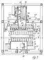
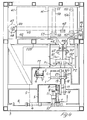
- Figures 3 and 4 are side elevational and front elevational views, respectively, of the machine;
- Figure 5 is a front elevational and partly sectional view of the trans-elevator unit carrying the two rows of grippers for handling the ice creams;
- Figures 6 and 7 are side elevational anf top plan views, respectively, of the two rows of elevators to lift the ice creams initially from the respective baskets;
- Figure 8 is a front elevational and partly sectional view of the group of elevators shown in Figures 6 and 7;
- Figure 9 is a side elevational and partly sectional view of the group of sliding blocks for transferring one of said two rows of grippers for handling the ice creams;
- Figures 10 and 11 are front elevational views showing, in the two operative positions, the two rows of grippers for handling the ice creams;
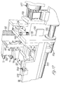
- Figure 12 is a perspective view of one of the ends of a pivotable structure which effects the reciprocating rotation of one of the two rows of grippers for handling the ice creams;
- Figure 13 is an enlarged elevational and partly sectional view, as from Figure 9, showing the skew connection between the body of each gripper for handling the ice creams to the respective transfer sliding block;
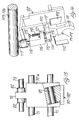
- Figures 14 and 15 are perspective views, from two different angular standpoints and in the raised or rotated upwards position, of one of the grippers for handling the ice creams;
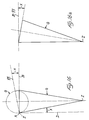
- Figures 16 and 16a are side elevational and top plan views, respectively, showing the movements imparted to the ice creams by the handling grippers;
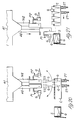
- Figures 17-18-19-20-21-22 are front elevational views of the groups for handling the two rows the ice creams, in as many significative steps of the cycle for packing four layers of ice creams into a box;
- Figures 23-24-25-26 are perspective views of four grippers for handling ice creams, in the successive steps of upwards rotation of the ice creams, mutual approaching of said ice creams, transfer and introduction of said ice creams into a packaging box.
- In Figures 2-3-4, the
numerals 1 and 2 indicate the horizontal, parallel, side-by-side conveyors whereby the conventional type baskets C containing ice creams G, and the boxes S for packing said ice creams are introduced into and removed from the machine being discussed. The conveyor 2 introduces the boxes S into the machine with their open sides upwards, in a single file, equally spaced apart as pre-established, in a suitable number (for example, in the number of three), and stops them in a pre-established position. Theconveyor 1 introduces the baskets C into the machine in single file, in a suitable number (for example, in the number of two) and stops them in a pre-established position which is centered with respect to the boxes S. In this instance, the assembly of the two baskets C positioned in the machine comprises four parallel longitudinal rows of ice creams, each comprising twelve ice cream cones arranged in a known manner, with their axes in a vertical condition and with their tips directed downwards. The boxes S can accommodate four layers of ice creams, each comprising four ice creams. Each of said longitudinal rows of ice creams in the two baskets C, comprising twelve ice creams, is used to constitute simultaneously one layer of ice creams in the assembly of three boxes S positioned in the machine. - The means for correctly positioning and retaining the boxes S and baskets C in the machine as described above are not considered herein because they may be easily conceived and constructed by those skilled in the art.
- It will be noted in Figures 2-3-4-6-7-8 that, under the conveyors 1-2, orthogonally thereto, the
frame 3 of the machine carries horizontal,rectilinear guides 4 whereon acarriage 5 slides by the action of a fluid-operated, double-acting cylinder andpiston unit 6. It is to be understood that thecarriage 5 may have a different shape other than the box like configuration shown herein. Secured on the front side of thecarriage 5 arevertical guides 7 whereon aslide 8 can slide; a projection of said slide extends through anopening 9 formed in the near wall of thecarriage 5, for connection to a rod of a fluid-operated cylinder andpiston unit 10, secured to the body of saidcarriage 5 by means of asupport 11. In Figure 7 it is also to be noted that, secured on theslide 8 connected to thecylinder 10, is aplate 12 carrying decelerators 13-14 and limit stops 15-16. - In Figures 4-7-8, more particularly, it is to be noted that secured on the
slide 8 is the intermediate portion of ahorizontal composite beam 17, parallel to the conveyors 1-2, on the sides of which there are securedvertical guides 18 in the number of twelve guides each side, spaced apart by the same distance existing between the ice creams of two longitudinal near rows in the baskets C. Slidably mounted in theguides 18, arevertical rods 19 having secured at its lower end abase member 20 which is kept in abutment against the lower end of said guides by means ofsprings 21 which are anchored to said base members and slides. Therods 19 are prevented from rotating due to the co-operation of a longitudinal groove thereof 22 with a key-like pin 23 secured to eachguide 18. This is necessary in order that thebase members 20 of the two rows of rods keep directed towards the inner space between said rows thanks to a detent 24 thereon to be discussed below. - Again in Figure 8, it is to be noted that mounted on the top end of each
rod 19 arebushes 25 which support, through the intermediary of asmall ball joint 26, a respective interiorly-conical cup member 27. - The device described above operates below the baskets C which have been positioned in the machine and lifts two adjacent rows of ice creams G by supporting them at the tip by means of said
cup members 27. Theunit 6 causes thecarriage 5 to slide and positions the two rows ofcup members 27, in a lowered position, axially in line with the two longitudinal rows of ice creams to be withdrawn from the baskets C which are retained in the machine by suitable means (not shown). Under command, theunit 10 lifts the two rows of cup members to cause the desired lifting of the ice creams and to position them for being gripped by the handling grippers described below. Thanks to the articulated motion permitted by the members 25-26, thecups 27 will match the ice creams to be lifted. It may occur that some of the ice creams stick in the seat of the basket due to the presence of ice. When thecups 27 reach the co-operating condition with the ice creams G, thedetents 24 are positioned at a short distance below the bars 28-128 which, with a suitable delay with respect to the lifting of the assembly 18-19, are moved outwards. If the ice creams have been normally lifted, the bars 28-128 do not interfere with thedetents 24 of the lifted equipments. However, if a few ice creams are stuck to a basket C and keep down thecup 27 with therod 19 andbase number 20, against the action of thesprings 21 which will be loaded progressively, said bars 28-128 superimpose thedetents 24 of said base members, which have remained in their lower position, so as to avoid that, should an ice cream separate abruptly from the basket, it may be thrown upwards by the release of the previously-loadedsprings 21. Before the lifting cups return to their lowered position to start a new cycle, the bars 28-128 are approached to each other so as to avoid interferring with the descent of thedetents 24 of the equipment normally lifted previously. - The mechanism for actuating the bars 28-128 is shown in the Figures 7 and 8. Said bars, which have an inverted "L" configuration, are supported at the ends by supports 29-129 which are rotatably mounted on shafts 30-130 which are parallel to each other and to said bars and which, in turn, are sustained by the side frames of a
structure 31 which is secured to thecarriage 5. The shafts 30-130 are interconnected by levers 32-132 for self-centering motion. Theshafts 30 of a bar are provided with respective angled levers 33-133 which are connected by tierods 34-134 to levers 35-135 which are connected perpendicularly to the ends of ashaft 36 which is parallel to said bars and is rotatably supported by the side frames of thestructure 31. Secured perpendicularly to the intermediate portion of theshaft 36 is alever 37 which through anend roller 38 follows the profile of a suitably shapedcam 39, arranged at one side of theslide 8. Therefore, the movement of the safety bars 28-128 is caused by the same ascending and descending movement of thecups 27 for lifting the ice creams. - From the Figures 3-4-5, it can be seen that the base frame of the machine is of parallelepipedal configuration and comprises, above the conveyors 1-2, a
horizontal frame 203 supporting a pair ofhorizontal guides 40 which are parallel both to each other and to saidlower guides 4. Slidable on theguides 40 is a box-type carriage 41 which is connected laterally at 42 to one of the flights of a pair of parallel toothed belts 43-143 which are turned around toothed wheels 44-45 on one of which wheels said belts are interconnected by adrive shaft 46 which is actuated by an electronically-controlled, precision-type gearedmotor 47 provided with a brake. More particularly, in Figures 5 and 3 it can be seen that two side-by-side slides carriage 41. Said slides are provided with respective pairs of vertical guides 49-149 which are slidable with precision in supports 50-150 and 51-151 which are secured to the opposite faces of an intermediatevertical wall 141 of thecarriage 41. Said slides 48-148 carry further vertical guides 52-152 wherein there are slidably mounted carriages 53-153 which are connected to the flights of respective toothed belts 54-154 turned around toothed wheels 55-155 and 56-156 which are supported by thecarriage 41, the lower ones being actuated by respective electronically-controlled geared motors 57-157 having an incorporated brake, protruding from the opposite sides of the carriage 41 (Figure 3). The upper supports 58-158 carrying the guides 52-152, normally rest on the carriages 53-153 and follow due to gravity the descending movement thereof so that, should the descent of the slides 48-148 be obstructed by any obstacle, the actuators of said slides may operate unhindered. - In order to grant the precision movement of the carriages 53-153, the latter are provided with projections which, via rolling means, co-operate with guides 59-159 secured to the side frames of the
carriage 41. - Since the weight of the slides 48-148 and parts associated therewith is of considerable amount, means are provided to partly compensate for said weight, so as to reduce the effects of inertia in the movement of said equipment and to increase their operative speed. Said compensation is effected by fluid-operated cylinder-and-
piston units 60, one for each slide 48-148 to which their rods are connected at 61-161, the body of said units being secured to thecarriage 41. - Secured to the lower end of each slide 48-148 is the intermediate portion of the respective horizontal frames 62-162 carrying the rows of grippers for handling the icecreams. Since said frames, grippers and respective drives, associated with each of the slides 48-148, are identical, the following description will be referred only to the means associated with the slide 48 (see Figure 9).
- The
frame 62 comprises ahorizontal plate 63, secured to theslide 48, and anunderlying plate 64 parallel to theplate 63 and connected thereto by means of crossmembers 65-66-67-68-69. Aplate 70 is secured edgewise to the lower side of theplate 63. The crossmembers 65-66-67-68 are equally spaced apart and support a pair of rectilinear andparallel guides 71 whereon three groups of four slidingblocks 72a-73a-74a-75a, 72b-73b-74b-75b, 72c-73c-74c-75c slide with precision. The slidingblocks 72a-73a, 72b-73b, 72c-73c are integrally provided with arespective lug 76 directed upwards, whereas the other sliding blocks are integrally provided with acorresponding lug 77 directed downwards. The upper lugs 76 are traversed by arod 78, whereas thelower lugs 77 are traversed by anotherrod 79, said rods 78-79 being parallel to theguides 71 and pre-arranged to freely traverse the crossmembers 66-67-68 and being connected to respective fluid-operated double-acting cylinder-and-piston units 80-81 arranged between thecrossmembers blocks 72a-72b-72c and thelower lugs 77 of the sliding blocks 75a-75b-75c are secured to the respective rods 78-79, for example, by pairs ofretainers rods shoulders lugs stops plates - During a step of the operative cycle of the machine, the sliding blocks are brought together into a bundle to gather the ice creams to be packed into the boxes (see below), as shown in connection with the sliding blocks of the group "a" in the same Figure 9. In this instance, as a result of the displacement of the rods 78-79, the sliding
blocks 72a-72b-72c will be brought into contact with the adjacent sliding blocks 73a-73b-73c and displace them as far as thelugs 76 of the latter engage thestops 88 which are fixed to theplate 70, while the sliding blocks 75a-75b-75c will be brought into contact with the adjacent sliding blocks 74a-74b-74c and bring thelugs 77 of the latter against stops 89 which are fixed to theplate 64. In this step, the displacement of the rods 78-79 is also controlled by the engagement of shoulders 90-91, fixed to said rods, against thecrossmembers 67. - With reference to Figures 3-4-5-9-10-11-12-13-14-15, it will be noted that the sliding blocks mentioned above are pre-arranged to be articulated with their outer faces to the ends of respective composite
U-shaped structures 92, by means of respective cylindrical articulatedjoints 93 lying in a common imaginary vertical plane and which are inclined in the same direction and by the same extent with respect to an imaginary horizontal plane. This inclination is the same or substantially the same as that of the generatrix of the conical ice cream G and the axis of said ice cream. In the example being discussed, said inclination is about on the order of ten degrees. - The end portions of the
frame 62 support twoshafts 94 aligned to each other and parallel to the longitudinal axis of said frame, and said shafts rotatably mount respective L-shaped arms 95-195 (see also Figure 12) which are interconnected, at the sides remote from said rotational axes, by a suitablyribbed plate 96. The arms 95-195 have affixed thereto, co-axially to theshafts 94,toothed pulleys 97 which, viatoothed belts 98, are connected to furthertoothed pulleys 99 keyed on adrive shaft 100 which is rotatably supported by the upper portion of theframe 62 and is actuated by one ormore motors 101 of any suitable type. Perpendicularly secured to the ends of theshaft 100 arelevers 102 which, when the structure 95-195-96 is in the position shown in Figure 11 by solid lines, co-operate withrespective decelerators 103 and limit stops 104 supported by theframe 62. When the structure 95-195-96 is in the position shown in Figures 10 and 11 by broken lines, and has rotated through 90° upwards, on thehorizontal axis 94, the limit stops 105 and 106 secured to the end portions of the structure 95-195-96 cooperate with the respective decelerators 107 and limit stops 108 supported by theframe 62. - Figures 9-10-11-12 show that longitudinally secured to the
plate 96 areU-shaped guides 109 aligned to each other, co-operating with aroller 200 mounted on the most overhanging portion of thestructure 92 of each gripper which, thus, follows the pivotal movements of said structure 95-195-96. - The end portion of each
structure 92 mounts a gripper P1 which, as shown in Figures 10-14 and 15, comprises: - a
jaw 110 made of suitably-shaped metal strip and prearranged to operate about tangentially on a portion of the side surface of an ice cream G. This jaw is secured to thestructure 92; - a
jaw 111 obtained by a casting process, exteriorly coated with non-adhesive material and so shaped as to co-operate with a portion of the side surface section of an ice cream that is gripped by theother jaw 110. Thejaw 111 is secured to the end of alever 112 inter-fulcrumed at 113 to thestructure 92 and the other end of which is fork-shaped for pivotal connection by means of apin 114, to arod 115 which is axially slidable in asmall guide 116 secured to thestructure 92, the other end of said rod protruding from said guide and being provided with aspherical collar 117. Secured to thelever 112 and to theconnection member 118 on theguide 116 are the ends of aspring 119 which urges thejaw 111 in the closing direction. In the closed condition, thelever 112 co-operates with anadjustable stop 120 carried by anextension 121 of theguide 116, which is of clamp-like configuration; - a
small plate member 122 arranged perpendicularly above said jaws, at a suitable distance therefrom, secured to thestructure 92 and adapted to co-operate with the top of an ice cream G. - The
spherical collars 117 of the rods of the various grippers P1, co-operate with ashaft 123 which is parallel to the shaft 94-94' and supported at the ends, so as to be rotatable about aneccentric axis 124, by the side frames of the pivotable structure 95-195-96. Flanged on an end portion structure is asleeve 125 with aplate 126 supporting asmall drive unit 127 for rotating said eccentric shaft. Suitable sensors (not shown) are provided to stop the rotation of the eccentric shaft 123-124 in the two positions corresponding to the opened and the closed positions of the grippers P1. - The grippers associated with the
vertical slide 148 are equal to the grippers P1 and are indicated at P2. Thestructures 192 supporting the grippers P2 are opposite mirror-images of thegrippers 92, so that the pivotal movements of the rows of grippers P1 and P2 are symmetrically opposite with respect to thecentral plane 141 of the carriage 41 (see Figures 10 and 11). - At the beginning of each working cycle, the grippers P1 and P2 are equally spaced apart as seen in Figure 3 and are in a lifted, vertical and opened condition as shown with solid lines in Figure 17. The trans-elevator assembly carrying the two rows of grippers P1-P2, moreover, is positioned so that the downwards extension of said
central plane 141 is equally spaced from the two longitudinal adjacent rows of ice creams G to be withdrawn from the baskets C. - While the two rows of ice creams G are lifted from the respective rows of
cups 27, the slides 48-148 are lowered in time with them and the two rows of grippers P1-P2 are rotated through 90° and are disposed horizontally to pick up said ice creams when lifted. The grippers are then closed to clamp the ice creams by means of their opposite jaws 110-111 which, by reaction, cause said ice creams to undergo a small axial displacement upwards whereby their tops will abut against theplate 122. After the ice creams have been clamped, while thecups 27 are moved down and pre-arranged to repeat their working cycle on the other two rows of ice creams (see below), the slides 48-148 are lifted and the rows of grippers P1-P2 are timedly rotated outwards through 90°, so as to dispose vertically as shown with solid lines in Figure 17. As a result of this rotation, the ice creams clamped by the grippers P1 and P2 are moved to a horizontal-axis condition and are ready for packing into a box, as described with reference to Figure 1. - Figure 16 shows with solid lines an ice cream G as disposed in the seat of a basket C, with a vertical axis. In this same Figure, 93 indicates the skew pivotal axis of each structure 92-192 which carries one gripper P1 or P2 and which, for simplicity's sake, is supposed to be included in an imaginary vertical plane including the same axis of the ice cream and such as to intersect at A the edge of the top of said ice cream. As stated above, the angle X formed by the
axis 93 with a horizontal line B is equal or substantially equal to the angle X formed between the generatrix of the ice cream G and a vertical line D. If the ice cream G is rotated through 90° as from Figure 16, about theaxis 93, the projection of the tip Z of said ice cream will superpose the point A and the top of the ice cream will dispose as indicated with broken lines. If, after said rotation, the ice cream G is seen in top plan view, it appears as from Figure 16a and the generatrix which was perpendicular to theaxis 93 is now disposed horizontally and perpendicularly to the imaginary vertical plane including saidskew axis 93. - Figure 23 shows a group of four grippers P1 after the upward rotation, as discussed above.
- After the step which is shown in Figures 17 and 23, the grippers P1 and P2 are gathered four by four, as shown in Figure 24, with activation of the cylinder-and-piston units 80-81 of Figure 9. The ice creams are thus gathered four by four and pre-arranged so that each group of four ice creams may be introduced into one of the three boxes S standing by at the filling station of the machine.
- As shown in Figures 18 and 25, the
carriage 41 is moved in the direction of the boxes S to dispose on each of them a group of four ice creams supported by the gripper P1, the arrangement being such that theslide 48 effects a timed descending movement to bring the ice creams near said boxes. - In the successive step - as shown with broken lines in Figure 18 and as shown in Figures 25 and 26, after the
carriage 41 has stopped - theslide 48 moves down farther to introduce the three groups of ice creams into the respective boxes S, to a short distance from the bottom of said boxes. Here, the grippers P1 are opened and the ice creams will dispose in the boxes as shown with broken lines in Figure 1. - In the successive step, the
slide 48 is returned to the upper initial position and when the grippers P1 have withdrawn from the boxes, thecarriage 41 resumes its translational movement to dispose in a centered relation on the boxes S the four groups of ice creams which are supported by the grippers P2, as shown in Figure 19 with solid lines. After thecarriage 41 has stopped, theslide 148 is moved down to arrange the ice creams in the box when the grippers P2 will be opened, as shown with broken lines. A second layer is thus formed of ice creams G which will be disposed oppositely to the ice creams of the first layer and between them, as shown in Figure 1 with solid lines. - In the successive step, the
slide 148 is returned to the upper position at the same level as theslide 48 and thecarriage 41 is translated to return the grippers P1-P2 over the other two rows of ice creams which have remained in the baskets C as shown with broken lines in the right hand portion of Figure 19. The succession of steps described with reference to Figure 17 is then repeated. The ice creams are lifted by theconical cups 27 from the baskets C, they are clamped by the grippers P1-P2 and are then rotated horizontally and are gathered four by four, as shown in Figure 20. - Figures 21 and 22 show how, by the successive translatory movement of the
carriage 41 and by the descent of theslide 48 and then of theslide 148, the third and fourth layers of ice creams will be packed into the boxes S and will be superposed, respectively, on the first and second layers packed in the previous steps. The means controlling the descent of the slides 48-148 are pre-set to stop this descent so that the grippers and ice creams supported thereby will not interfere with the previously-packed ice creams. Figure 3 shows how this condition can be granted by a set of sensors arranged at different levels. - Finally, from Figure 22 it can be seen that, while the filling of the boxes S is being completed, the empty baskets C are removed and are replaced with baskets filled with ice creams, the lifting cups 27 being pre-set under them.
- After being filled, the three boxes S which were stationary in the machine are removed, are closed in a known manner are replaced with three other empty boxes.
Claims (8)
- A method of packing into boxes (S) edible ice cream cones which are arranged in conventional type baskets (C) provided with seats where said cones (G) are arranged in a vertical position with their tips downwards and where they are aligned in at least two parallel rows, comprising the steps of:- positioning at least one basket (C) with the cones (G), in a position with at least one empty box (S) which is open upwards and is adapted to contain any number of layers of said cones, preferably two layers or multiples thereof;- simultaneously lifting and removing two parallel rows of cones from their seats in the basket (C), wherein each row comprises a number of cones (G) which is required to form at least one layer thereof in the box (S);- rotating the two rows of lifted cones (G) together, upwards and in opposite direction through 90°, so that on completion of said rotation, said cones (G) will be disposed with their axis in a horizontal condition, with their tips at the outer side of the two rows and with their horizontal generatrix disposed perpendicularly with respect to the imaginary vertical place containing the longitudinal axes of each row of cones;- moving the cones of each of the two rows towards each other, to gather and arrange the cones according to a mutual spacing as required for packing in the box;- moving the two rows of cones (G) toward the box;- introducing one row into said box; and- introducing the second row of cones into the box to form the second layer, whereby the tips of the cones in the first layer are disposed at one side of the box, while the tips of the cones in the second layer are disposed at the opposite side of the box, and whereby the tips and tops of the second layer of cones are arranged between the tops and tips, respectively, of the cones in the first layer.
- A method according to claim 1, characterized in that the rotation undergone by the cones of the two rows, after being removed from their seats in the supporting basket, is carried out by rotating said ice creams of each row through substantially 90° about respective axes (93) lying in a common imaginary vertical plane which is parallel to the plane containing the longitudinal axis of the row, said axes (93) being suitably inclined in the same direction and by the same amount (X) with respect to a common imaginary horizontal plane.
- A method according to claim 2, wherein the inclination (X), with respect to the horizontal imaginary plane, of the axis (93) about which the rotation of each cone is effected after its removal from the basket, is equal or substantially equal to the inclination of the generatrix of the cone with respect to the axis of said ice cream.
- A machine for carrying out the method of claim 1, characterized in that it comprises:- means (1) for conveying in single file the baskets (C) with the cones (G) and for positioning and locking said baskets at an emptying station;- means (2) for conveying empty boxes (S) in single file and for positioning and retaining them at the filling station by the side of the emptying station (C);- means (27) for simultaneously lifting, under command, two parallel longitudinal rows of cones (G) from their seats in the baskets, each row comprising a number of cones which is required to build up one layer in each box (S);- two rows of grippers (P1-P2) which clamp the two rows of cones lifted from the baskets and which submit said rows of cones to a rotation about an axis which is parallel to the longitudinal axis of said rows, upwards, in opposite directions and through an angle of 90°, whereby on completion of said rotation said cones will be disposed with their axes horizontally, with their tips at the outer side of said rows and with the horizontal generatrix perpendicularly to the vertical imaginary plane containing the longitudinal axis of each row of cones;- means for gathering horizontally the grippers which clamp the cones (G) of each row to form as many groups as are the boxes to be filled and for pre-arranging each group of ice creams with the plan-view dimensions as required for packing into the boxes; and- means for permitting lifting, lowering and transferring movements which are required first to cause said grippers (P1-P2) to co-operate with said baskets for withdrawing the cones, and then to cause said grippers to co-operate successively with said boxes to introduce thereinto the groups of cones with different orientations.
- A machine according to claim 4, characterized in that the means for lifting the rows of cones from the baskets to pre-arrange them for clamping by the orientating and packing grippers, comprises two ranges of conical cups (27) acting on the tip of the ice creams and mounted, with the intermediary of a ball joint (25-26) to match the cones, on the upper end of vertical rods (19) which are axially movable in respective guides (18) carried by lifting and lowering means (7-8-10) supported by a carriage (5) which can be translated by further means (4-6) to align said rods to the rows of cones to be lifted, resilient means (21) being provided to normally keep said rods in a lifted condition, with their lower heads (20) abutting against the lower portion of the respective guides (18), said lower heads being provided with projecting extensions (24) arranged at a short distance from bars (28-128) which, after a suitable delay with respect to the lifting of the rods (19), are inserted over said extensions to stop the rods which have not been lifted due to the presence of ice which causes the cones to be lifted to stick to the basket, the arrangement being such that at the same time the rods are lowered said safety bars (28-128) are neutralized.
- A machine according to claim 5, wherein the safety bars (28-128) preventing the rods (19) from moving axially in case they encounter a resistance in a cone to be lifted, are pivotably mounted on a supporting structure (31) secured to the transferring carriage (5) which carries the lifting-lowering means for said rods, said bars being arranged between the two rows of rods, said bars being interconnected by levers (32-132) for self-centering movement and by further levers (33-133-34-134-35-135) being pre-arranged to receive the required pivotal movement first for action and then for neutralization, by a linear cam (39) arranged at one side of the slide (8) carrying the guides of said rods.
- A machine according to claim 4, characterized in that each of the vertical slides (48-148) carrying one row of grippers (P1-P2) for handling the cones supports the intermediate portion of a horizontal structure (62) which, in turn, longitudinally carries horizontal guides (71) slidably mounting sliding blocks (72-73 74-75) in the same number of groups (a-b-c) as are the boxes (S) which are simultaneously concerned with the filling step, and the sliding blocks of each group being in the same number as the cones forming one layer in the filling step of a box and each sliding block having a gripper (P1-P2) associated therewith, there being provided, parallelly to said guides and slidably supported by the same structure, a pair of rods (78-79) selectively actuated by cilinder-and-piston units (80-81) and said rods having secured thereto, respectively, the first and the last sliding blocks of each group and the same rods having secured thereto shoulders (84-85) which, when the first and the last of said sliding blocks are spaced apart to pre-arrange the grippers for co-operating with the baskets (C), displace the intermediate sliding blocks and bring them to co-operate with fixed stops (86-87), pre-arranging also the grippers associated with said sliding blocks for co-operation with the baskets, whereas when the terminal sliding blocks of each group are approached to each other said sliding blocks engage the intermediate sliding blocks and all of them are gathered against fixed stops (88-89) to pre-arrange the grippers for co-operation with the boxes, each sliding block having fulcrumed thereon the end of a U-shaped structure (92) the other end of which carries a gripper (P1-P2), said structures of the two rows of grippers being arranged in opposite mirror-image position, said fulcrum axes (93) of each row of said structures being arranged on the same imaginary vertical plane containing the longitudinal axis of said row and being inclined in the same direction and by the same amount with respect to a common imaginary horizontal plane, preferably with the same angular spacing existing between the generatrix of an ice cream and the axis of said ice cream, the most overhanging portion of said structures being provided with a roller (200) or equivalent means co-operating with a grooved guide (109) which is supported, parallelly to the longitudinal axis of the row of grippers, by a composite structure (95-195-96) which is supported at the ends thereof, so as to be pivotable on a shaft (94) parallel to said longitudinal axis of the row, by the frame which supports the sliding blocks of the grippers, precision means being provided (97-98-99-100-101) to cause the last-mentioned structure to rotate through 90° so as to dispose the grippers (P1-P2) either horizontally for clamping the ice creams which have been lifted from the baskets, or directed downwards as required to introduce the suitably orientated and gathered cones into the respective packing boxes.
- A machine according to claim 7, characterized in that each gripper (P1-P2) for handling the cones comprises a flat stationary jaw (110) acting somewhat tangentially on a portion of the side surface of a cone, which is skimmed by said gripper during the step when the grippers - already positioned on the baskets and opened - are rotated downwards to clamp the previously lifted cones, said stationary jaw having oppositely associated therewith a jaw (111) which is movable towards and away from said stationary jaw, said movable jaw being either coated with or made of non-adhesive material and being shaped so as to engage over an arc of its circumference a portion of the side surface of a cone oppositely to the portion which is engaged by said stationary jaw, said movable jaw being, for example, interfulcrumed (113) on the body of the gripper and being urged to the open condition by a resilient means (119) which keeps the ball-joint end (117) of a rod (115) which is guided (116) and kinematically connected to the movable jaw, permanently contacting with an eccentric shaft which is parallel to the longitudinal axis of the row of grippers and rotatably supported by the pivotable and power-driven structure (95-195-96) which effects the 90° rotation of the rows of grippers, said structure having overhangingly secured thereto a small group (127) for rotating said eccentric shaft, each gripper (P1-P2) being completed by a fixed plate (122) which is abutted by the top of a cone which while being clamped by the gripper reacts to the side clamping with a small axial displacement which is necessary to ensure said condition.
Applications Claiming Priority (2)
| Application Number | Priority Date | Filing Date | Title |
|---|---|---|---|
| ITGE910104 | 1991-08-09 | ||
| ITGE910104A IT1253174B (en) | 1991-08-09 | 1991-08-09 | HIGH PRODUCTION METHOD AND MACHINE FOR AUTOMATIC BOXING OF FOOD ICE CREAM CONES. |
Publications (2)
| Publication Number | Publication Date |
|---|---|
| EP0527415A1 EP0527415A1 (en) | 1993-02-17 |
| EP0527415B1 true EP0527415B1 (en) | 1996-10-30 |
Family
ID=11354113
Family Applications (1)
| Application Number | Title | Priority Date | Filing Date |
|---|---|---|---|
| EP92113207A Expired - Lifetime EP0527415B1 (en) | 1991-08-09 | 1992-08-03 | Method and machine for packing ice cream cones |
Country Status (5)
| Country | Link |
|---|---|
| US (1) | US5257493A (en) |
| EP (1) | EP0527415B1 (en) |
| DE (1) | DE69214897T2 (en) |
| DK (1) | DK0527415T3 (en) |
| IT (1) | IT1253174B (en) |
Families Citing this family (19)
| Publication number | Priority date | Publication date | Assignee | Title |
|---|---|---|---|---|
| IT1285766B1 (en) * | 1996-07-19 | 1998-06-18 | Catta 27 S R L | ARTICULATED, SELF-ALIGNING GRIPPER, PARTICULARLY SUITABLE FOR HANDLING ICE CREAM WITH A STICK |
| US5918446A (en) * | 1997-07-08 | 1999-07-06 | Sweetheart Cup Co., Inc. | Apparatus and systems for reorienting and transferring elongate articles, especially frozen dessert cones |
| US5865895A (en) * | 1997-09-17 | 1999-02-02 | Sweetheart Cup Company Inc. | Syrup spray systems especially useful for the production of frozen dessert cones |
| US5918765A (en) * | 1997-09-17 | 1999-07-06 | Sweetheart Cut Company, Inc. | Container dispensing systems especially useful for dispensing edible cones |
| US5946886A (en) * | 1997-09-17 | 1999-09-07 | Sweetheart Cup | Systems for transferring and repositioning container lids |
| KR100416566B1 (en) * | 2001-10-15 | 2004-02-05 | 이익재 | A space adjuster apparatus of cone packer machine |
| US6823981B2 (en) * | 2002-11-04 | 2004-11-30 | Kimberly-Clark Worldwide, Inc. | Conveyor system for an automatic accumulation system |
| US6877294B2 (en) * | 2002-11-04 | 2005-04-12 | Kimberly-Clark Worldwide, Inc. | Automatic repacking and accumulation system |
| US6918485B2 (en) * | 2002-11-04 | 2005-07-19 | Kimberly-Clark Worldwide, Inc. | Orientation detection and control system |
| US7108155B2 (en) * | 2002-11-04 | 2006-09-19 | Kimberly-Clark Worldwide, Inc. | Metering drum for an automatic accumulation system |
| US6884016B2 (en) * | 2002-11-04 | 2005-04-26 | Kimberly-Clark Worldwide, Inc. | Positioning system for an automatic accumulation system |
| US7159375B2 (en) * | 2003-10-08 | 2007-01-09 | Kimberly-Clark Worldwide, Inc. | Multi-product accumulating and packing system |
| KR100559981B1 (en) | 2005-02-07 | 2006-03-13 | 이익재 | Cone Dispenser for Cone Packer Machine |
| ITMI20051775A1 (en) * | 2005-09-23 | 2007-03-24 | Ct Pack Srl | EQUIPMENT AND METHOD OF PACKAGING PRODUCTS OR ICE CREAMS |
| US8652388B2 (en) * | 2005-12-15 | 2014-02-18 | The Boeing Company | Rotational vacuum assisted resin transfer molding |
| SE530562C2 (en) * | 2006-11-08 | 2008-07-08 | Ecolean Res & Dev As | Device and method for placing packages of collapsing kind in a distribution unit |
| CN108549400B (en) * | 2018-05-28 | 2021-08-03 | 浙江工业大学 | Adaptive control method of quadrotor aircraft based on logarithm-enhanced double-power reaching law and fast terminal sliding surface |
| EP3909893A1 (en) * | 2020-05-13 | 2021-11-17 | Flexlink AB | System and method for picking up ice cream cones |
| US20260028142A1 (en) * | 2024-07-29 | 2026-01-29 | Tosei Kogyo Co., Ltd. | Apparatus for filling gyoza in round tray and method of the same |
Family Cites Families (7)
| Publication number | Priority date | Publication date | Assignee | Title |
|---|---|---|---|---|
| FR2217248B1 (en) * | 1973-02-09 | 1977-08-19 | Faiveley Sa | |
| CH639613A5 (en) * | 1979-08-06 | 1983-11-30 | Prometag Ag | Process and apparatus for transporting articles intended for insertion into sales or despatch packs |
| IT1136050B (en) * | 1980-12-15 | 1986-08-27 | Arturo Colamussi | ICE CREAM CONES BOXING MACHINE |
| DK151302C (en) * | 1981-03-16 | 1988-06-27 | Stormax Aps | PROCEDURE FOR THE GROUPING, ORIENTATION AND PACKAGING OF OBJECTS AND A PLANT TO EXERCISE THE PROCEDURE |
| NL8204648A (en) * | 1982-11-30 | 1984-06-18 | Thomassen & Drijver | DEVICE FOR PLACING CONES IN A BOX. |
| DK153071C (en) * | 1984-10-17 | 1988-12-19 | Stormax Int As | PROCEDURE FOR THE GROUPING, ORIENTATION AND PACKAGING OF OBJECTS AND A PLANT TO EXERCISE THE PROCEDURE |
| IT1222100B (en) * | 1987-07-23 | 1990-08-31 | Vortex Systems Srl | EQUIPMENT FOR THE ORDERED AND ORIENTED FEEDING OF GROUPS OF CONES AND / OR CONOIDS TOWARDS THE BOXES IN A BOXING SYSTEM |
-
1991
- 1991-08-09 IT ITGE910104A patent/IT1253174B/en active IP Right Grant
-
1992
- 1992-08-03 DE DE69214897T patent/DE69214897T2/en not_active Expired - Fee Related
- 1992-08-03 EP EP92113207A patent/EP0527415B1/en not_active Expired - Lifetime
- 1992-08-03 DK DK92113207.2T patent/DK0527415T3/en active
- 1992-08-04 US US07/924,117 patent/US5257493A/en not_active Expired - Fee Related
Also Published As
| Publication number | Publication date |
|---|---|
| DE69214897T2 (en) | 1997-04-17 |
| ITGE910104A1 (en) | 1993-02-09 |
| EP0527415A1 (en) | 1993-02-17 |
| IT1253174B (en) | 1995-07-10 |
| ITGE910104A0 (en) | 1991-08-09 |
| DE69214897D1 (en) | 1996-12-05 |
| US5257493A (en) | 1993-11-02 |
| DK0527415T3 (en) | 1997-04-01 |
Similar Documents
| Publication | Publication Date | Title |
|---|---|---|
| US5257493A (en) | Method and machine for packing ice cream cones | |
| EP3907162B1 (en) | Plant for processing containers | |
| CA1082148A (en) | Apparatus, for the packaging of comestibles and the like, especially dairy products, in cup-shaped containers | |
| EP0239547B1 (en) | Pick-up device, particularly for automatic lifting and conveying apparatus for plants for the packaging of food products | |
| US5630311A (en) | Apparatus for forming lots of products for the packing thereof | |
| US6128887A (en) | Method for packaging flat articles | |
| US4905456A (en) | Process for the automated placing of fruit in packing cases and the corresponding machinery | |
| US3505787A (en) | Case packer | |
| NL8104018A (en) | DEVICE FOR TRANSMITTING EGGS. | |
| EP1224121A1 (en) | Continuous circular motion case packing and depacking apparatus and method | |
| US20040003574A1 (en) | Continuous circular motion case packing and depacking apparatus and method | |
| US4843797A (en) | Dairy casing method and apparatus | |
| GB2092090A (en) | Packing apparatus | |
| EP0734949B1 (en) | Device for forming groups of articles in cartoning machines and the like | |
| US4713926A (en) | Packaging machine and method | |
| US12129062B2 (en) | Packaging machine with a grouping device and method for producing single-layer groups of partially overlapping products | |
| DE20021874U1 (en) | Device for stacking and depalletizing pallets with articles | |
| EP0734948A1 (en) | Machine for automatic packaging of articles in containers obtained from tubular blanks | |
| EP0249373A1 (en) | Conveying system for removing containers from a packaging machine | |
| EP0480533B1 (en) | Block filling apparatus | |
| DK151302B (en) | PROCEDURE FOR THE GROUPING, ORIENTATION AND PACKAGING OF OBJECTS AND A PLANT TO EXERCISE THE PROCEDURE | |
| US4848061A (en) | Applicator mechanism and method for applying carrier cartons to grouped articles | |
| US2005522A (en) | Bottle conveying mechanism | |
| EP0734952B1 (en) | Device for collecting and erecting tubular blanks, in cartoning machines and the like | |
| EP2103523B1 (en) | Method and unit for forming groups of rusks or similar products |
Legal Events
| Date | Code | Title | Description |
|---|---|---|---|
| PUAI | Public reference made under article 153(3) epc to a published international application that has entered the european phase |
Free format text: ORIGINAL CODE: 0009012 |
|
| AK | Designated contracting states |
Kind code of ref document: A1 Designated state(s): CH DE DK ES GB LI |
|
| 17P | Request for examination filed |
Effective date: 19930420 |
|
| 17Q | First examination report despatched |
Effective date: 19950530 |
|
| GRAG | Despatch of communication of intention to grant |
Free format text: ORIGINAL CODE: EPIDOS AGRA |
|
| GRAH | Despatch of communication of intention to grant a patent |
Free format text: ORIGINAL CODE: EPIDOS IGRA |
|
| RAP1 | Party data changed (applicant data changed or rights of an application transferred) |
Owner name: CATTA 27 S.R.L. |
|
| GRAH | Despatch of communication of intention to grant a patent |
Free format text: ORIGINAL CODE: EPIDOS IGRA |
|
| GRAA | (expected) grant |
Free format text: ORIGINAL CODE: 0009210 |
|
| AK | Designated contracting states |
Kind code of ref document: B1 Designated state(s): CH DE DK ES GB LI |
|
| PG25 | Lapsed in a contracting state [announced via postgrant information from national office to epo] |
Ref country code: ES Free format text: THE PATENT HAS BEEN ANNULLED BY A DECISION OF A NATIONAL AUTHORITY Effective date: 19961030 |
|
| REG | Reference to a national code |
Ref country code: CH Ref legal event code: NV Representative=s name: TROESCH SCHEIDEGGER WERNER AG |
|
| REF | Corresponds to: |
Ref document number: 69214897 Country of ref document: DE Date of ref document: 19961205 |
|
| REG | Reference to a national code |
Ref country code: DK Ref legal event code: T3 |
|
| PLBE | No opposition filed within time limit |
Free format text: ORIGINAL CODE: 0009261 |
|
| STAA | Information on the status of an ep patent application or granted ep patent |
Free format text: STATUS: NO OPPOSITION FILED WITHIN TIME LIMIT |
|
| 26N | No opposition filed | ||
| PGFP | Annual fee paid to national office [announced via postgrant information from national office to epo] |
Ref country code: GB Payment date: 19990728 Year of fee payment: 8 |
|
| PGFP | Annual fee paid to national office [announced via postgrant information from national office to epo] |
Ref country code: DK Payment date: 19990823 Year of fee payment: 8 |
|
| PGFP | Annual fee paid to national office [announced via postgrant information from national office to epo] |
Ref country code: DE Payment date: 19991029 Year of fee payment: 8 Ref country code: CH Payment date: 19991029 Year of fee payment: 8 |
|
| PG25 | Lapsed in a contracting state [announced via postgrant information from national office to epo] |
Ref country code: GB Free format text: LAPSE BECAUSE OF NON-PAYMENT OF DUE FEES Effective date: 20000803 Ref country code: DK Free format text: LAPSE BECAUSE OF NON-PAYMENT OF DUE FEES Effective date: 20000803 |
|
| PG25 | Lapsed in a contracting state [announced via postgrant information from national office to epo] |
Ref country code: LI Free format text: LAPSE BECAUSE OF NON-PAYMENT OF DUE FEES Effective date: 20000831 Ref country code: CH Free format text: LAPSE BECAUSE OF NON-PAYMENT OF DUE FEES Effective date: 20000831 |
|
| GBPC | Gb: european patent ceased through non-payment of renewal fee |
Effective date: 20000803 |
|
| REG | Reference to a national code |
Ref country code: CH Ref legal event code: PL |
|
| REG | Reference to a national code |
Ref country code: DK Ref legal event code: EBP |
|
| PG25 | Lapsed in a contracting state [announced via postgrant information from national office to epo] |
Ref country code: DE Free format text: LAPSE BECAUSE OF NON-PAYMENT OF DUE FEES Effective date: 20010501 |