EP0526846A2 - Plural-beam scanning optical apparatus - Google Patents
Plural-beam scanning optical apparatus Download PDFInfo
- Publication number
- EP0526846A2 EP0526846A2 EP92113061A EP92113061A EP0526846A2 EP 0526846 A2 EP0526846 A2 EP 0526846A2 EP 92113061 A EP92113061 A EP 92113061A EP 92113061 A EP92113061 A EP 92113061A EP 0526846 A2 EP0526846 A2 EP 0526846A2
- Authority
- EP
- European Patent Office
- Prior art keywords
- light
- optical system
- light beams
- deflector
- emitting portions
- Prior art date
- Legal status (The legal status is an assumption and is not a legal conclusion. Google has not performed a legal analysis and makes no representation as to the accuracy of the status listed.)
- Granted
Links
- 230000003287 optical effect Effects 0.000 title claims abstract description 69
- 239000004065 semiconductor Substances 0.000 description 5
- 230000000694 effects Effects 0.000 description 2
- 230000002411 adverse Effects 0.000 description 1
- 230000015572 biosynthetic process Effects 0.000 description 1
- 230000004304 visual acuity Effects 0.000 description 1
Images

Classifications
-
- H—ELECTRICITY
- H04—ELECTRIC COMMUNICATION TECHNIQUE
- H04N—PICTORIAL COMMUNICATION, e.g. TELEVISION
- H04N1/00—Scanning, transmission or reproduction of documents or the like, e.g. facsimile transmission; Details thereof
- H04N1/04—Scanning arrangements, i.e. arrangements for the displacement of active reading or reproducing elements relative to the original or reproducing medium, or vice versa
- H04N1/19—Scanning arrangements, i.e. arrangements for the displacement of active reading or reproducing elements relative to the original or reproducing medium, or vice versa using multi-element arrays
- H04N1/191—Scanning arrangements, i.e. arrangements for the displacement of active reading or reproducing elements relative to the original or reproducing medium, or vice versa using multi-element arrays the array comprising a one-dimensional array, or a combination of one-dimensional arrays, or a substantially one-dimensional array, e.g. an array of staggered elements
- H04N1/1911—Simultaneously or substantially simultaneously scanning picture elements on more than one main scanning line, e.g. scanning in swaths
- H04N1/1916—Simultaneously or substantially simultaneously scanning picture elements on more than one main scanning line, e.g. scanning in swaths using an array of elements displaced from one another in the main scan direction, e.g. a diagonally arranged array
-
- G—PHYSICS
- G02—OPTICS
- G02B—OPTICAL ELEMENTS, SYSTEMS OR APPARATUS
- G02B26/00—Optical devices or arrangements for the control of light using movable or deformable optical elements
- G02B26/08—Optical devices or arrangements for the control of light using movable or deformable optical elements for controlling the direction of light
- G02B26/10—Scanning systems
- G02B26/12—Scanning systems using multifaceted mirrors
- G02B26/123—Multibeam scanners, e.g. using multiple light sources or beam splitters
-
- H—ELECTRICITY
- H04—ELECTRIC COMMUNICATION TECHNIQUE
- H04N—PICTORIAL COMMUNICATION, e.g. TELEVISION
- H04N1/00—Scanning, transmission or reproduction of documents or the like, e.g. facsimile transmission; Details thereof
- H04N1/04—Scanning arrangements, i.e. arrangements for the displacement of active reading or reproducing elements relative to the original or reproducing medium, or vice versa
- H04N1/113—Scanning arrangements, i.e. arrangements for the displacement of active reading or reproducing elements relative to the original or reproducing medium, or vice versa using oscillating or rotating mirrors
- H04N1/1135—Scanning arrangements, i.e. arrangements for the displacement of active reading or reproducing elements relative to the original or reproducing medium, or vice versa using oscillating or rotating mirrors for the main-scan only
-
- H—ELECTRICITY
- H04—ELECTRIC COMMUNICATION TECHNIQUE
- H04N—PICTORIAL COMMUNICATION, e.g. TELEVISION
- H04N1/00—Scanning, transmission or reproduction of documents or the like, e.g. facsimile transmission; Details thereof
- H04N1/04—Scanning arrangements, i.e. arrangements for the displacement of active reading or reproducing elements relative to the original or reproducing medium, or vice versa
- H04N1/19—Scanning arrangements, i.e. arrangements for the displacement of active reading or reproducing elements relative to the original or reproducing medium, or vice versa using multi-element arrays
- H04N1/191—Scanning arrangements, i.e. arrangements for the displacement of active reading or reproducing elements relative to the original or reproducing medium, or vice versa using multi-element arrays the array comprising a one-dimensional array, or a combination of one-dimensional arrays, or a substantially one-dimensional array, e.g. an array of staggered elements
- H04N1/1911—Simultaneously or substantially simultaneously scanning picture elements on more than one main scanning line, e.g. scanning in swaths
Definitions
- This invention relates to a plural-beam scanning optical apparatus, and particularly to a plural-beam scanning optical apparatus suitable for use in an apparatus such as a laser beam printer (L 13P) in which use is made of light source means having a plurality of light emitting portions and a plurality of light beams emitted from said light source means are directed to the surface of a photosensitive medium which is a scanned surface through a light deflector such as a rotatable polygonal mirror, whereby the surface of the photosensitive medium is scanned by the plurality of light beams at a time to effect, for example, the formation of image information.
- L 13P laser beam printer
- a so-called plural-beam scanning optical system designed to collectively scan the surface of a photosensitive medium which is a scanned surface by a plurality of light beams which can be optically modulated independently of one another has heretofore been proposed, for example, in Japanese Laid-Open Patent Application No. 51-158251.
- FIG. 1 of the accompanying drawings is a schematic view of the essential portions of a plural-beam scanning optical apparatus according to the prior art.
- the reference numeral 11 designates light source means such as a semiconductor laser array. From a plurality of light emitting portions 11 a and 11 b provided on the light source means 11, central rays h a and h b are emitted in parallelism to the optical axis g of a condensing lens 12. These central rays h a and h b pass through the focus F of the condensing lens 12, and pass through a cylindrical lens 13 having refractive power in the sub-scanning direction, and thereafter are incident on the deflecting surface 14a of a light deflector 14.
- the light beams emitted from the light emitting portions 11 a and 11 and passed through the condensing lens 12 are formed as linear images in the main scanning cross-section near the deflecting surface 14a.
- the central rays h a and h b from the light emitting portions 11 a and 11 are incident on and reflected by the deflecting surface 14a at locations thereon spaced apart from each other in the direction of deflection of the light beams by the deflecting surface.
- the light beams reflected by the deflecting surface 14a are imaged on the scanned surface 16 of a scanned medium such as a photosensitive member by a scanning lens system 15 comprising an anamorphic system.
- Figure 2 of the accompanying drawings is a schematic view showing the optical path in the sub-scanning cross-section from the light deflector 14 to the scanned surface 16.
- the scanning lens system 15 is designed such that the deflecting surface 14a and the scanned surface 16 are in substantially conjugate relationship with each other in the sub-scanning cross-section.
- the central rays h a and h b emitted from the light emitting portions 11 a and 11 b, respectively, of the light source means 11 are incident on the deflecting surface 14a at locations thereon spaced apart from each other, as previously described.
- the center position of only the linear image corresponding to one of the plurality of light emitting portions can be installed at a desired location, for example, on the deflecting surface.
- the center position of the other linear image becomes spaced apart from the desired location.
- the other linear image is formed at a location 14b deviating from the deflecting surface 14a.
- the center position Pa of the deviating linear image at this time is not imaged on the scanned surface 16, but is imaged at a point Pb spaced apart from the scanned surface 16, by the scanning lens system 15. That is, the deviating linear image becomes defocused on the scanned surface 16. The defocus amount at this time becomes greater as the light deflector 14 is rotated.
- the light beams emitted from the light emitting portions 11 a and 11 b of the light source means 11 are incident on the deflecting surface 14a at locations thereon spaced apart from each other and are reflected and deflected, and this has led to a problem that as compared with a scanning optical apparatus using a single light beam, the deflecting surface must be made large and the deflector becomes correspondingly bulky and high-speed scanning at high accuracy becomes difficult.
- the present invention has as its object the provision of a plural-beam scanning optical apparatus in which when a scanned surface is scanned by a plurality of light beams from light source means such as a semiconductor laser array, the light beams are well focused on the scanned surface and which is capable of scanning at high density and high accuracy and may use a light deflector of substantially the same size as in a case where a single light beam is used and which is capable of high-speed scanning.
- the plural-beam scanning optical apparatus of the present invention is characterized in that a plurality of light beams emitted from light source means having a plurality of light emitting portions capable of effecting light modulation independently of one another are collimated by a first optical system and directed to a light deflector through a stop, and the light beams deflected by said light deflector are directed onto a scanned surface by a second optical system, and when said scanned surface is optically scanned by said plurality of light beams at a time, said plurality of light emitting portions are arranged in a direction oblique with respect to the main scanning direction of the light beams an said scanned surface, and said plural-beam scanning optical apparatus satisfies the following condition: where n is the number of said plurality of light emitting portions, d is the pitch thereof, L is the distance from the reference position of the deflecting surface of said light deflector, and f is the focal length of said first optical system.
- the present invention is further characterized in that an anamorphic lens having refractive power in the sub-scanning direction is disposed in the optical path between said first optical system and said light deflector so that in the sub-scanning cross-section, the light beams from said first optical system may be condensed on the deflecting surface of said light deflector, and said second optical system is comprised of an anamorphic system so that in the sub-scanning cross-section, said deflecting surface and said scanned surface may be in substantially conjugate relationship with each other and an f-e characteristic may be had in the main scanning cross-section.
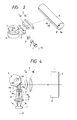
- Figure 3 is a perspective view of the essential portions of an embodiment of the plural-beam scanning optical apparatus of the present invention
- Figure 4 is a schematic view of the essential portions of the Figure 3 embodiment in the main scanning cross-section thereof.
- the main scanning cross-section refers to a light beam cross-section formed with the lapse of time by a light beam deflected by a deflecting surface 4a.
- the reference numeral 1 designates light source means having a plurality of light emitting portions 1 a and 1 and comprising, for example, a semiconductor laser array or the like.
- the plurality of light emitting portions are disposed in the same direction as the main scanning direction or in an oblique direction differing from a direction perpendicular to the main scanning direction.
- Light beams consisting chiefly of these central rays h a and h b pass as parallel light beams through the condensing lens 2 (the central rays h a and h b pass through the focus F of the condensing lens 2), and pass through a cylindrical lens 3 having refractive power in the sub-scanning direction containing the optical axis g and orthogonal to the main scanning direction, and thereafter pass through a stop 7 which limits chiefly the light beams in the main scanning direction and are incident on the deflecting surface 4a of a light deflector 4. If there is not the stop 7 at this time, the central rays h a and h b of the respective light beams will be incident on and reflected by positions Pa and Pb spaced apart from each other on the deflecting surface 4a.
- the stop 7 is provided at a predetermined position spaced apart from the deflecting surface 4a as will be described later, whereby the positions of the central rays of the light beams incident on the deflecting surface 4a are changed so that the central rays may be incident on and reflected by substantially the same position on the deflecting surface 4a.
- the stop 7 being provided, the light beams are limited in the main scanning cross-section and the central rays are changed from h a and h b before entering the stop 7 into rays j a and j b passing through the center of the stop 7.
- the central rays j a and j b approach each other on the deflecting surface 4a as indicated by positions Qa and Qb and moreover, are incident on and reflected by the vicinity of the incidence positions of the rays on the optical axis g of the condensing lens 2.
- the cylindrical lens 3 forms linear images in the main scanning cross-section near the deflecting surface 4a from the light beams emitted from the light emitting portions 11 a and 11 b.
- the light beams reflected by the deflecting surface 4a are imaged on the surface (the scanned surface) 6 of a photosensitive drum 8 or the like by a scanning lens system 5 comprising an anamorphic system as a second optical system having different refractive powers in the main scanning direction and the sub-scanning direction.
- the scanning lens system 5 comprises a spherical lens 5a and a toric lens 5b having different refractive powers in the main scanning cross-section and the sub-scanning cross-section containing the optical axis and orthogonal to the main scanning cross-section and having a toric surface, and has an f-e characteristic in the main scanning cross-section.
- the light deflector 4 is rotated by driving means 9 such as a motor, whereby the scanned surface 6 of the photosensitive drum 8 which is a recording medium is optically scanned by two light spots 6a and 6b. Therewith, the photosensitive drum 8 is rotated in the direction of arrow 8a, whereby the scanned surface 6 is optically scanned at equal speeds in the sub-scanning direction by the two light spots 6a and 6b.
- driving means 9 such as a motor
- the deflecting surface 4a and the scanned surface 6 are in substantially conjugate relationship with each other, and in the main scanning cross-section, light output portions 11 a, 11 b and the scanned surface 6 are in substantially conjugate relationship with each other.
- the number of the light emitting portions of the light source means 1 is n and the pitch thereof is d and the distance from the stop 7 to the reference position on the deflecting surface of the light deflector 4 (the position in which the ray on the optical axis g is incident on the deflecting surface positioned when in the main scanning cross-section, the light beam is incident on the central portion of the scanning range of the scanned surface) is L and the focal length of the condensing lens 2 for collimating the divergent light beams from the light source means 1 is f, the distance a is
- the stop 7 is provided between the deflecting surface 4a and the condensing lens 2 so as to achieve
- each element is appropriately set in this manner, whereby the diameter of the imaged spots of the light beams on the scanned surface can be placed within the depth of focus of the scanning lens system 5 and thus, highly dense and highly accurate scanning is made possible.
- the light deflector is substantially of the same size as that when a single light beam is used. Thereby, high-speed scanning is made possible without the load to the motor or the like being increased.
- the light source means 1 may have more than two light emitting portions and an effect similar to that previously described will be obtained.
- each element is set as described above, whereby when a scanned surface is scanned by a plurality of light beams at a time by the use of light source means such as a semiconductor laser array, each light beam is focused well on the scanned surface and highly dense and highly accurate scanning is possible and use may be made of a light deflector of substantially the same size as that when a single light beam is used, and high-speed scanning is possible.
- light source means such as a semiconductor laser array
- a plural-beam scanning optical apparatus comprises light source means having a plurality of light emitting portions, a first optical system for converting a plurality of divergent light beams from the light source means into parallel light beams, a light deflector for deflecting the plurality of light beams from the first optical system, a stop disposed between the first optical system and the light deflector, and a second optical system for condensing the plurality of light beams deflected by the light deflector on a scanned surface.
- the plurality of light emitting portions are arranged in a direction oblique with respect to the main scanning direction of the light beams on the scanned surface.
- the apparatus satisfies the following condition: where n is the number of the plurality of light emitting portions, d is the pitch thereof, L is the distance from a reference position on the deflecting surface of the light deflector to the stop, and f is the focal length of the first optical system.
Landscapes
- Engineering & Computer Science (AREA)
- Multimedia (AREA)
- Signal Processing (AREA)
- Physics & Mathematics (AREA)
- General Physics & Mathematics (AREA)
- Optics & Photonics (AREA)
- Mechanical Optical Scanning Systems (AREA)
- Facsimile Scanning Arrangements (AREA)
- Dot-Matrix Printers And Others (AREA)
- Laser Beam Printer (AREA)
- Exposure Or Original Feeding In Electrophotography (AREA)
Abstract
where n is the number of the plurality of light emitting portions, d is the pitch thereof, L is the distance from a reference position on the deflecting surface of the light deflector to the stop, and f is the focal length of the first optical system.
Description
- This invention relates to a plural-beam scanning optical apparatus, and particularly to a plural-beam scanning optical apparatus suitable for use in an apparatus such as a laser beam printer (L 13P) in which use is made of light source means having a plurality of light emitting portions and a plurality of light beams emitted from said light source means are directed to the surface of a photosensitive medium which is a scanned surface through a light deflector such as a rotatable polygonal mirror, whereby the surface of the photosensitive medium is scanned by the plurality of light beams at a time to effect, for example, the formation of image information.
- A so-called plural-beam scanning optical system designed to collectively scan the surface of a photosensitive medium which is a scanned surface by a plurality of light beams which can be optically modulated independently of one another has heretofore been proposed, for example, in Japanese Laid-Open Patent Application No. 51-158251.
- Generally, to obtain a good quality of image with a high resolving power when a scanned surface is scanned by a plurality of light beams to thereby form an image, it is necessary to make the spot diameter of the light beams on the scanned surface small and densely form the spots of the light beams in the sub-scanning direction.
- Generally, in a plural-beam scanning optical system, in order to make the spots in the sub-scanning direction dense, use is often made of light source means having a semiconductor laser array is disposed obliquely with respect to the main scanning direction. Such a scanning apparatus is disclosed in U.S. Patent No. 4,624,555.
- Figure 1 of the accompanying drawings is a schematic view of the essential portions of a plural-beam scanning optical apparatus according to the prior art.
- In Figure 1, the
reference numeral 11 designates light source means such as a semiconductor laser array. From a plurality oflight emitting portions condensing lens 12. These central rays ha and hb pass through the focus F of thecondensing lens 12, and pass through acylindrical lens 13 having refractive power in the sub-scanning direction, and thereafter are incident on thedeflecting surface 14a of alight deflector 14. - By this
cylindrical lens 13, the light beams emitted from thelight emitting portions condensing lens 12 are formed as linear images in the main scanning cross-section near thedeflecting surface 14a. At this time, the central rays ha and hb from thelight emitting portions deflecting surface 14a at locations thereon spaced apart from each other in the direction of deflection of the light beams by the deflecting surface. - The light beams reflected by the deflecting
surface 14a are imaged on the scannedsurface 16 of a scanned medium such as a photosensitive member by ascanning lens system 15 comprising an anamorphic system. - Figure 2 of the accompanying drawings is a schematic view showing the optical path in the sub-scanning cross-section from the
light deflector 14 to the scannedsurface 16. As indicated by solid lines in Figure 2, thescanning lens system 15 is designed such that thedeflecting surface 14a and the scannedsurface 16 are in substantially conjugate relationship with each other in the sub-scanning cross-section. - In the plural-beam scanning optical apparatus shown in Figure 1, the central rays ha and hb emitted from the
light emitting portions deflecting surface 14a at locations thereon spaced apart from each other, as previously described. - That is, of the center positions of the plurality of linear images on the
deflecting surface 14a formed by thecylindrical lens 13, the center position of only the linear image corresponding to one of the plurality of light emitting portions can be installed at a desired location, for example, on the deflecting surface. However, the center position of the other linear image becomes spaced apart from the desired location. - That is, like the optical path indicated by broken lines in Figure 2, the other linear image is formed at a location 14b deviating from the
deflecting surface 14a. The center position Pa of the deviating linear image at this time is not imaged on the scannedsurface 16, but is imaged at a point Pb spaced apart from the scannedsurface 16, by thescanning lens system 15. That is, the deviating linear image becomes defocused on the scannedsurface 16. The defocus amount at this time becomes greater as thelight deflector 14 is rotated. - That is, there arises a problem that the spot diamter of the light beams on the scanned
surface 16 increases and highly accurate optical scanning becomes impossible. - Also, as previously described, the light beams emitted from the
light emitting portions surface 14a at locations thereon spaced apart from each other and are reflected and deflected, and this has led to a problem that as compared with a scanning optical apparatus using a single light beam, the deflecting surface must be made large and the deflector becomes correspondingly bulky and high-speed scanning at high accuracy becomes difficult. - The present invention has as its object the provision of a plural-beam scanning optical apparatus in which when a scanned surface is scanned by a plurality of light beams from light source means such as a semiconductor laser array, the light beams are well focused on the scanned surface and which is capable of scanning at high density and high accuracy and may use a light deflector of substantially the same size as in a case where a single light beam is used and which is capable of high-speed scanning.
- The plural-beam scanning optical apparatus of the present invention is characterized in that a plurality of light beams emitted from light source means having a plurality of light emitting portions capable of effecting light modulation independently of one another are collimated by a first optical system and directed to a light deflector through a stop, and the light beams deflected by said light deflector are directed onto a scanned surface by a second optical system, and when said scanned surface is optically scanned by said plurality of light beams at a time, said plurality of light emitting portions are arranged in a direction oblique with respect to the main scanning direction of the light beams an said scanned surface, and said plural-beam scanning optical apparatus satisfies the following condition:

where n is the number of said plurality of light emitting portions, d is the pitch thereof, L is the distance from the reference position of the deflecting surface of said light deflector, and f is the focal length of said first optical system. - The present invention is further characterized in that an anamorphic lens having refractive power in the sub-scanning direction is disposed in the optical path between said first optical system and said light deflector so that in the sub-scanning cross-section, the light beams from said first optical system may be condensed on the deflecting surface of said light deflector, and said second optical system is comprised of an anamorphic system so that in the sub-scanning cross-section, said deflecting surface and said scanned surface may be in substantially conjugate relationship with each other and an f-e characteristic may be had in the main scanning cross-section.
-
- Figure 1 is a schematic view of the essential portions of a plural-beam scanning optical apparatus according to the prior art in the main scanning cross-section thereof.
- Figure 2 is a schematic view of some portions of Figure 1 in the sub-scanning cross-section.
- Figure 3 is a perspective view of the essential portions of a plural-beam scanning optical apparatus according to an embodiment of the present invention.
- Figure 4 is a schematic view of the essential portions of Figure 3 in the main scanning cross-section.
- Figure 3 is a perspective view of the essential portions of an embodiment of the plural-beam scanning optical apparatus of the present invention, and Figure 4 is a schematic view of the essential portions of the Figure 3 embodiment in the main scanning cross-section thereof. The main scanning cross-section refers to a light beam cross-section formed with the lapse of time by a light beam deflected by a deflecting
surface 4a. - In these figures, the reference numeral 1 designates light source means having a plurality of
light emitting portions 1 a and 1 and comprising, for example, a semiconductor laser array or the like. Thelight emitting portions 1 a and 1 are disposed in a direction oblique with respect to the main scanning direction in which light beams are scanned, and the spacing d therebetween is d = 100 am. Divergent light beams are emitted from the plurality oflight emitting portions - The reference characters ha and hb denote central rays emitted from the
light emitting portions cylindrical lens 3 having refractive power in the sub-scanning direction containing the optical axis g and orthogonal to the main scanning direction, and thereafter pass through astop 7 which limits chiefly the light beams in the main scanning direction and are incident on the deflectingsurface 4a of a light deflector 4. If there is not thestop 7 at this time, the central rays ha and hb of the respective light beams will be incident on and reflected by positions Pa and Pb spaced apart from each other on thedeflecting surface 4a. - So, in the present embodiment, the
stop 7 is provided at a predetermined position spaced apart from thedeflecting surface 4a as will be described later, whereby the positions of the central rays of the light beams incident on thedeflecting surface 4a are changed so that the central rays may be incident on and reflected by substantially the same position on thedeflecting surface 4a. - That is, by the
stop 7 being provided, the light beams are limited in the main scanning cross-section and the central rays are changed from ha and hb before entering thestop 7 into rays ja and jb passing through the center of thestop 7. - Thereby, the central rays ja and jb approach each other on the
deflecting surface 4a as indicated by positions Qa and Qb and moreover, are incident on and reflected by the vicinity of the incidence positions of the rays on the optical axis g of thecondensing lens 2. - The
cylindrical lens 3 forms linear images in the main scanning cross-section near thedeflecting surface 4a from the light beams emitted from thelight emitting portions - The light beams reflected by the deflecting
surface 4a are imaged on the surface (the scanned surface) 6 of aphotosensitive drum 8 or the like by ascanning lens system 5 comprising an anamorphic system as a second optical system having different refractive powers in the main scanning direction and the sub-scanning direction. Thescanning lens system 5 comprises aspherical lens 5a and atoric lens 5b having different refractive powers in the main scanning cross-section and the sub-scanning cross-section containing the optical axis and orthogonal to the main scanning cross-section and having a toric surface, and has an f-e characteristic in the main scanning cross-section. - The light deflector 4 is rotated by driving means 9 such as a motor, whereby the scanned
surface 6 of thephotosensitive drum 8 which is a recording medium is optically scanned by twolight spots photosensitive drum 8 is rotated in the direction ofarrow 8a, whereby the scannedsurface 6 is optically scanned at equal speeds in the sub-scanning direction by the twolight spots - In the present embodiment, in the sub-scanning cross-section, the
deflecting surface 4a and the scannedsurface 6 are in substantially conjugate relationship with each other, and in the main scanning cross-section,light output portions surface 6 are in substantially conjugate relationship with each other. - Each element in the present embodiment will now be described.
- Considering with reference to Figure 2, when the distance from the optical axis g to the reflecting point on the
deflecting surface 14a in a direction perpendicular to the optical axis g is a and the magnification of thescanning lens system 15 in the sub-scanning direction is ;8, the defocus amount A on the scanned surface is in the relation that -

- When in the plural-beam scanning optical apparatus of the present invention shown in Figure 3, the number of the light emitting portions of the light source means 1 is n and the pitch thereof is d and the distance from the
stop 7 to the reference position on the deflecting surface of the light deflector 4 (the position in which the ray on the optical axis g is incident on the deflecting surface positioned when in the main scanning cross-section, the light beam is incident on the central portion of the scanning range of the scanned surface) is L and the focal length of thecondensing lens 2 for collimating the divergent light beams from the light source means 1 is f, the distance a is
- Also, when for example, in the scanning optical apparatus of a laser beam printer or the like, the allowable amount of the depth of focus on the scanned surface is considered, it is rare that if the distance a is approximately a 0.2, the aforementioned defocus amount will not adversely affect the image. So, in the present embodiment, as previously described, the
stop 7 is provided between thedeflecting surface 4a and thecondensing lens 2 so as to achieve
- In the present embodiment, L = 20 mm, from which the distance a is a = 0.1 mm. This distance a is about 1/4 as compared with a case where the
stop 7 is not provided. - In the present embodiment, each element is appropriately set in this manner, whereby the diameter of the imaged spots of the light beams on the scanned surface can be placed within the depth of focus of the
scanning lens system 5 and thus, highly dense and highly accurate scanning is made possible. Also, the light deflector is substantially of the same size as that when a single light beam is used. Thereby, high-speed scanning is made possible without the load to the motor or the like being increased. - Further, in the present embodiment, if each element is set so as to satisfy the aforementioned conditional expression (1), the light source means 1 may have more than two light emitting portions and an effect similar to that previously described will be obtained.
- According to the present invention, there can be achieved a plural-beam scanning optical apparatus in which each element is set as described above, whereby when a scanned surface is scanned by a plurality of light beams at a time by the use of light source means such as a semiconductor laser array, each light beam is focused well on the scanned surface and highly dense and highly accurate scanning is possible and use may be made of a light deflector of substantially the same size as that when a single light beam is used, and high-speed scanning is possible.
- A plural-beam scanning optical apparatus comprises light source means having a plurality of light emitting portions, a first optical system for converting a plurality of divergent light beams from the light source means into parallel light beams, a light deflector for deflecting the plurality of light beams from the first optical system, a stop disposed between the first optical system and the light deflector, and a second optical system for condensing the plurality of light beams deflected by the light deflector on a scanned surface. The plurality of light emitting portions are arranged in a direction oblique with respect to the main scanning direction of the light beams on the scanned surface. The apparatus satisfies the following condition:

where n is the number of the plurality of light emitting portions, d is the pitch thereof, L is the distance from a reference position on the deflecting surface of the light deflector to the stop, and f is the focal length of the first optical system.
Claims (4)
where n is the number of said plurality of light emitting portions, d is the pitch thereof, L is the distance from a reference position on the deflecting surface of said light deflector to said stop, and f is the focal length of said first optical system.
where n is the number of said plurality of light emitting portions, d is the pitch thereof, L is the distance from a reference position on the deflecting surface of said light deflector to said stop, and f is the focal length of said first optical system.
Applications Claiming Priority (2)
| Application Number | Priority Date | Filing Date | Title |
|---|---|---|---|
| JP217868/91 | 1991-08-03 | ||
| JP3217868A JP2524567B2 (en) | 1991-08-03 | 1991-08-03 | Multiple beam scanning optics |
Publications (3)
| Publication Number | Publication Date |
|---|---|
| EP0526846A2 true EP0526846A2 (en) | 1993-02-10 |
| EP0526846A3 EP0526846A3 (en) | 1993-11-03 |
| EP0526846B1 EP0526846B1 (en) | 1997-10-08 |
Family
ID=16711032
Family Applications (1)
| Application Number | Title | Priority Date | Filing Date |
|---|---|---|---|
| EP92113061A Expired - Lifetime EP0526846B1 (en) | 1991-08-03 | 1992-07-31 | Plural-beam scanning optical apparatus |
Country Status (4)
| Country | Link |
|---|---|
| US (1) | US5463418A (en) |
| EP (1) | EP0526846B1 (en) |
| JP (1) | JP2524567B2 (en) |
| DE (1) | DE69222598T2 (en) |
Cited By (5)
| Publication number | Priority date | Publication date | Assignee | Title |
|---|---|---|---|---|
| US5438450A (en) * | 1992-12-29 | 1995-08-01 | Canon Kabushiki Kaisha | Optical scanning apparatus |
| DE19621138A1 (en) * | 1995-05-24 | 1996-11-28 | Ricoh Kk | Optical scanning device for digital copier or laser printer |
| DE19655166C2 (en) * | 1995-05-24 | 2003-04-10 | Ricoh Kk | Optical scanning device for digital copier or laser printer |
| DE19703601B4 (en) * | 1996-01-31 | 2005-08-04 | Pentax Corp. | scanning |
| WO2005076053A1 (en) * | 2004-02-06 | 2005-08-18 | Hewlett-Packard Indigo B.V. | Scanner systems |
Families Citing this family (12)
| Publication number | Priority date | Publication date | Assignee | Title |
|---|---|---|---|---|
| JP3222023B2 (en) * | 1994-11-09 | 2001-10-22 | 株式会社東芝 | Optical scanning device |
| JP3990008B2 (en) * | 1997-10-20 | 2007-10-10 | コニカミノルタビジネステクノロジーズ株式会社 | Multi-beam scanning device |
| US6064417A (en) * | 1998-03-31 | 2000-05-16 | Eastman Kodak Company | Laser printer using multiple sets of lasers with multiple wavelengths |
| DE19829986C1 (en) * | 1998-07-04 | 2000-03-30 | Lis Laser Imaging Systems Gmbh | Process for direct exposure of circuit board substrates |
| US6359640B1 (en) | 2000-04-28 | 2002-03-19 | Lexmark International, Inc. | Method and apparatus for minimizing visual artifacts resulting from laser scan process direction position errors |
| JP4541523B2 (en) * | 2000-10-10 | 2010-09-08 | キヤノン株式会社 | Multi-beam optical scanning optical system, multi-beam optical scanning device, and image forming apparatus |
| JP3825995B2 (en) | 2001-06-27 | 2006-09-27 | キヤノン株式会社 | Optical scanning device, multi-beam scanning device, and image forming apparatus using the same |
| US20030063663A1 (en) * | 2001-10-01 | 2003-04-03 | Bryant Paul Henry | Multistage equalizer that corrects for linear and nonlinear distortion in a digitally-modulated signal |
| JP3667286B2 (en) | 2002-02-20 | 2005-07-06 | キヤノン株式会社 | Optical scanning apparatus, image forming apparatus, and color image forming apparatus |
| US8294062B2 (en) * | 2007-08-20 | 2012-10-23 | Universal Laser Systems, Inc. | Laser beam positioning systems for material processing and methods for using such systems |
| JP5489612B2 (en) * | 2008-11-10 | 2014-05-14 | キヤノン株式会社 | Scanning optical device and image forming apparatus using the same |
| JP5079060B2 (en) * | 2010-08-02 | 2012-11-21 | シャープ株式会社 | Optical scanning apparatus and image forming apparatus |
Citations (4)
| Publication number | Priority date | Publication date | Assignee | Title |
|---|---|---|---|---|
| DE2917163A1 (en) * | 1978-04-28 | 1979-11-08 | Canon Kk | OPTICAL RECORDING SYSTEM |
| DE3314402A1 (en) * | 1982-04-22 | 1983-10-27 | Canon K.K., Tokyo | Device for scanning a multiplicity of beams |
| GB2138162A (en) * | 1980-02-06 | 1984-10-17 | Canon Kk | Scanning optical system |
| EP0388981A2 (en) * | 1989-03-23 | 1990-09-26 | Canon Kabushiki Kaisha | Optical scanning apparatus |
Family Cites Families (3)
| Publication number | Priority date | Publication date | Assignee | Title |
|---|---|---|---|---|
| JPS6033019B2 (en) * | 1978-06-05 | 1985-07-31 | 株式会社日立製作所 | optical recording device |
| JPS60253027A (en) * | 1984-05-29 | 1985-12-13 | Canon Inc | Optical information processor |
| JPS6187125A (en) * | 1984-09-20 | 1986-05-02 | Canon Inc | Projecting device for exposing slit |
-
1991
- 1991-08-03 JP JP3217868A patent/JP2524567B2/en not_active Expired - Lifetime
-
1992
- 1992-07-31 DE DE69222598T patent/DE69222598T2/en not_active Expired - Lifetime
- 1992-07-31 EP EP92113061A patent/EP0526846B1/en not_active Expired - Lifetime
-
1993
- 1993-05-04 US US08/056,740 patent/US5463418A/en not_active Expired - Lifetime
Patent Citations (4)
| Publication number | Priority date | Publication date | Assignee | Title |
|---|---|---|---|---|
| DE2917163A1 (en) * | 1978-04-28 | 1979-11-08 | Canon Kk | OPTICAL RECORDING SYSTEM |
| GB2138162A (en) * | 1980-02-06 | 1984-10-17 | Canon Kk | Scanning optical system |
| DE3314402A1 (en) * | 1982-04-22 | 1983-10-27 | Canon K.K., Tokyo | Device for scanning a multiplicity of beams |
| EP0388981A2 (en) * | 1989-03-23 | 1990-09-26 | Canon Kabushiki Kaisha | Optical scanning apparatus |
Cited By (6)
| Publication number | Priority date | Publication date | Assignee | Title |
|---|---|---|---|---|
| US5438450A (en) * | 1992-12-29 | 1995-08-01 | Canon Kabushiki Kaisha | Optical scanning apparatus |
| DE19621138A1 (en) * | 1995-05-24 | 1996-11-28 | Ricoh Kk | Optical scanning device for digital copier or laser printer |
| DE19621138C2 (en) * | 1995-05-24 | 2000-11-16 | Ricoh Kk | Multi-beam scanning device |
| DE19655166C2 (en) * | 1995-05-24 | 2003-04-10 | Ricoh Kk | Optical scanning device for digital copier or laser printer |
| DE19703601B4 (en) * | 1996-01-31 | 2005-08-04 | Pentax Corp. | scanning |
| WO2005076053A1 (en) * | 2004-02-06 | 2005-08-18 | Hewlett-Packard Indigo B.V. | Scanner systems |
Also Published As
| Publication number | Publication date |
|---|---|
| JPH0534613A (en) | 1993-02-12 |
| JP2524567B2 (en) | 1996-08-14 |
| EP0526846B1 (en) | 1997-10-08 |
| EP0526846A3 (en) | 1993-11-03 |
| DE69222598T2 (en) | 1998-03-05 |
| DE69222598D1 (en) | 1997-11-13 |
| US5463418A (en) | 1995-10-31 |
Similar Documents
| Publication | Publication Date | Title |
|---|---|---|
| US4390235A (en) | Multibeam scanning apparatus provided with a function of changing magnification | |
| US5463418A (en) | Plural-beam scanning optical apparatus | |
| US4123135A (en) | Optical system for rotating mirror line scanning apparatus | |
| US5245462A (en) | Laser beam scanning apparatus | |
| US5550668A (en) | Multispot polygon ROS with maximized line separation depth of focus | |
| GB1581275A (en) | Flying-spot scanning system | |
| US5510826A (en) | Optical scanning apparatus | |
| US4571021A (en) | Plural-beam scanning apparatus | |
| US5028103A (en) | Optical scanning apparatus | |
| US6172787B1 (en) | Laser beam scanning optical apparatus | |
| US6268877B1 (en) | Scanning optical device featuring optical system image magnifications in main and subscanning directions within a prescribed range | |
| KR19980019037A (en) | A multi-beam scanning apparatus (MULTI-BEAM SCANNING APPARATUS WITH CONTROLLED SCAN LINE BOW) | |
| US4565421A (en) | Plural-beam scanning apparatus | |
| US5008686A (en) | Optical scanning device for scanning a predetermined surface with a plurality of light beams | |
| US5200766A (en) | Optical scanning device used for image forming apparatus | |
| US5278691A (en) | Symmetrical overfilled polygon laser scanner | |
| JPH0152728B2 (en) | ||
| JPH09138363A (en) | Multibeam scanner | |
| JP2783481B2 (en) | Inner drum scanning type recording device | |
| JPH0618802A (en) | Optical scanning device | |
| US6570696B2 (en) | Optical system for scanning and optical scanning apparatus | |
| JP3198750B2 (en) | Optical scanning device | |
| JP2000180749A (en) | Optical scanner | |
| JP2811988B2 (en) | Optical scanning device in image forming apparatus | |
| JPS5878117A (en) | Multibeam recording device |
Legal Events
| Date | Code | Title | Description |
|---|---|---|---|
| PUAI | Public reference made under article 153(3) epc to a published international application that has entered the european phase |
Free format text: ORIGINAL CODE: 0009012 |
|
| AK | Designated contracting states |
Kind code of ref document: A2 Designated state(s): DE FR GB IT |
|
| PUAL | Search report despatched |
Free format text: ORIGINAL CODE: 0009013 |
|
| AK | Designated contracting states |
Kind code of ref document: A3 Designated state(s): DE FR GB IT |
|
| 17P | Request for examination filed |
Effective date: 19940321 |
|
| 17Q | First examination report despatched |
Effective date: 19950517 |
|
| GRAG | Despatch of communication of intention to grant |
Free format text: ORIGINAL CODE: EPIDOS AGRA |
|
| GRAH | Despatch of communication of intention to grant a patent |
Free format text: ORIGINAL CODE: EPIDOS IGRA |
|
| GRAH | Despatch of communication of intention to grant a patent |
Free format text: ORIGINAL CODE: EPIDOS IGRA |
|
| GRAA | (expected) grant |
Free format text: ORIGINAL CODE: 0009210 |
|
| AK | Designated contracting states |
Kind code of ref document: B1 Designated state(s): DE FR GB IT |
|
| ITF | It: translation for a ep patent filed | ||
| REF | Corresponds to: |
Ref document number: 69222598 Country of ref document: DE Date of ref document: 19971113 |
|
| ET | Fr: translation filed | ||
| PLBE | No opposition filed within time limit |
Free format text: ORIGINAL CODE: 0009261 |
|
| STAA | Information on the status of an ep patent application or granted ep patent |
Free format text: STATUS: NO OPPOSITION FILED WITHIN TIME LIMIT |
|
| 26N | No opposition filed | ||
| REG | Reference to a national code |
Ref country code: GB Ref legal event code: IF02 |
|
| PGFP | Annual fee paid to national office [announced via postgrant information from national office to epo] |
Ref country code: DE Payment date: 20100731 Year of fee payment: 19 Ref country code: FR Payment date: 20100806 Year of fee payment: 19 Ref country code: IT Payment date: 20100719 Year of fee payment: 19 |
|
| PGFP | Annual fee paid to national office [announced via postgrant information from national office to epo] |
Ref country code: GB Payment date: 20100726 Year of fee payment: 19 |
|
| GBPC | Gb: european patent ceased through non-payment of renewal fee |
Effective date: 20110731 |
|
| REG | Reference to a national code |
Ref country code: FR Ref legal event code: ST Effective date: 20120330 |
|
| PG25 | Lapsed in a contracting state [announced via postgrant information from national office to epo] |
Ref country code: FR Free format text: LAPSE BECAUSE OF NON-PAYMENT OF DUE FEES Effective date: 20110801 Ref country code: DE Free format text: LAPSE BECAUSE OF NON-PAYMENT OF DUE FEES Effective date: 20120201 |
|
| REG | Reference to a national code |
Ref country code: DE Ref legal event code: R119 Ref document number: 69222598 Country of ref document: DE Effective date: 20120201 |
|
| PG25 | Lapsed in a contracting state [announced via postgrant information from national office to epo] |
Ref country code: IT Free format text: LAPSE BECAUSE OF NON-PAYMENT OF DUE FEES Effective date: 20110731 |
|
| PG25 | Lapsed in a contracting state [announced via postgrant information from national office to epo] |
Ref country code: GB Free format text: LAPSE BECAUSE OF NON-PAYMENT OF DUE FEES Effective date: 20110731 |