EP0525972B1 - Lawn mower - Google Patents
Lawn mower Download PDFInfo
- Publication number
- EP0525972B1 EP0525972B1 EP92305804A EP92305804A EP0525972B1 EP 0525972 B1 EP0525972 B1 EP 0525972B1 EP 92305804 A EP92305804 A EP 92305804A EP 92305804 A EP92305804 A EP 92305804A EP 0525972 B1 EP0525972 B1 EP 0525972B1
- Authority
- EP
- European Patent Office
- Prior art keywords
- impeller
- braking
- brake
- rotation
- motor
- Prior art date
- Legal status (The legal status is an assumption and is not a legal conclusion. Google has not performed a legal analysis and makes no representation as to the accuracy of the status listed.)
- Expired - Lifetime
Links
- 229910000831 Steel Inorganic materials 0.000 description 3
- 230000000694 effects Effects 0.000 description 3
- 239000010959 steel Substances 0.000 description 3
- 229910000760 Hardened steel Inorganic materials 0.000 description 1
- 230000033228 biological regulation Effects 0.000 description 1
- 238000006073 displacement reaction Methods 0.000 description 1
- 230000006698 induction Effects 0.000 description 1
- 238000004519 manufacturing process Methods 0.000 description 1
Images


Classifications
-
- A—HUMAN NECESSITIES
- A01—AGRICULTURE; FORESTRY; ANIMAL HUSBANDRY; HUNTING; TRAPPING; FISHING
- A01D—HARVESTING; MOWING
- A01D34/00—Mowers; Mowing apparatus of harvesters
- A01D34/01—Mowers; Mowing apparatus of harvesters characterised by features relating to the type of cutting apparatus
- A01D34/412—Mowers; Mowing apparatus of harvesters characterised by features relating to the type of cutting apparatus having rotating cutters
- A01D34/63—Mowers; Mowing apparatus of harvesters characterised by features relating to the type of cutting apparatus having rotating cutters having cutters rotating about a vertical axis
- A01D34/67—Mowers; Mowing apparatus of harvesters characterised by features relating to the type of cutting apparatus having rotating cutters having cutters rotating about a vertical axis hand-guided by a walking operator
- A01D34/68—Mowers; Mowing apparatus of harvesters characterised by features relating to the type of cutting apparatus having rotating cutters having cutters rotating about a vertical axis hand-guided by a walking operator with motor driven cutters or wheels
- A01D34/6806—Driving mechanisms
- A01D34/6812—Braking or clutching mechanisms
-
- F—MECHANICAL ENGINEERING; LIGHTING; HEATING; WEAPONS; BLASTING
- F04—POSITIVE - DISPLACEMENT MACHINES FOR LIQUIDS; PUMPS FOR LIQUIDS OR ELASTIC FLUIDS
- F04D—NON-POSITIVE-DISPLACEMENT PUMPS
- F04D27/00—Control, e.g. regulation, of pumps, pumping installations or pumping systems specially adapted for elastic fluids
- F04D27/008—Stop safety or alarm devices, e.g. stop-and-go control; Disposition of check-valves
-
- F—MECHANICAL ENGINEERING; LIGHTING; HEATING; WEAPONS; BLASTING
- F16—ENGINEERING ELEMENTS AND UNITS; GENERAL MEASURES FOR PRODUCING AND MAINTAINING EFFECTIVE FUNCTIONING OF MACHINES OR INSTALLATIONS; THERMAL INSULATION IN GENERAL
- F16D—COUPLINGS FOR TRANSMITTING ROTATION; CLUTCHES; BRAKES
- F16D59/00—Self-acting brakes, e.g. coming into operation at a predetermined speed
- F16D59/02—Self-acting brakes, e.g. coming into operation at a predetermined speed spring-loaded and adapted to be released by mechanical, fluid, or electromagnetic means
-
- H—ELECTRICITY
- H02—GENERATION; CONVERSION OR DISTRIBUTION OF ELECTRIC POWER
- H02K—DYNAMO-ELECTRIC MACHINES
- H02K7/00—Arrangements for handling mechanical energy structurally associated with dynamo-electric machines, e.g. structural association with mechanical driving motors or auxiliary dynamo-electric machines
- H02K7/10—Structural association with clutches, brakes, gears, pulleys or mechanical starters
- H02K7/12—Structural association with clutches, brakes, gears, pulleys or mechanical starters with auxiliary limited movement of stators, rotors or core parts, e.g. rotors axially movable for the purpose of clutching or braking
- H02K7/125—Structural association with clutches, brakes, gears, pulleys or mechanical starters with auxiliary limited movement of stators, rotors or core parts, e.g. rotors axially movable for the purpose of clutching or braking magnetically influenced
-
- A—HUMAN NECESSITIES
- A01—AGRICULTURE; FORESTRY; ANIMAL HUSBANDRY; HUNTING; TRAPPING; FISHING
- A01D—HARVESTING; MOWING
- A01D2101/00—Lawn-mowers
-
- Y—GENERAL TAGGING OF NEW TECHNOLOGICAL DEVELOPMENTS; GENERAL TAGGING OF CROSS-SECTIONAL TECHNOLOGIES SPANNING OVER SEVERAL SECTIONS OF THE IPC; TECHNICAL SUBJECTS COVERED BY FORMER USPC CROSS-REFERENCE ART COLLECTIONS [XRACs] AND DIGESTS
- Y10—TECHNICAL SUBJECTS COVERED BY FORMER USPC
- Y10S—TECHNICAL SUBJECTS COVERED BY FORMER USPC CROSS-REFERENCE ART COLLECTIONS [XRACs] AND DIGESTS
- Y10S56/00—Harvesters
- Y10S56/04—Friction drive
Definitions
- the present invention relates to an improved braking system which is particularly suitable for use with a lawn mower of the rotary type in which a blade and an impeller are rotated about a common axis by a motor, which may be an electric motor or a petrol motor.
- a motor which may be an electric motor or a petrol motor.
- Braking systems which are currently available for use on mowers of this type include electromechanical systems which are spring loaded brake systems comprising a brake pad and a brake disc, the spring urging the pad and disc into braking contact and being opposed by the action of a solenoid.
- Braking systems for electric motors comprise an electromagnetically releasable spring actuated brake with a braking surface, a brake disc driven in rotation, a release device non-rotatably secured to the braking surface, and an armature mounted non-rotatably and so as to be capable of axial displacement between the brake disc and the release device, and biased by springs against the brake disc.
- Such braking systems have been disclosed in connection with motors having substantially horizontally mounted axles to be stopped. In such braking systems, on energising the motor the axle moves to separate the brake disc from its corresponding braking surface. On deactivating the motor, the spring urges the brake disc back into contact with the braking surface.
- FR-A-2 411 503 describes and claims a braking system for a lawn mower, which system comprises
- the invention provides a braking system for a lawn mower, which system comprises
- the braking contact between the brake element and the friction element is released by means of the axial force produced by the pressure differential generated by the impeller.
- means are provided to lift the impeller on start-up of the motor, in order to release the braking contact between the brake element and the friction element.
- the means provided to lift the impeller on start-up of the motor may, for example, be a mechanical system such as an angled drive dog or ball and ramp arrangement, or may be an electromagnetic system such as the electromagnetically releasable spring actuated system described above in connection with the braking of horizontally mounted axles.
- the rotary lawn mower 10 comprises a deck 2 on which a series electric motor 4 is mounted.
- the motor 4 is provided with an output shaft 6 on which is fitted a blade 8 and impeller 12.
- a brake disc 14 is attached by means of screws 16 to the impeller 12.
- the impeller 12 and disc 14 assembly is slidably mounted on the output shaft 6, by means of an adaptor 18, so that the assembly is free to move in an axial direction relative to the shaft 6 but rotates with the shaft 6.
- An annular brake friction plate 20 is secured to a housing 22 of the motor 4.
- Brake friction pads 24 are attached to an inner circular flange portion of the brake friction plate 20.
- a spring 26 is provided to urge the brake disc 14 downwardly into braking contact with the pads 24 on the brake friction plate 20.
- the impeller 12 In operation, as the motor 4 is energised, the impeller 12 is driven by the output shaft 6 and begins to rotate. As the speed of rotation increases, a pressure differential is built up due to the rotation of the impeller 12, and the pressure on the motor side of the impeller 12 falls sharply, tending to draw the assembly comprising the impeller 12 and brake disc 14 towards the motor 4 against the action of the spring 26. This removes the braking contact between the brake disc 14 and brake friction plate 20 so that the impeller 12 and blade 8 are free to rotate.
- the impeller 12 When the motor 4 is switched off, the impeller 12 is no longer driven by the output shaft 6 and the speed of rotation reduces sharply. This has the effect of reducing the pressure differential between the two surfaces of the impeller, equalising the rotational forces on the impeller.
- the force of the spring 26 is no longer opposed by the suction force generated by the rotating impeller 12 and thus urges the brake disc 14 and brake friction plate 20 into braking contact, thus braking the system.
- the mower is provided with means to release the brake on initial start-up of the motor.
- the motor 34 comprises an armature 36 located within a stator 38.
- the armature 36 is mounted so that it is able to move axially with respect to the stator 38.
- Spaced steel discs 40 are mounted to rotate with the armature 36, and friction pads 42 are positioned in the spaces between the steel discs 40.
- the friction pads 42 are fixed in the motor housing 22 against rotation but are free to move axially.
- An impeller 44 is mounted on the output shaft 46 and is urged by a spring 48 away from the armature 36 and associated steel discs 40 and brake pads 42. Needle roller bearings 50 are provided, and allow the shaft to rotate and move freely in the axial direction.
- the magnetic field of the armature 36 is offset relative to that of the stator 38.
- the motor 34 is energised, there is an initial surge in current and hence in the magnetic field.
- the offset arrangement of the magnetic fields of the armature and stator causes the armature to lift relative to the stator and release the braking contact.
- the speed of rotation of the impeller increases and the pressure effects described with respect to the first embodiment of the braking system, come into force.
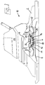
- a third embodiment is shown in Figures 4 and 5.
- Figure 4 shows a deck 62 on which a motor 64 is mounted.
- the motor 64 comprises an output shaft 66 on which is secured an adaptor 68.
- the adaptor 68 comprises a cylindrical body 70 from which extends a sleeve 72.
- In an upper surface 74 of the body 70 are four bearing recesses 76 which support ball bearings 77. Also secured to the upper surface 74 are four axially extending hardened steel pins 78.
- a blade 80 is secured to the shaft 66 for rotation therewith.
- An impeller 82 has a sleeve portion 84 which surrounds the body 70 of the adaptor 68, and is secured by screws 86 to a dished brake disc 88.
- the disc 88 comprises bosses 90 having bores therein which fit over the pins 78. The assembly of impeller 82 and brake disc 88 is thus constrained to rotate with the shaft 66 and adaptor 68, but can move axially relative to them.
- An annular brake friction plate 92 is secured to a housing of the motor 64, and a spring 94 urges the brake disc 88 downwardly into braking contact with brake pads 96 on the brake friction plate 92.
- the recesses 76 in the adaptor 68 each comprise a lower surface 79 and an upwardly inclined ramp surface 81.
- the operation of the third embodiment is essentially similar to that of the first embodiment, save that on the first rotary impulse given to the adaptor 68, the balls 77 are caused to ride up from the lower surfaces 79 up the ramp surfaces 81, whereby to assist in moving the assembly of the impeller 82 and brake disc 88 upwards to release the braking effect between the disc 82 and the friction plate 92.
Landscapes
- Engineering & Computer Science (AREA)
- General Engineering & Computer Science (AREA)
- Mechanical Engineering (AREA)
- Life Sciences & Earth Sciences (AREA)
- Environmental Sciences (AREA)
- Physics & Mathematics (AREA)
- Electromagnetism (AREA)
- Power Engineering (AREA)
- Harvester Elements (AREA)
- Braking Arrangements (AREA)
Description
In such braking systems, on energising the motor the axle moves to separate the brake disc from its corresponding braking surface. On deactivating the motor, the spring urges the brake disc back into contact with the braking surface.
The invention provides a braking system for a lawn mower, which system comprises
Claims (6)
- A braking system for a lawn mower, which system comprises(i) an impeller (12) mounted for rotation about a shaft (6) driven for rotation by a drive system and movable in an axial direction relative to the axis of that shaft;(ii) a brake element (14) mounted for rotation with the impeller (12);(iii) a brake friction element (20) which is restrained from rotation; and(iv)resilient means (26) urging the brake element (14) in an axial direction into braking contact with the friction element (20), characterised in that the impeller (12) is arranged in such a way that the axial force produced by the pressure differential generated by the impeller (12) opposes the resilient means (26) and thereby acts to oppose contact between the brake element (14) and the friction element (20).
- A braking system for a lawn mower according to claim 1 characterised in that the braking contact between the brake element (14) and the friction element (20) is released by means of the axial force produced by the pressure differential generated by the impeller (12).
- A braking system according to claim 1 which further comprises means to lift the impeller on start-up of the motor, in order to release the braking contact between the brake element (14) and the friction element (20).
- A braking system according to claim 3 in which the means to lift the impeller comprises an electromagnetically releasable spring-actuated system.
- A braking system according to claim 3 in which the means to lift the impeller comprises an angled drive dog.
- A braking system according to claim 6 in which the means to lift the impeller comprises a ball and ramp arrangement.
Applications Claiming Priority (2)
| Application Number | Priority Date | Filing Date | Title |
|---|---|---|---|
| GB9114434 | 1991-07-03 | ||
| GB919114434A GB9114434D0 (en) | 1991-07-03 | 1991-07-03 | Lawn mower |
Publications (2)
| Publication Number | Publication Date |
|---|---|
| EP0525972A1 EP0525972A1 (en) | 1993-02-03 |
| EP0525972B1 true EP0525972B1 (en) | 1998-05-27 |
Family
ID=10697798
Family Applications (1)
| Application Number | Title | Priority Date | Filing Date |
|---|---|---|---|
| EP92305804A Expired - Lifetime EP0525972B1 (en) | 1991-07-03 | 1992-06-24 | Lawn mower |
Country Status (5)
| Country | Link |
|---|---|
| US (1) | US5293731A (en) |
| EP (1) | EP0525972B1 (en) |
| CA (1) | CA2072441C (en) |
| DE (1) | DE69225648D1 (en) |
| GB (1) | GB9114434D0 (en) |
Families Citing this family (14)
| Publication number | Priority date | Publication date | Assignee | Title |
|---|---|---|---|---|
| US5570765A (en) * | 1995-06-02 | 1996-11-05 | North American Clutch Corp. | Clutch/brake assembly |
| DE59601548D1 (en) * | 1995-09-30 | 1999-05-06 | Kemper Gmbh Maschf | Mowing device |
| SE505313C2 (en) * | 1996-05-31 | 1997-08-04 | Fhp Elmotor Ab | Braking |
| US6178729B1 (en) * | 1999-04-09 | 2001-01-30 | Laszlo Vastag | Lawn mower with a deck formed with a trap door |
| US6464055B1 (en) * | 2000-07-28 | 2002-10-15 | Honda Giken Kogyo Kabushiki Kaisha | Blade brake and clutch |
| US6487835B2 (en) * | 2001-04-27 | 2002-12-03 | New Holland North America, Inc. | Overload protection for a disc cutterbar |
| US6604347B2 (en) * | 2001-04-27 | 2003-08-12 | New Holland North America, Inc. | Energy absorber for hubs of agricultural disc drive |
| US20030230009A1 (en) * | 2002-06-14 | 2003-12-18 | Chesner Warren Howard | Marine-based platform for dredged solids management |
| CN1300480C (en) * | 2005-02-07 | 2007-02-14 | 常州合力电器有限公司 | Inertial rotation axial braking device for gardening tool |
| JP5614331B2 (en) * | 2011-02-28 | 2014-10-29 | 日立工機株式会社 | Lawn mower |
| CN102388724B (en) * | 2011-08-30 | 2013-07-10 | 浙江亚特电器有限公司 | Mower braking structure |
| CN104170590B (en) * | 2013-05-27 | 2017-06-13 | 苏州金莱克精密机械有限公司 | Electric tool and its motor with improvement brake structure |
| US9373987B2 (en) | 2013-09-11 | 2016-06-21 | Honda Motor Co., Ltd. | Integrated flywheels, systems and methods for electric generation and braking of a general purpose engine |
| US20190059215A1 (en) * | 2017-08-28 | 2019-02-28 | Diamond Mowers Llc | Cutter retention assembly |
Family Cites Families (17)
| Publication number | Priority date | Publication date | Assignee | Title |
|---|---|---|---|---|
| BE718954A (en) * | 1967-08-05 | 1969-01-16 | ||
| US3897678A (en) * | 1971-04-13 | 1975-08-05 | Int Harvester Co | Self actuating mechanism for braking a driven member upon discontinuation of drive thereto |
| US3731472A (en) * | 1972-03-27 | 1973-05-08 | Simplicity Mfg Co Inc | Rotary mower spindle brake |
| CA990229A (en) * | 1972-10-10 | 1976-06-01 | International Harvester Company | Self-actuating mechanism for braking a driven member upon discontinuation of drive thereto |
| US3967438A (en) * | 1975-04-18 | 1976-07-06 | International Harvester Company | Rotary mower spindle assembly |
| DE2751841C3 (en) * | 1977-11-19 | 1981-10-01 | G. Bauknecht Gmbh, 7000 Stuttgart | Squirrel cage motor with friction brake |
| FR2411503A1 (en) * | 1977-12-06 | 1979-07-06 | Normandie Moteurs Electr | ROTATING ELECTRIC MACHINE WITH SELF-BRAKING ROTOR, AND APPARATUS WITH ROTARY CUTTING BODY, INCLUDING SUCH AN ELECTRIC MACHINE |
| JPS591466Y2 (en) * | 1978-02-02 | 1984-01-17 | 本田技研工業株式会社 | self-propelled lawn mower |
| US4286701A (en) * | 1978-09-27 | 1981-09-01 | Warner Electric Brake & Clutch Company | Amplifying clutch |
| JPS6020615B2 (en) * | 1979-10-18 | 1985-05-23 | 日信工業株式会社 | Clutch brake device |
| DE2951563A1 (en) * | 1979-12-21 | 1981-07-02 | Vorwerk & Co Interholding Gmbh, 5600 Wuppertal | BEARING FOR THE ROTOR SHAFT OF ELECTRIC MOTORS WITH BLOWING WHEEL |
| US4372433A (en) * | 1980-04-14 | 1983-02-08 | Briggs & Stratton Corporation | Combination clutch/brake mechanism |
| US4511023A (en) * | 1980-04-28 | 1985-04-16 | Nisshin Kogyo Kabushiki Kaisha | Clutch brake apparatus for farm work machinery or other apparatus |
| AU557549B2 (en) * | 1981-02-06 | 1986-12-24 | Nisshin Kogyo K.K. | Clutch brake arrangement |
| US4388988A (en) * | 1981-05-11 | 1983-06-21 | Warner Electric Brake & Clutch Company | Anti-kickback clutch-brake unit |
| FR2614377B3 (en) * | 1987-04-21 | 1989-07-21 | Peugeot Cycles | CLUTCH AND BRAKE DEVICE FOR DRIVING A ROTARY MEMBER SUCH AS A LAWNMOWER BLADE |
| DE3825114A1 (en) * | 1988-07-23 | 1990-01-25 | Licentia Gmbh | ELECTRIC MOTOR WITH SELF-ACTING BRAKE |
-
1991
- 1991-07-03 GB GB919114434A patent/GB9114434D0/en active Pending
-
1992
- 1992-06-24 DE DE69225648T patent/DE69225648D1/en not_active Expired - Lifetime
- 1992-06-24 EP EP92305804A patent/EP0525972B1/en not_active Expired - Lifetime
- 1992-06-26 CA CA002072441A patent/CA2072441C/en not_active Expired - Lifetime
- 1992-07-01 US US07/907,096 patent/US5293731A/en not_active Expired - Lifetime
Non-Patent Citations (1)
| Title |
|---|
| PATENT ABSTRACTS OF JAPAN vol. 7, no. 163 (M-229)(1308) 16 July 1983 & JP-A-58 070 092 ( HITACHI SEISAKUSHO ) 26 April 1983 * |
Also Published As
| Publication number | Publication date |
|---|---|
| GB9114434D0 (en) | 1991-08-21 |
| US5293731A (en) | 1994-03-15 |
| DE69225648D1 (en) | 1998-07-02 |
| CA2072441A1 (en) | 1993-01-04 |
| CA2072441C (en) | 2003-08-26 |
| EP0525972A1 (en) | 1993-02-03 |
Similar Documents
| Publication | Publication Date | Title |
|---|---|---|
| CA2072441C (en) | Lawn mower | |
| EP1040561B1 (en) | Electric motor with internal brake | |
| US5796192A (en) | Energy-saving electric drive for small vehicles | |
| US4280073A (en) | Electromagnetically released spring applied friction brake with torque booster | |
| CA2091189C (en) | Braking system | |
| EP0611114A1 (en) | Brake device | |
| WO2001014164A1 (en) | Spring-set electromagnetically released brake | |
| CA2027442C (en) | Electromagnetic clutch | |
| US4973870A (en) | Electromagnetic clutch with flux-equalized rotating member | |
| EP0675848B1 (en) | Elevator machinery including friction brake | |
| US4542864A (en) | Brake device for coaxial reel tape recorders | |
| US6827189B2 (en) | Electromagnetically actuated, single-surface friction coupling, without a rotor slip ring | |
| JP3082975B2 (en) | Hysteresis brake | |
| US12535110B2 (en) | Brake for motor | |
| US5602436A (en) | Motor starting switch with adjustable running clearance | |
| EP0208467A1 (en) | Brake mechanism for electric rotating machines | |
| CN111747272A (en) | Position adjustment control device and elevator | |
| EP1081405A2 (en) | Brake | |
| JPH049027B2 (en) | ||
| JPS6212100Y2 (en) | ||
| JP3200077B2 (en) | Motor with brake | |
| JP2576432Y2 (en) | Electromagnetic clutch | |
| JPH04126034U (en) | electromagnetic brake | |
| JPH058065U (en) | Negative-acting electromagnetic brake | |
| CN117366132A (en) | Brake disc assembly, method for mounting a brake disc, brake and use thereof |
Legal Events
| Date | Code | Title | Description |
|---|---|---|---|
| PUAI | Public reference made under article 153(3) epc to a published international application that has entered the european phase |
Free format text: ORIGINAL CODE: 0009012 |
|
| AK | Designated contracting states |
Kind code of ref document: A1 Designated state(s): BE DE FR GB IT SE |
|
| 17P | Request for examination filed |
Effective date: 19930710 |
|
| 17Q | First examination report despatched |
Effective date: 19941031 |
|
| GRAG | Despatch of communication of intention to grant |
Free format text: ORIGINAL CODE: EPIDOS AGRA |
|
| GRAG | Despatch of communication of intention to grant |
Free format text: ORIGINAL CODE: EPIDOS AGRA |
|
| GRAH | Despatch of communication of intention to grant a patent |
Free format text: ORIGINAL CODE: EPIDOS IGRA |
|
| GRAH | Despatch of communication of intention to grant a patent |
Free format text: ORIGINAL CODE: EPIDOS IGRA |
|
| GRAA | (expected) grant |
Free format text: ORIGINAL CODE: 0009210 |
|
| AK | Designated contracting states |
Kind code of ref document: B1 Designated state(s): BE DE FR GB IT SE |
|
| PG25 | Lapsed in a contracting state [announced via postgrant information from national office to epo] |
Ref country code: IT Free format text: LAPSE BECAUSE OF FAILURE TO SUBMIT A TRANSLATION OF THE DESCRIPTION OR TO PAY THE FEE WITHIN THE PRE;WARNING: LAPSES OF ITALIAN PATENTS WITH EFFECTIVE DATE BEFORE 2007 MAY HAVE OCCURRED AT ANY TIME BEFORE 2007. THE CORRECT EFFECTIVE DATE MAY BE DIFFERENT FROM THE ONE RECORDED.SCRIBED TIME-LIMIT Effective date: 19980527 |
|
| REF | Corresponds to: |
Ref document number: 69225648 Country of ref document: DE Date of ref document: 19980702 |
|
| ET | Fr: translation filed | ||
| PG25 | Lapsed in a contracting state [announced via postgrant information from national office to epo] |
Ref country code: DE Free format text: LAPSE BECAUSE OF FAILURE TO SUBMIT A TRANSLATION OF THE DESCRIPTION OR TO PAY THE FEE WITHIN THE PRESCRIBED TIME-LIMIT Effective date: 19980828 |
|
| PLBE | No opposition filed within time limit |
Free format text: ORIGINAL CODE: 0009261 |
|
| STAA | Information on the status of an ep patent application or granted ep patent |
Free format text: STATUS: NO OPPOSITION FILED WITHIN TIME LIMIT |
|
| 26N | No opposition filed | ||
| REG | Reference to a national code |
Ref country code: GB Ref legal event code: IF02 |
|
| PGFP | Annual fee paid to national office [announced via postgrant information from national office to epo] |
Ref country code: SE Payment date: 20040621 Year of fee payment: 13 |
|
| PGFP | Annual fee paid to national office [announced via postgrant information from national office to epo] |
Ref country code: BE Payment date: 20040715 Year of fee payment: 13 |
|
| PG25 | Lapsed in a contracting state [announced via postgrant information from national office to epo] |
Ref country code: SE Free format text: LAPSE BECAUSE OF NON-PAYMENT OF DUE FEES Effective date: 20050625 |
|
| PG25 | Lapsed in a contracting state [announced via postgrant information from national office to epo] |
Ref country code: BE Free format text: LAPSE BECAUSE OF NON-PAYMENT OF DUE FEES Effective date: 20050630 |
|
| EUG | Se: european patent has lapsed | ||
| BERE | Be: lapsed |
Owner name: *BLACK & DECKER INC. Effective date: 20050630 |
|
| PGFP | Annual fee paid to national office [announced via postgrant information from national office to epo] |
Ref country code: FR Payment date: 20110629 Year of fee payment: 20 |
|
| PGFP | Annual fee paid to national office [announced via postgrant information from national office to epo] |
Ref country code: GB Payment date: 20110628 Year of fee payment: 20 |
|
| REG | Reference to a national code |
Ref country code: GB Ref legal event code: PE20 Expiry date: 20120623 |
|
| PG25 | Lapsed in a contracting state [announced via postgrant information from national office to epo] |
Ref country code: GB Free format text: LAPSE BECAUSE OF EXPIRATION OF PROTECTION Effective date: 20120623 |