EP0525876A1 - Infrared detectors - Google Patents
Infrared detectors Download PDFInfo
- Publication number
- EP0525876A1 EP0525876A1 EP92202222A EP92202222A EP0525876A1 EP 0525876 A1 EP0525876 A1 EP 0525876A1 EP 92202222 A EP92202222 A EP 92202222A EP 92202222 A EP92202222 A EP 92202222A EP 0525876 A1 EP0525876 A1 EP 0525876A1
- Authority
- EP
- European Patent Office
- Prior art keywords
- layer
- detector
- substrate
- infrared
- further characterised
- Prior art date
- Legal status (The legal status is an assumption and is not a legal conclusion. Google has not performed a legal analysis and makes no representation as to the accuracy of the status listed.)
- Granted
Links
- 239000000758 substrate Substances 0.000 claims abstract description 43
- 230000003287 optical effect Effects 0.000 claims abstract description 33
- 239000000463 material Substances 0.000 claims abstract description 27
- 229910000661 Mercury cadmium telluride Inorganic materials 0.000 claims abstract description 22
- MCMSPRNYOJJPIZ-UHFFFAOYSA-N cadmium;mercury;tellurium Chemical compound [Cd]=[Te]=[Hg] MCMSPRNYOJJPIZ-UHFFFAOYSA-N 0.000 claims abstract description 22
- 239000004065 semiconductor Substances 0.000 claims abstract description 22
- 239000002313 adhesive film Substances 0.000 claims description 36
- 230000004044 response Effects 0.000 claims description 7
- 239000002178 crystalline material Substances 0.000 claims description 2
- 239000010410 layer Substances 0.000 abstract description 99
- 239000000853 adhesive Substances 0.000 abstract description 10
- 230000001070 adhesive effect Effects 0.000 abstract description 10
- 230000008859 change Effects 0.000 abstract description 9
- 230000007423 decrease Effects 0.000 abstract description 3
- 239000012790 adhesive layer Substances 0.000 abstract description 2
- 230000008602 contraction Effects 0.000 abstract description 2
- 238000002474 experimental method Methods 0.000 abstract description 2
- 238000013478 data encryption standard Methods 0.000 description 11
- XUIMIQQOPSSXEZ-UHFFFAOYSA-N Silicon Chemical compound [Si] XUIMIQQOPSSXEZ-UHFFFAOYSA-N 0.000 description 9
- 229910052710 silicon Inorganic materials 0.000 description 9
- 239000010703 silicon Substances 0.000 description 9
- 238000003491 array Methods 0.000 description 5
- 239000004020 conductor Substances 0.000 description 5
- 229920006332 epoxy adhesive Polymers 0.000 description 5
- 238000007654 immersion Methods 0.000 description 5
- 238000005259 measurement Methods 0.000 description 5
- 239000012925 reference material Substances 0.000 description 5
- MARUHZGHZWCEQU-UHFFFAOYSA-N 5-phenyl-2h-tetrazole Chemical compound C1=CC=CC=C1C1=NNN=N1 MARUHZGHZWCEQU-UHFFFAOYSA-N 0.000 description 4
- 238000010521 absorption reaction Methods 0.000 description 4
- 238000012986 modification Methods 0.000 description 4
- 230000004048 modification Effects 0.000 description 4
- 238000002161 passivation Methods 0.000 description 4
- OKKJLVBELUTLKV-UHFFFAOYSA-N Methanol Chemical compound OC OKKJLVBELUTLKV-UHFFFAOYSA-N 0.000 description 3
- 238000004519 manufacturing process Methods 0.000 description 3
- 230000009467 reduction Effects 0.000 description 3
- 230000005540 biological transmission Effects 0.000 description 2
- 239000010408 film Substances 0.000 description 2
- 230000006872 improvement Effects 0.000 description 2
- 238000011065 in-situ storage Methods 0.000 description 2
- 238000000034 method Methods 0.000 description 2
- 238000003801 milling Methods 0.000 description 2
- 229910052594 sapphire Inorganic materials 0.000 description 2
- 239000010980 sapphire Substances 0.000 description 2
- 238000000992 sputter etching Methods 0.000 description 2
- WKBOTKDWSSQWDR-UHFFFAOYSA-N Bromine atom Chemical compound [Br] WKBOTKDWSSQWDR-UHFFFAOYSA-N 0.000 description 1
- VYZAMTAEIAYCRO-UHFFFAOYSA-N Chromium Chemical compound [Cr] VYZAMTAEIAYCRO-UHFFFAOYSA-N 0.000 description 1
- 239000004593 Epoxy Substances 0.000 description 1
- 239000005083 Zinc sulfide Substances 0.000 description 1
- 238000004026 adhesive bonding Methods 0.000 description 1
- 230000002411 adverse Effects 0.000 description 1
- QVGXLLKOCUKJST-UHFFFAOYSA-N atomic oxygen Chemical compound [O] QVGXLLKOCUKJST-UHFFFAOYSA-N 0.000 description 1
- 230000015572 biosynthetic process Effects 0.000 description 1
- GDTBXPJZTBHREO-UHFFFAOYSA-N bromine Substances BrBr GDTBXPJZTBHREO-UHFFFAOYSA-N 0.000 description 1
- 229910052794 bromium Inorganic materials 0.000 description 1
- 230000015556 catabolic process Effects 0.000 description 1
- 229910052804 chromium Inorganic materials 0.000 description 1
- 239000011651 chromium Substances 0.000 description 1
- 230000006835 compression Effects 0.000 description 1
- 238000007906 compression Methods 0.000 description 1
- 238000012790 confirmation Methods 0.000 description 1
- 238000006731 degradation reaction Methods 0.000 description 1
- 230000000593 degrading effect Effects 0.000 description 1
- 238000013461 design Methods 0.000 description 1
- 230000000694 effects Effects 0.000 description 1
- 239000003822 epoxy resin Substances 0.000 description 1
- 238000005530 etching Methods 0.000 description 1
- 230000008020 evaporation Effects 0.000 description 1
- 238000001704 evaporation Methods 0.000 description 1
- 239000000835 fiber Substances 0.000 description 1
- WPYVAWXEWQSOGY-UHFFFAOYSA-N indium antimonide Chemical compound [Sb]#[In] WPYVAWXEWQSOGY-UHFFFAOYSA-N 0.000 description 1
- 238000004433 infrared transmission spectrum Methods 0.000 description 1
- 239000011810 insulating material Substances 0.000 description 1
- 229910052751 metal Inorganic materials 0.000 description 1
- 239000002184 metal Substances 0.000 description 1
- 238000001465 metallisation Methods 0.000 description 1
- 229910021421 monocrystalline silicon Inorganic materials 0.000 description 1
- IJGRMHOSHXDMSA-UHFFFAOYSA-N nitrogen Substances N#N IJGRMHOSHXDMSA-UHFFFAOYSA-N 0.000 description 1
- 229910052757 nitrogen Inorganic materials 0.000 description 1
- 239000001301 oxygen Substances 0.000 description 1
- 229910052760 oxygen Inorganic materials 0.000 description 1
- 230000002093 peripheral effect Effects 0.000 description 1
- 229920000647 polyepoxide Polymers 0.000 description 1
- 230000008569 process Effects 0.000 description 1
- 238000012545 processing Methods 0.000 description 1
- 230000005855 radiation Effects 0.000 description 1
- 230000000717 retained effect Effects 0.000 description 1
- 230000035945 sensitivity Effects 0.000 description 1
- 239000002904 solvent Substances 0.000 description 1
- 238000001228 spectrum Methods 0.000 description 1
- 239000000126 substance Substances 0.000 description 1
- 239000010409 thin film Substances 0.000 description 1
- DRDVZXDWVBGGMH-UHFFFAOYSA-N zinc;sulfide Chemical compound [S-2].[Zn+2] DRDVZXDWVBGGMH-UHFFFAOYSA-N 0.000 description 1
Images


Classifications
-
- H—ELECTRICITY
- H01—ELECTRIC ELEMENTS
- H01L—SEMICONDUCTOR DEVICES NOT COVERED BY CLASS H10
- H01L27/00—Devices consisting of a plurality of semiconductor or other solid-state components formed in or on a common substrate
- H01L27/14—Devices consisting of a plurality of semiconductor or other solid-state components formed in or on a common substrate including semiconductor components sensitive to infrared radiation, light, electromagnetic radiation of shorter wavelength or corpuscular radiation and specially adapted either for the conversion of the energy of such radiation into electrical energy or for the control of electrical energy by such radiation
- H01L27/144—Devices controlled by radiation
- H01L27/146—Imager structures
- H01L27/14643—Photodiode arrays; MOS imagers
- H01L27/14649—Infrared imagers
-
- H—ELECTRICITY
- H01—ELECTRIC ELEMENTS
- H01L—SEMICONDUCTOR DEVICES NOT COVERED BY CLASS H10
- H01L27/00—Devices consisting of a plurality of semiconductor or other solid-state components formed in or on a common substrate
- H01L27/14—Devices consisting of a plurality of semiconductor or other solid-state components formed in or on a common substrate including semiconductor components sensitive to infrared radiation, light, electromagnetic radiation of shorter wavelength or corpuscular radiation and specially adapted either for the conversion of the energy of such radiation into electrical energy or for the control of electrical energy by such radiation
- H01L27/144—Devices controlled by radiation
- H01L27/146—Imager structures
- H01L27/14601—Structural or functional details thereof
- H01L27/14625—Optical elements or arrangements associated with the device
- H01L27/14627—Microlenses
-
- H—ELECTRICITY
- H01—ELECTRIC ELEMENTS
- H01L—SEMICONDUCTOR DEVICES NOT COVERED BY CLASS H10
- H01L31/00—Semiconductor devices sensitive to infrared radiation, light, electromagnetic radiation of shorter wavelength or corpuscular radiation and specially adapted either for the conversion of the energy of such radiation into electrical energy or for the control of electrical energy by such radiation; Processes or apparatus specially adapted for the manufacture or treatment thereof or of parts thereof; Details thereof
- H01L31/02—Details
- H01L31/0232—Optical elements or arrangements associated with the device
- H01L31/02327—Optical elements or arrangements associated with the device the optical elements being integrated or being directly associated to the device, e.g. back reflectors
-
- H—ELECTRICITY
- H01—ELECTRIC ELEMENTS
- H01L—SEMICONDUCTOR DEVICES NOT COVERED BY CLASS H10
- H01L31/00—Semiconductor devices sensitive to infrared radiation, light, electromagnetic radiation of shorter wavelength or corpuscular radiation and specially adapted either for the conversion of the energy of such radiation into electrical energy or for the control of electrical energy by such radiation; Processes or apparatus specially adapted for the manufacture or treatment thereof or of parts thereof; Details thereof
- H01L31/0248—Semiconductor devices sensitive to infrared radiation, light, electromagnetic radiation of shorter wavelength or corpuscular radiation and specially adapted either for the conversion of the energy of such radiation into electrical energy or for the control of electrical energy by such radiation; Processes or apparatus specially adapted for the manufacture or treatment thereof or of parts thereof; Details thereof characterised by their semiconductor bodies
- H01L31/0352—Semiconductor devices sensitive to infrared radiation, light, electromagnetic radiation of shorter wavelength or corpuscular radiation and specially adapted either for the conversion of the energy of such radiation into electrical energy or for the control of electrical energy by such radiation; Processes or apparatus specially adapted for the manufacture or treatment thereof or of parts thereof; Details thereof characterised by their semiconductor bodies characterised by their shape or by the shapes, relative sizes or disposition of the semiconductor regions
- H01L31/035272—Semiconductor devices sensitive to infrared radiation, light, electromagnetic radiation of shorter wavelength or corpuscular radiation and specially adapted either for the conversion of the energy of such radiation into electrical energy or for the control of electrical energy by such radiation; Processes or apparatus specially adapted for the manufacture or treatment thereof or of parts thereof; Details thereof characterised by their semiconductor bodies characterised by their shape or by the shapes, relative sizes or disposition of the semiconductor regions characterised by at least one potential jump barrier or surface barrier
- H01L31/035281—Shape of the body
-
- Y—GENERAL TAGGING OF NEW TECHNOLOGICAL DEVELOPMENTS; GENERAL TAGGING OF CROSS-SECTIONAL TECHNOLOGIES SPANNING OVER SEVERAL SECTIONS OF THE IPC; TECHNICAL SUBJECTS COVERED BY FORMER USPC CROSS-REFERENCE ART COLLECTIONS [XRACs] AND DIGESTS
- Y02—TECHNOLOGIES OR APPLICATIONS FOR MITIGATION OR ADAPTATION AGAINST CLIMATE CHANGE
- Y02E—REDUCTION OF GREENHOUSE GAS [GHG] EMISSIONS, RELATED TO ENERGY GENERATION, TRANSMISSION OR DISTRIBUTION
- Y02E10/00—Energy generation through renewable energy sources
- Y02E10/50—Photovoltaic [PV] energy
Landscapes
- Physics & Mathematics (AREA)
- Engineering & Computer Science (AREA)
- Power Engineering (AREA)
- Electromagnetism (AREA)
- Condensed Matter Physics & Semiconductors (AREA)
- General Physics & Mathematics (AREA)
- Computer Hardware Design (AREA)
- Microelectronics & Electronic Packaging (AREA)
- Solid State Image Pick-Up Elements (AREA)
- Light Receiving Elements (AREA)
- Transforming Light Signals Into Electric Signals (AREA)
Abstract
Description
- This invention relates to infrared detectors comprising at least one detector element sandwiched between a substrate and an optical element, and relates particularly but not exclusively to such infrared detectors comprising an array of detector elements of cadmium mercury telluride with a corresponding array of immersion lenses as the optical element.
- As described in published United Kingdom patent application GB-A-2 132 757 (and the corresponding United States patent specification US-A-4 629 892), it is known to form an infrared detector comprising a detector element which has a body of infrared-sensitive semiconductor material (for example, cadmium mercury telluride) and which is sandwiched between a substrate and an optical element in the form of a lens, the lens being secured over the element body by an adhesive film. In this manner, optical immersion of the detector element is obtained so as to increase its sensitivity. The whole contents of GB-A-2 132 757 and US-A-4 629 892 are hereby incorporated herein as reference material.
- In the prior art to which GB-A-2 132 757 refers, the adhesive film is present between the detector element and the lens so as to bond the detector element to the lens. However its presence was considered in GB-A-2 132 757 to give rise to difficulties in infrared transmission through the adhesive, in differential thermal expansion leading to structural failure and in adversely affecting a passivated surface of the element body. The invention disclosed in GB-A-2 132 757 provides three small radially-disposed lens contact pads around a single detector element and avoids the provision of the adhesive film between the detector element and the lens. Thus, in accordance with the invention in GB-A-2 132 757, the adhesive film is provided only on the three radially-disposed contact pads which are formed of the same material as the element body.
- Immersion lenses and other optical concentrators have also been formed as an array in an optical plate as described in United Kingdom patent specification GB-A-1 525 562, the whole contents of which are hereby incorporated herein as reference material. Similar arrays have also been formed in an optical plate for infrared regions of the spectrum, for example the
wavebands 3 to 5 µm (micrometers) and 8 to 14/1.m. Pending United Kingdom patent application (GB) 8522539 (our reference PHB33199) of 11th September 1985 (published as GB-A-2 241 605 on 4th September 1991) describes an array of infrared detector elements (for example of cadmium mercury telluride) which is bonded to such a lens-array plate by an adhesive film. Such an arrangement is illustrated in Figures 1 and 2 of the accompanying drawings. - In the array arrangement previously proposed by the applicant in GB-A-2 241 605 and shown in Figures 1 and 2, the
adhesive film 11 extends between theelement bodies 1 and thelens plate 10 and fills the space between theelement bodies 1. The detector elements are infrared photodiodes having avertical p-n junction 3 dividing the body intoa p type region 2 and ann type region 4. Theelement bodies 1 are mounted (for example by a further adhesive film, not shown in the drawings) on asubstrate 20 carryingelectrical connections respective electrodes regions - Upon bonding the
lens plate 10 to theelement bodies 1, the applicant has noticed two unexpected changes in the characteristics of the photodiodes, namely a decline in the cut-off wavelength (for example by almost 1/1.m at a wavelength of about 9µm) and an increase in the junction resistance (for example by about 30% for the vertical junction diodes illustrated). Figure 3 is a graph illustrating the shift in the cut-off wavelength X in /1.m. The reciprocal of X is plotted as the ordinate against the operating temperature T of the detector element in degrees Kelvin as the abscissa. The line A is for the detector element material without thelens plate 10 bonded thereto, whereas line B is for the bonded element structure of Figures 1 and 2 with asilicon lens array 10 and an epoxyadhesive film 11. - The applicant has found that this shift in cut-off wavelength (and the change in junction resistance) can be significantly reduced by adopting a detector structure in accordance with the present invention.
- According to the present invention there is provided an infrared detector comprising at least one detector element which has a body of infrared-sensitive semiconductor material and which is sandwiched between two members, namely a substrate and an optical element, one of the members being secured over the body by an adhesive film, which device is characterised in that the element body is a part of a wider layer of the infrared-sensitive semiconductor material which occupies a majority of the volume around the element body between the substrate and the optical element, the adhesive film is present between the layer and the one member, and in that the element body is laterally separated around at least a majority of its periphery from the remainder of the layer by a slot which extends through at least part of the thickness of the layer and which defines at least a majority of the periphery of the element body.
- Such a device structure can be adopted for an infrared detector comprising a single detector element. However, it is particularly advantageous for arrays of detector elements. The improvement in detector element characteristics (particularly a reduction in the change of cut-off wavelength and resistance) appears to result from a reduction in stress in the semiconductor material, which stress in the Figures 1 and 2 structure is induced by the contraction of the
adhesive film 11 and changes the energy bandgap of the semiconductor material. - Thus, the applicant explored several possible explanations for the wavelength shift of Figure 3, namely:
- (a) optical interference effects in the interfacial layers between the
lens 10 and cadmium mercury telluride material of thebody 1. This explanation was discounted because the applicant found that detector elements having different thicknesses of interfacial layers (for example different thicknesses of a ZnS passivation layer) exhibited the same wavelength shift. - (b) absorption in the lens 10 (for example due to oxygen which has a characteristic absorption at 9tim in silicon). This explanation was discounted because at a temperature of 77K the response goes out to 9.9µm with no fall at 9µrn.
- (c) absorption in the
silicon lens 10 due to milling damage when forming the lens profile by ion milling the silicon. An experiment was carried out to investigate whether milling changed the infrared transmission of silicon. It did not, and so this explanation was discounted. - (d) absorption in the
adhesive film 11. The infrared transmission spectra for the epoxy resin was examined and shows peaks and troughs. However, these peaks and troughs are too closely spaced to account for the loss of response over 1/1. in wavelength, and so this explanation was discounted. - (e) a stress-induced change in the energy bandgap of the cadmium mercury telluride due to the differential thermal expansion of the silicon lens material and the cadmium mercury telluride detector element material during cooldown of the detector. Differential thermal expansion was mentioned in GB-A-2 132 757 as a possible problem which could lead to structural failure or degradation of the passivation layer.
- (f) a stress-induced change in the energy bandgap of the cadmium mercury telluride due to shrinkage of the adhesive film 11 (for example by evaporation of its solvent on setting of the film 11) which could lead to changes in the dimensions of the
element body 1, for example by compression in the vertical direction between thelens 10 andsubstrate 20 and perhaps even by pulling in the horizontal directions. - Since a change in bandgap would also account for the increase in junction resistance, explanations (e) and (f) were favoured.
- In order to investigate the possible explanation (e) above, an array of detector elements formed around apertures in a common layer as described in United States patent specifications US-A-4 521 798 and US-A-4 559 695 (our reference PHB32767) was substituted for the array of separate element bodies of Figures 1 and 2. The whole contents of US-A-4 521 798 and US-A-4 559 695 are hereby incorporated herein as reference material. In this modified form, there is no space between neighbouring detector elements and so the
adhesive film 11 is confined to the upper surface of the array layer (and the small apertures in the layer). In this case, substantially no shift in the cut-off wavelength was found, and so this possible explanation (e) was also discounted. - Confirmation of the validity of explanation (f) for the wavelength shift is given by the significant reduction in the change of both the cut-off wavelength and resistance when the detector structure in accordance with the invention is adopted. The volume of the adhesive film is significantly reduced in this case since the majority of the volume around the element body is occupied by the wider layer of the semiconductor material (somewhat similar to the modified structure with the array of US-A-4 521 798 and US-A-4 559 695), but the definition of the element body of the/each detector element is still retained due to the inclusion of the slot(s) through at least part of the thickness of the layer. It should be noted that the applicant finds that the slot-defined detector elements of the present invention had a much better performance than the modified structure with the array of US-A-4 521 798 and US-A-4 559 695 in a detector with bonded immersion lenses and operated at moderately high cryogenic temperature (for example about 192K). This better performance seems to be due to the fact that the slots provided around at least a majority of the periphery of each detector element body in accordance with the present invention restrict the volume of the body material contributing to thermally-generated leakage currents, so reducing these leakage currents.
- The applicant finds that the adhesive film may be present both in the slot and on the/each detector element body without seriously degrading the detector element characteristics. In this case, the adhesive film on top of the/each detector element body should be kept very thin. However, it is also possible to keep the detector element body/bodies free of the adhesive film, by confining the adhesive to the perimeter of the layer outside of the detector element(s) area.
- When an array of said element bodies is present between the substrate and the optical element, there may be present between neighbouring detector elements of the array a part of the layer which does not comprise infrared detector elements of the array and which forms a grid laterally separated by the slots from each of the element bodies. This grid structure may be adopted for linear arrays and for 2-dimensional arrays. However, if desired the grid part may be made discontinuous with further slots being present between parts of the grid in different areas of the array. These further slots may, for example, isolate islands of the layer which are used as parts of the connections to the detector elements. Depending on the arrangement and structure of the array and of its individual detector elements, the slots may extend through the entire thickness of the layer or alternatively through only a part of the thickness of the layer. More than one said layer comprising detector elements and slots may be present, with one layer on top of another, between the substrate and the optical element so that different detector elements having different infrared wavelength response may be formed at the different levels.
- The optical element may be, for example, a lens plate on which the detector elements are optically immersed. However the invention may be used in a large variety of applications, some of which may require other optical elements, for example, prismatic elements, wedges, or fibre optic plates. The substrate may be, for example, an insulating support carrying conductive tracks as connections for the detector elements, or a semiconductor integrated circuit, or another layer comprising detector elements of different wavelength response, or for example, simply a base on which an assembly of the detector element(s) and optical element(s) is mounted.
- These and other features in accordance with the invention are illustrated specifically in embodiments of the invention now to be described, by way of example, with reference to Figures 4 to 8 of the accompanying diagrammatic drawings. In these drawings:
- Figure 1 is a cross-sectional view of an infrared detector of the type described in GB-A-2 241 605.
- Figure 2 is a plan view of the detector-element and adhesive-film structure of the detector of Figure 1, and taken on the line II-II of Figure 1;
- Figure 3 is a graph of the reciprocal of the cut-off wavelength X in /1.m against the operating temperature T in K, showing the wavelength shift on bonding to the lens plate in the structure of Figures 1 and 2,
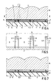
- Figure 4 is a cross-sectional view of part of an infrared detector in accordance with the present invention;
- Figure 5 is a plan view of one example of the detector-element and slotted-layer structure of Figure 4 for a linear array, and taken on the line V-V of Figure 4;
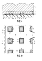
- Figure 6 is a plan view of one example of the detector-element and slotted-layer structure of Figure 4 for a 2-dimensional array, and taken on the line V-V of Figure 4;
- Figure 7 is a cross-sectional view similar to Figure 4 of part of the detector of Figure 5 in a modified form also in accordance with the present invention;
- Figure 8 is a plan view (similar to Figure 6) of one example of a lower-level layer of detector elements and slots on which the structure of Figure 6 may be provided to form a 2-level 2-dimensional array of detector elements with different wavelength response, between the substrate and optical element;
- Figure 9 is a cross-sectional view on the line XI-XI of Figure 10 of part of another example of an infrared detector array in accordance with the present invention and having a modified form for its detector elements, and
- Figure 10 is a plan view of the detector-element and slotted-layer structure of Figure 9.
- It should be noted that Figures 1 and 2 and Figures 4 to 10 are diagrammatic and not drawn to scale. Relative dimensions and proportions of part of these Figures have been shown exaggerated or reduced in size for the sake of clarity and convenience in the drawings. The same reference signs are generally used to refer to corresponding or similar features in the different embodiments and different drawings.
- The infrared detector of Figures 3 and 4 comprises an array of detector elements sandwiched between a
substrate 20 and alens plate 10. Each detector element comprises abody 1 of infrared-sensitive semiconductor material having an energy bandgap suitable for detecting infrared radiation up to a specified cut-off wavelength at the operating temperature of the detector. In operation, the detector elements are normally cooled by thermal conduction through thesubstrate 20 to a cryogenic cooler. Thus, for example, thebody 1 may be of cadmium mercury telluride whose composition is such that it has a cut-off wavelength of, for example about 12αrn at about 77K and about 9tim at about 192K. As is known, a temperature of about 77K can be obtained with a liquid-nitrogen cryostat (for example a Joule-Thomson cooler, or Stirling engine), whereas a temperature of 192K can be obtained thermoelectrically using a Peltier cooler. - In accordance with the present invention, each
element body 1 is a part of awider layer body 1 between thesubstrate 20 and thelens plate 10. There is present between thelayer lens plate 10 anadhesive film 11 by means of which thelens plate 10 is secured over theelement bodies 1. Eachelement body 1 is laterally separated around at least a majority of its periphery from theremainder 8 of thelayer slot 9. Theslot 9 extends through the thickness of thelayer 1 and 8 (see Figure 4) and defines at least a majority of the periphery of the element body 1 (see Figures 5 and 6). In the example of Figure 5, theslot 9 extends on three of the four sides of theelement body 1 as a U shaped outline around most of the body periphery. In the example of Figure 6, theslot 9 extends on all sides of theelement body 1 as a rectangular outline. - In specific examples of the detector of Figures 4 and 5 or Figures 4 and 6, each
element body 1 comprises a verticalp-n junction 3 between ann type region 4 at one end of thebody 1 anda p type region 2 at the opposite end of thebody 1. Thelayer electrode 6. A thin metal layer (for example of chromium) deposited to form theelectrode 6 may also provide theelectrode 5 for thep type region 2. The structure of the detector elements in this example is such that theslots 9 extend through the entire thickness of thelayer slot 9 may be etched through thelayer remainder 8 of thelayer - In this specific example of the detector of Figures 4 and 5, the
substrate 20 may be of, for example, sapphire or another insulating material carrying a metallisation pattern forming conductor tracks as electrical connections for the detector elements (similar totracks layer substrate 20 by anadhesive film 12, and is processed to form theregions 4, apertures 7,electrodes slots 9 in situ on thesubstrate 20. Theelectrode 6 of each detector element extends in the aperture 7 through the thickness of thebody 1 to an underlying part of the substrate connection 24 (which is only shown in Figure 5 where it crosses the slot 9). - In the embodiment of Figure 4, the adhesive film 11 (which may be an insulating epoxy, in a specific example) is present both in the
slots 9 and on eachelement body 1 facing thelens plate 10 so as to bond each detector element to theplate 10. The adhesive film between theelement body 1 and thelens plate 10 is very thin so that the detector elements are optically immersed on the lens. Even in this case with the adhesive 11 in theslots 9, the volume of the adhesive 11 contacting thebodies 1 is greatly reduced in the Figure 4 structure in accordance with the invention, as compared with the Figure 1 structure. This significantly reduces straining of the semiconductor lattice of the cadmiummercury telluride body 1 and its consequent change in the energy bandgap. - Table 1 illustrates this improvement, in terms of the cut-off wavelength X in µm measured at two temperatures (77K and 192K) both before and after bonding the
lens plate 10 to the detector-element bodies 1 by theadhesive film 11.
- The results of Table 1 were measured for three different detector element structures (DES) formed from the same slice of cadmium mercury telluride, each mounted on its
own sapphire substrate 20 below alens plate 10. Detector element structures 5a and 5b were those of the specific example of Figures 4 and 5, in which the thickness of the cadmiummercury telluride layer element bodies 1 were 10µm wide and 15µm long, theslots 9 were about sum wide, the width of thelayer part 8 between neighbouringelement bodies 1 was about 35µrn, and the epoxy adhesive film was 100 to 200nm thick on theelement bodies 1 and filled theslots 9. Detector element structures 2a to 2d were for a comparable specific example of Figures 1 and 2 having the same element body size as for DES 5a and 5b but with thelayer part 8 etched away and filled with theepoxy adhesive 11. Detector element structures 3a to 3c were for another comparable specific example in which thedetector elements 1 of Figures 1 and 2 and of Figures 4 and 5 were replaced with a p type layer of the same thickness as thelayer slots 9 in the layer. The spread in values for the same detector-element structures measured under the same conditions result from the measurement accuracy and slight variations in the thickness of the cadmium mercury telluride and the epoxy adhesive. - As can be seen from the "before" and "after" measurements in Table 1, there is little change in the cut-off wavelength for the DESs 5a and 5b in accordance with the invention. Furthermore, the "after" measurements of these DESs 5a and 5b are comparable with those for the virtually continuous layer of DESs 3a to 3c. By contrast the measurements of the DESs 2a to 2d show a decrease in X of about 1µm after bonding to the
lens plate 10, at both operating temperatures 77K and 192K. Although DESs 3a to 3c had comparable characteristics to DESs 5a and 5b in accordance with the invention, the detectivity (D*) of DESs 3a to 3c was only 0.7cm.Hz'.W-1 at 192K and this was only a third of the detectivity of DESs 5a and 5b at that temperature. This poorer performance of DESs 3a to 3c seems to result from the large volume of p type material around their element junctions which contributes to the thermally-generated leakage currents in DESs 3a to 3c. By contrast therewith, DESs 5a and 5b in accordance with the invention had a higher junction resistance which seems to result from theslots 9 extending on three of the four sides of the element body so restricting the volume of p type material which contributes to the thermally-generated leakage current of the detector element. - The following Table 2 lists similar measurements made on further detector element structures in accordance with the specific example of Figures 4 and 5 and with substantially the same dimensions, but constructed from different slices of cadmium mercury telluride of about the same composition.

- It is possible to confine the adhesive to the perimeter of the
layer adhesive film 11. Thus, in the linear array of Figure 5, the adhesive 11 may be provided in a rectangular frame around thelayer lens plate 10 tightly against thelayer detector elements 1 and thelens plate 10 so as to preserve good optical immersion. However, rather than trying to limit the location of theadhesive film 11 on thelayer slots 9 and tends to fill these slots, although they may remain partly unfilled due to trapped pockets of air. In order to reduce the volume of adhesive 11 bonding the element bodies (and so reduce stress in the element bodies 1), the width of theslots 9 is preferably kept to a minimum consistent with a reliable manufacturing yield. The minimum reliably reproduceable width for theslots 9 depends on the etching process used for their formation. However, typically, the width of theslots 9 may be between two and three times the thickness of thelayer layer - The detector elements shown in Figure 5 are arranged in a row as a linear array. The
remainder 8 of thelayer 1 does not comprise infrared detector elements of the array but merely forms a grid (in the shape of a ladder) which occupies a majority of the volume around the detector-element bodies 1 so as to reduce their straining by theadhesive film 11. In the particular form shown in Figure 5, the row ofbodies 1 extend laterally as fingers of a comb from an integral part of theremainder 8 of thelayer electrode 5 which forms a common electrical connection to the row ofelement bodies 1. The commonextended electrode 5 may electrically contact most (or even the whole) of the p type underlying integral part which may therefore form an electrical part of the common electrical connection of the array. However, except where it contacts theregion 2 in eachelement body 1, theextended electrode 5 may be insulated by a passivation layer of ZnS from the p type underlying integral part which may therefore simply constitute a mechanical support for part of the commonelectrical connection 5. The commonextended electrode 5 may extend over the edge of thelayer part 8 and onto the substrate conductor 22 (not shown in Figure 5). - However a modification of Figure 5 is possible in which the
slots 9 extend also on the fourth side of eachrectangular body 1 so as to isolate theelement bodies 1 from theremainder 8 of thelayer electrode 5 of each detector element may be confined to an end face of thep type region 2 of eachelement body 1 and extend directly from that end face to aconductor track 22 on thesubstrate 20. The body structure of each detector element may even be similar to that of theelement bodies 1 of Figure 2, except that theremainder 8 of thelayer element bodies 1 extends as a grid between and around theelement bodies 1 from which it is separated by theslots 9. - Figure 5 illustrates a single row of the
element bodies 1 arranged in a linear array. The structure of Figure 5 can be adapted to form two such rows ofelement bodies 1 by providing a mirror image of the Figure 5 structure at the top half of Figure 5. In this double-row device, theelement bodies 1 of one row may be located in line withcorresponding element bodies 1 of the other row. Alternatively, theelement bodies 1 of one row may be located in line withlayer parts 8 between neighbouringelement bodies 1 of the other row. - The present invention may also be used for 2-dimensional arrays of detector elements. One example of such a 2-dimensional array in accordance with the invention is illustrated in Figure 6, in which the
element bodies 1 are isolated parts of thelayer remainder 8 of which does not comprise any infrared detector elements and forms a rectangular grid network around theelement bodies 1 from which it is separated by theslots 9. Theelectrodes 5 to thep type region 2 of each detector element may extend on an end face of theelement body 1. Theelectrodes 6 to then type regions 4 may extend on an opposite end face of eachbody 1 or in a aperture 7 in eachelement body 1. It is also possible to use thegrid 8 to support (or even form an electrical part of) a common connection to thep type regions 2 of the detector elements by having theslot 9 on three sides only (i.e. not at the p type end) of eachelement body 1. In the Figure 6 embodiment an insulatingsubstrate 20 with conductor tracks 24 and 25 may be used (similar to the previous embodiments). Alternatively, thesubstrate 20 may be, for example, a silicon integrated circuit comprising both connections for the detector elements and circuitry for processing the signals from the detector elements. - In the embodiments so far described, the
lens plate 10 is bonded by theadhesive film 11 to thelayer substrate 20. Figure 7 illustrates another embodiment in which thelayer lens plate 10, and thesubstrate 20 is then bonded by theadhesive film 11 to thelayer lens plate 10. In this case, thelayer lens plate 10 which may be of for example monocrystalline cadmium telluride or for example monocrystalline silicon coated with cadmium telluride at the face where the cadmiummercury telluride layer lens plate 10, it is then processed to form theregions 4, apertures 7,electrodes slots 9 in situ on thelens plate 20. In this case, the detector elements may be connected to circuitry formed in parts of the silicon lens plate adjacent to thepart 8 of the cadmiummercury telluride layer - The embodiments illustrated herein have been described with a
layer - Although an array of lenses corresponding to the array of detector elements has been illustrated in a
lens plate 10, the invention may also be used with other optical elements. Thus, theelement bodies 1 and theremainder 8 of thelayer 1 and 8 (with the slots 9) may be sandwiched between asubstrate 20 and anoptical plate 10 comprising an array of prismatic elements corresponding to the array of detector-elements (for example as in GB-A-1 525 562), or even a wedge-shaped plate or single lens element over the whole of an array (for example as in Figures 2,5,8 and 9 of United Kingdom patent application 8531497.9 published as GB-A-2 240 444 on 31st July 1991). The whole contents of GB-A-2 240 444 (our reference PHB33234) are hereby incorporated herein as reference material. - Furthermore, although the embodiments described so far show only a single level of detector elements between the
substrate 20 and theoptical element 10, the invention may be applied to each level of a multiple-level detector array structure (for example as described in pending United Kingdom patent application 9022464.3, our reference PHB33674, filed on 17th October 1990 and published as GB-A-2 248 964 on 22nd April 1992). The whole contents of GB-A-2 248 964 are hereby incorporated herein as reference material. The two levels may comprise different infrared-sensitive semiconductor materials having different bandgaps so as to provide different infrared wavelength responses. The lower level may be mounted on, for example, a silicon integratedcircuit 20 via an epoxy adhesive layer. As an example in accordance with the invention, the upper level of detector elements may have thelayer structure layer structure slots 9 not only separate thelower element bodies 1 from the remainder of thelayer 8 but also isolate bothn type islands 84 andp type islands 85 from thep type remainder 8 of the layer and from thelower element bodies 1. When the upperlevel layer structure element bodies 1 are superimposed as a cross centred on the symbol +' in Figures 6 and 7 and then type region 4 of the upper detector elements overlies a lowern type island 84. The aperture 7 through theupper region 4 is continued through the underlyingisland 84 as anaperture 87 to carry the upper-level electrode 6 to thecircuit substrate 20. The upper-level electrode 5 may be carried to thecircuit substrate 20 via thep type islands 85. Theupper layer lower layer optical element 10 is bonded to theupper layer film 11 as previously described. - Even in a device embodiment having a single level of
detector elements 1 in a single slottedlayer substrate 20 and theoptical element 10, theslots 9 in thelayer islands element bodies 1 and theremainder 8 of thelayer detector elements 1 of thelayer electrodes element body 1 or through an aperture 7 in theelement body 1, the detector element connections may comprise theislands element body 1 by bridging conductor tracks extending over an insulating filling in theslots 9. - The detector elements in the embodiments of Figures 4 to 8 comprise a vertical
p-n junction 3, and theslots 9 extend through the entire thickness of thelayer element body 1. The embodiment of Figures 9 and 10 illustrates a modified detector-element structure having a horizontalp-n junction 3 between ann type region 4 and an underlyingp type region 2. Thetotal semiconductor layer a p type sub-layer 2 adjacent one face and n type regions adjacent its opposite face. Theslots 9 are present in this opposite face and extend through only a part of the thickness of thelayer n type sub-layer 2. In a specific example, the total thickness of thelayer slots 9 may have a depth of 6µrn. - The
p type sub-layer 2 provides a common electrical connection of the array of detector elements, and it may extend to the opposite face (for example at a peripheral region of thelayer 1 and 8) where anelectrode 5 may be provided. The n type regions adjacent this opposite face may be restricted to the areas of theelement bodies 1, or they may be present also in theremainder 8 of the layer in which case (as shown in Figures 9 and 10) they are isolated from theelement regions 4 by theslots 9. Theelement bodies 1 haveindividual electrodes 6 contacting theirregions 4. Figure 10 illustrates this embodiment as a modification of the Figure 7 arrangement in which thelayer lens plate 10. - In the embodiments of Figures 4 to 10, one or more slotted infrared-
sensitive semiconductor layers substrate 20 andoptical element 10. However, the detector elements may comprise a slottedlayer substrate 20 and theoptical element 10. - From reading the present disclosure, other variations and modifications will be apparent to persons skilled in the art. Such variations and modifications may involve equivalents and other features which are already known in the design, manufacture and use of infrared detectors and component parts thereof, and which may be used instead of or in addition to features already described herein. Although claims have been formulated in this application to particular combinations of features, it should be understood that the scope of the disclosure of the present application also includes any novel feature or any novel combination of features disclosed herein either explicitly or implicitly or any generalisation thereof, whether or not it relates to the same invention as presently claimed in any claim and whether or not it mitigates any or all of the same technical problems as does the present invention. The applicants hereby give notice that new claims may be formulated to such features and/or combinations of such features during the prosecution of the present application or of any further application derived therefrom.
Claims (11)
Applications Claiming Priority (2)
| Application Number | Priority Date | Filing Date | Title |
|---|---|---|---|
| GB919116307A GB9116307D0 (en) | 1991-07-29 | 1991-07-29 | Infrared detectors |
| GB9116307 | 1991-07-29 |
Publications (2)
| Publication Number | Publication Date |
|---|---|
| EP0525876A1 true EP0525876A1 (en) | 1993-02-03 |
| EP0525876B1 EP0525876B1 (en) | 1996-05-08 |
Family
ID=10699140
Family Applications (1)
| Application Number | Title | Priority Date | Filing Date |
|---|---|---|---|
| EP92202222A Expired - Lifetime EP0525876B1 (en) | 1991-07-29 | 1992-07-20 | Infrared detectors |
Country Status (4)
| Country | Link |
|---|---|
| US (1) | US5306915A (en) |
| EP (1) | EP0525876B1 (en) |
| DE (1) | DE69210497T2 (en) |
| GB (1) | GB9116307D0 (en) |
Cited By (14)
| Publication number | Priority date | Publication date | Assignee | Title |
|---|---|---|---|---|
| DE19641272A1 (en) * | 1996-10-07 | 1998-04-09 | Franz Heinz Guenther | Optoelectronic hybrid components mfg. method for sensor |
| DE10222960A1 (en) * | 2002-05-23 | 2003-12-11 | Schott Glas | Making electronic component comprising semiconductor elements with device for sensing or emitting |
| WO2004023564A2 (en) * | 2002-09-09 | 2004-03-18 | Koninklijke Philips Electronics N.V. | Optoelectronic semiconductor device and method of manufacturing such a device |
| DE19627543B4 (en) * | 1996-05-18 | 2004-05-06 | Thomas Hofmann | Multi-layer substrate and method for its production |
| FR2869462A1 (en) * | 2004-04-21 | 2005-10-28 | Fr De Detecteurs Infrarouges S | Infrared radiation detector fabricating process for e.g. electronic readout circuit, involves subjecting stack consisting of common base and passivation layers to thermal annealing under mercury vapor after forming openings in one layer |
| DE19816309B4 (en) * | 1997-04-14 | 2008-04-03 | CiS Institut für Mikrosensorik gGmbH | Method for direct mounting of silicon sensors and sensors manufactured thereafter |
| US9635727B2 (en) | 2008-10-24 | 2017-04-25 | Ilumisys, Inc. | Light and light sensor |
| US9777893B2 (en) | 2000-02-11 | 2017-10-03 | Ilumisys, Inc. | Light tube and power supply circuit |
| US9807842B2 (en) | 2012-07-09 | 2017-10-31 | Ilumisys, Inc. | System and method for controlling operation of an LED-based light |
| US10571115B2 (en) | 2008-10-24 | 2020-02-25 | Ilumisys, Inc. | Lighting including integral communication apparatus |
| US10690296B2 (en) | 2015-06-01 | 2020-06-23 | Ilumisys, Inc. | LED-based light with canted outer walls |
| US10713915B2 (en) | 2008-10-24 | 2020-07-14 | Ilumisys, Inc. | Integration of LED lighting control with emergency notification systems |
| CN112057745A (en) * | 2019-06-11 | 2020-12-11 | 乐金显示有限公司 | Electronic device for skin management or skin treatment |
| US10973094B2 (en) | 2008-10-24 | 2021-04-06 | Ilumisys, Inc. | Integration of LED lighting with building controls |
Families Citing this family (38)
| Publication number | Priority date | Publication date | Assignee | Title |
|---|---|---|---|---|
| JP2833450B2 (en) * | 1993-11-24 | 1998-12-09 | 日本電気株式会社 | Infrared imaging device |
| US5593902A (en) * | 1994-05-23 | 1997-01-14 | Texas Instruments Incorporated | Method of making photodiodes for low dark current operation having geometric enhancement |
| US5828068A (en) * | 1996-04-04 | 1998-10-27 | Raytheon Ti Systems, Inc. | Uncooled mercury cadmium telluride infrared devices with integral optical elements |
| IL128450A (en) * | 1999-02-09 | 2002-05-23 | Elop Electrooptics Ind Ltd | Method of bonding an optical element within an enclosure |
| US7485799B2 (en) * | 2002-05-07 | 2009-02-03 | John Michael Guerra | Stress-induced bandgap-shifted semiconductor photoelectrolytic/photocatalytic/photovoltaic surface and method for making same |
| US20080283121A1 (en) * | 2002-05-07 | 2008-11-20 | Nanoptek Corporation | Bandgap-shifted semiconductor surface and method for making same, and apparatus for using same |
| US7995871B2 (en) * | 2002-05-07 | 2011-08-09 | Nanoptek Corporation | Stress-induced bandgap-shifted semiconductor photoelectrolytic/photocatalytic/photovoltaic surface and method for making same |
| US8673399B2 (en) * | 2002-05-07 | 2014-03-18 | Nanoptek Corporation | Bandgap-shifted semiconductor surface and method for making same, and apparatus for using same |
| JP2003344548A (en) * | 2002-05-24 | 2003-12-03 | Seiko Instruments Inc | Radiation detector |
| US8118447B2 (en) | 2007-12-20 | 2012-02-21 | Altair Engineering, Inc. | LED lighting apparatus with swivel connection |
| US7712918B2 (en) | 2007-12-21 | 2010-05-11 | Altair Engineering , Inc. | Light distribution using a light emitting diode assembly |
| US8360599B2 (en) | 2008-05-23 | 2013-01-29 | Ilumisys, Inc. | Electric shock resistant L.E.D. based light |
| US7976196B2 (en) | 2008-07-09 | 2011-07-12 | Altair Engineering, Inc. | Method of forming LED-based light and resulting LED-based light |
| US7946729B2 (en) | 2008-07-31 | 2011-05-24 | Altair Engineering, Inc. | Fluorescent tube replacement having longitudinally oriented LEDs |
| US8674626B2 (en) | 2008-09-02 | 2014-03-18 | Ilumisys, Inc. | LED lamp failure alerting system |
| US8256924B2 (en) | 2008-09-15 | 2012-09-04 | Ilumisys, Inc. | LED-based light having rapidly oscillating LEDs |
| US8444292B2 (en) | 2008-10-24 | 2013-05-21 | Ilumisys, Inc. | End cap substitute for LED-based tube replacement light |
| US8324817B2 (en) | 2008-10-24 | 2012-12-04 | Ilumisys, Inc. | Light and light sensor |
| US8556452B2 (en) | 2009-01-15 | 2013-10-15 | Ilumisys, Inc. | LED lens |
| US8362710B2 (en) | 2009-01-21 | 2013-01-29 | Ilumisys, Inc. | Direct AC-to-DC converter for passive component minimization and universal operation of LED arrays |
| US8664880B2 (en) | 2009-01-21 | 2014-03-04 | Ilumisys, Inc. | Ballast/line detection circuit for fluorescent replacement lamps |
| US8330381B2 (en) | 2009-05-14 | 2012-12-11 | Ilumisys, Inc. | Electronic circuit for DC conversion of fluorescent lighting ballast |
| US8299695B2 (en) | 2009-06-02 | 2012-10-30 | Ilumisys, Inc. | Screw-in LED bulb comprising a base having outwardly projecting nodes |
| WO2011005579A2 (en) | 2009-06-23 | 2011-01-13 | Altair Engineering, Inc. | Illumination device including leds and a switching power control system |
| CA2792940A1 (en) | 2010-03-26 | 2011-09-19 | Ilumisys, Inc. | Led light with thermoelectric generator |
| CA2794512A1 (en) | 2010-03-26 | 2011-09-29 | David L. Simon | Led light tube with dual sided light distribution |
| US8540401B2 (en) | 2010-03-26 | 2013-09-24 | Ilumisys, Inc. | LED bulb with internal heat dissipating structures |
| US8454193B2 (en) | 2010-07-08 | 2013-06-04 | Ilumisys, Inc. | Independent modules for LED fluorescent light tube replacement |
| JP2013531350A (en) | 2010-07-12 | 2013-08-01 | イルミシス,インコーポレイテッド | Circuit board mount for LED arc tube |
| US8523394B2 (en) | 2010-10-29 | 2013-09-03 | Ilumisys, Inc. | Mechanisms for reducing risk of shock during installation of light tube |
| US8870415B2 (en) | 2010-12-09 | 2014-10-28 | Ilumisys, Inc. | LED fluorescent tube replacement light with reduced shock hazard |
| US9072171B2 (en) | 2011-08-24 | 2015-06-30 | Ilumisys, Inc. | Circuit board mount for LED light |
| US9184518B2 (en) | 2012-03-02 | 2015-11-10 | Ilumisys, Inc. | Electrical connector header for an LED-based light |
| US9163794B2 (en) | 2012-07-06 | 2015-10-20 | Ilumisys, Inc. | Power supply assembly for LED-based light tube |
| US9285084B2 (en) | 2013-03-14 | 2016-03-15 | Ilumisys, Inc. | Diffusers for LED-based lights |
| US9267650B2 (en) | 2013-10-09 | 2016-02-23 | Ilumisys, Inc. | Lens for an LED-based light |
| CN106063381A (en) | 2014-01-22 | 2016-10-26 | 伊卢米斯公司 | LED-based light with addressed LEDs |
| US9510400B2 (en) | 2014-05-13 | 2016-11-29 | Ilumisys, Inc. | User input systems for an LED-based light |
Citations (4)
| Publication number | Priority date | Publication date | Assignee | Title |
|---|---|---|---|---|
| US4352948A (en) * | 1979-09-07 | 1982-10-05 | Massachusetts Institute Of Technology | High-intensity solid-state solar-cell device |
| GB2132757A (en) * | 1982-12-22 | 1984-07-11 | Secr Defence | Infra-red detector assembly |
| GB2138209A (en) * | 1983-04-08 | 1984-10-17 | Telecommunications Sa | Photoconducting detector in optical immersion |
| GB2241605A (en) * | 1985-09-11 | 1991-09-04 | Philips Electronic Associated | Infrared photodiodes, arrays and their manufacture |
Family Cites Families (7)
| Publication number | Priority date | Publication date | Assignee | Title |
|---|---|---|---|---|
| GB1525562A (en) * | 1975-08-19 | 1978-09-20 | Hawker Siddeley Aviation Ltd | Multi-element targets sensitive to incident radiation |
| GB2095905B (en) * | 1981-03-27 | 1985-01-16 | Philips Electronic Associated | Infra-red radiation imaging devices and methods for their manufacture |
| US4559695A (en) * | 1981-03-27 | 1985-12-24 | U.S. Philips Corporation | Method of manufacturing an infrared radiation imaging device |
| JPS61182531A (en) * | 1985-02-08 | 1986-08-15 | Matsushita Electric Ind Co Ltd | Two-dimensional array infrared detector |
| GB2240444B (en) * | 1985-12-20 | 1991-10-30 | Philips Electronic Associated | Imaging array devices and staring array imaging systems |
| JPH01320438A (en) * | 1988-06-22 | 1989-12-26 | Fujitsu Ltd | Infrared detector |
| GB2248964A (en) * | 1990-10-17 | 1992-04-22 | Philips Electronic Associated | Plural-wavelength infrared detector devices |
-
1991
- 1991-07-29 GB GB919116307A patent/GB9116307D0/en active Pending
-
1992
- 1992-07-20 EP EP92202222A patent/EP0525876B1/en not_active Expired - Lifetime
- 1992-07-20 DE DE69210497T patent/DE69210497T2/en not_active Expired - Fee Related
- 1992-07-28 US US07/922,117 patent/US5306915A/en not_active Expired - Fee Related
Patent Citations (4)
| Publication number | Priority date | Publication date | Assignee | Title |
|---|---|---|---|---|
| US4352948A (en) * | 1979-09-07 | 1982-10-05 | Massachusetts Institute Of Technology | High-intensity solid-state solar-cell device |
| GB2132757A (en) * | 1982-12-22 | 1984-07-11 | Secr Defence | Infra-red detector assembly |
| GB2138209A (en) * | 1983-04-08 | 1984-10-17 | Telecommunications Sa | Photoconducting detector in optical immersion |
| GB2241605A (en) * | 1985-09-11 | 1991-09-04 | Philips Electronic Associated | Infrared photodiodes, arrays and their manufacture |
Cited By (27)
| Publication number | Priority date | Publication date | Assignee | Title |
|---|---|---|---|---|
| DE19627543B4 (en) * | 1996-05-18 | 2004-05-06 | Thomas Hofmann | Multi-layer substrate and method for its production |
| DE19627543B9 (en) * | 1996-05-18 | 2004-10-14 | Thomas Hofmann | Multi-layer substrate and method for its production |
| DE19641272A1 (en) * | 1996-10-07 | 1998-04-09 | Franz Heinz Guenther | Optoelectronic hybrid components mfg. method for sensor |
| DE19641272C2 (en) * | 1996-10-07 | 2003-03-27 | Franz Heinz Guenther | Process for producing opto-electronic hybrid components with screens |
| DE19816309B4 (en) * | 1997-04-14 | 2008-04-03 | CiS Institut für Mikrosensorik gGmbH | Method for direct mounting of silicon sensors and sensors manufactured thereafter |
| US10557593B2 (en) | 2000-02-11 | 2020-02-11 | Ilumisys, Inc. | Light tube and power supply circuit |
| US9777893B2 (en) | 2000-02-11 | 2017-10-03 | Ilumisys, Inc. | Light tube and power supply circuit |
| DE10222960A1 (en) * | 2002-05-23 | 2003-12-11 | Schott Glas | Making electronic component comprising semiconductor elements with device for sensing or emitting |
| WO2004023564A2 (en) * | 2002-09-09 | 2004-03-18 | Koninklijke Philips Electronics N.V. | Optoelectronic semiconductor device and method of manufacturing such a device |
| WO2004023564A3 (en) * | 2002-09-09 | 2005-01-13 | Koninkl Philips Electronics Nv | Optoelectronic semiconductor device and method of manufacturing such a device |
| US7351951B2 (en) | 2002-09-09 | 2008-04-01 | Koninklijke Philips Electronics N.V. | Optoelectronic semiconductor device and method of manufacturing such a device |
| FR2869462A1 (en) * | 2004-04-21 | 2005-10-28 | Fr De Detecteurs Infrarouges S | Infrared radiation detector fabricating process for e.g. electronic readout circuit, involves subjecting stack consisting of common base and passivation layers to thermal annealing under mercury vapor after forming openings in one layer |
| US9635727B2 (en) | 2008-10-24 | 2017-04-25 | Ilumisys, Inc. | Light and light sensor |
| US10973094B2 (en) | 2008-10-24 | 2021-04-06 | Ilumisys, Inc. | Integration of LED lighting with building controls |
| US10560992B2 (en) | 2008-10-24 | 2020-02-11 | Ilumisys, Inc. | Light and light sensor |
| US10571115B2 (en) | 2008-10-24 | 2020-02-25 | Ilumisys, Inc. | Lighting including integral communication apparatus |
| US11333308B2 (en) | 2008-10-24 | 2022-05-17 | Ilumisys, Inc. | Light and light sensor |
| US10713915B2 (en) | 2008-10-24 | 2020-07-14 | Ilumisys, Inc. | Integration of LED lighting control with emergency notification systems |
| US11073275B2 (en) | 2008-10-24 | 2021-07-27 | Ilumisys, Inc. | Lighting including integral communication apparatus |
| US10932339B2 (en) | 2008-10-24 | 2021-02-23 | Ilumisys, Inc. | Light and light sensor |
| US9807842B2 (en) | 2012-07-09 | 2017-10-31 | Ilumisys, Inc. | System and method for controlling operation of an LED-based light |
| US10966295B2 (en) | 2012-07-09 | 2021-03-30 | Ilumisys, Inc. | System and method for controlling operation of an LED-based light |
| US11028972B2 (en) | 2015-06-01 | 2021-06-08 | Ilumisys, Inc. | LED-based light with canted outer walls |
| US10690296B2 (en) | 2015-06-01 | 2020-06-23 | Ilumisys, Inc. | LED-based light with canted outer walls |
| US11428370B2 (en) | 2015-06-01 | 2022-08-30 | Ilumisys, Inc. | LED-based light with canted outer walls |
| CN112057745A (en) * | 2019-06-11 | 2020-12-11 | 乐金显示有限公司 | Electronic device for skin management or skin treatment |
| CN112057745B (en) * | 2019-06-11 | 2023-06-23 | 乐金显示有限公司 | Electronic device for skin management or skin treatment |
Also Published As
| Publication number | Publication date |
|---|---|
| DE69210497T2 (en) | 1996-09-05 |
| EP0525876B1 (en) | 1996-05-08 |
| US5306915A (en) | 1994-04-26 |
| DE69210497D1 (en) | 1996-06-13 |
| GB9116307D0 (en) | 1991-11-06 |
Similar Documents
| Publication | Publication Date | Title |
|---|---|---|
| EP0525876B1 (en) | Infrared detectors | |
| EP0475525B1 (en) | Plural-wavelength infrared detector devices | |
| US6111254A (en) | Infrared radiation detector | |
| US6355939B1 (en) | Multi-band infrared photodetector | |
| CA2220834C (en) | Enhanced quantum well infrared photodetector | |
| US4783594A (en) | Reticular detector array | |
| EP0481552B1 (en) | Infrared detector devices | |
| EP0864171B1 (en) | Forming contacts on semiconductor substrates for radiation detectors and imaging devices | |
| US4972244A (en) | Photodiode and photodiode array on a II-VI material and processes for the production thereof | |
| EP0087842B1 (en) | Infra-red radiation detectors and their manufacture | |
| US5264699A (en) | Infrared detector hybrid array with improved thermal cycle reliability and method for making same | |
| US5721429A (en) | Self-focusing detector pixel structure having improved sensitivity | |
| US5401986A (en) | Bake-stable HgCdTe photodetector with II-VI passivation layer | |
| US4422091A (en) | Backside illuminated imaging charge coupled device | |
| US5064771A (en) | Method of forming crystal array | |
| US5751049A (en) | Two-color infrared detector | |
| US5296384A (en) | Bake-stable HgCdTe photodetector and method for fabricating same | |
| GB2241605A (en) | Infrared photodiodes, arrays and their manufacture | |
| US5517029A (en) | Dual-band IR scanning focal plane assembly having two monolithically integrated linear detector arrays for simultaneous image readout | |
| US4801802A (en) | Imaging, device, elements and systems | |
| GB2206447A (en) | Lensed photodetector | |
| CA1088190A (en) | Integrated photoelectrical conversion | |
| JP2705594B2 (en) | Infrared detector | |
| EP0248881A1 (en) | Structure and method of fabricating a trapping-mode photodetector | |
| JPS6322471B2 (en) |
Legal Events
| Date | Code | Title | Description |
|---|---|---|---|
| PUAI | Public reference made under article 153(3) epc to a published international application that has entered the european phase |
Free format text: ORIGINAL CODE: 0009012 |
|
| AK | Designated contracting states |
Kind code of ref document: A1 Designated state(s): DE FR GB |
|
| 17P | Request for examination filed |
Effective date: 19930713 |
|
| R17P | Request for examination filed (corrected) |
Effective date: 19930719 |
|
| RAP1 | Party data changed (applicant data changed or rights of an application transferred) |
Owner name: GEC-MARCONI LIMITED |
|
| 17Q | First examination report despatched |
Effective date: 19950727 |
|
| GRAH | Despatch of communication of intention to grant a patent |
Free format text: ORIGINAL CODE: EPIDOS IGRA |
|
| GRAA | (expected) grant |
Free format text: ORIGINAL CODE: 0009210 |
|
| AK | Designated contracting states |
Kind code of ref document: B1 Designated state(s): DE FR GB |
|
| REF | Corresponds to: |
Ref document number: 69210497 Country of ref document: DE Date of ref document: 19960613 |
|
| ET | Fr: translation filed | ||
| PLBE | No opposition filed within time limit |
Free format text: ORIGINAL CODE: 0009261 |
|
| STAA | Information on the status of an ep patent application or granted ep patent |
Free format text: STATUS: NO OPPOSITION FILED WITHIN TIME LIMIT |
|
| 26N | No opposition filed | ||
| PGFP | Annual fee paid to national office [announced via postgrant information from national office to epo] |
Ref country code: FR Payment date: 19980611 Year of fee payment: 7 |
|
| PGFP | Annual fee paid to national office [announced via postgrant information from national office to epo] |
Ref country code: GB Payment date: 19980626 Year of fee payment: 7 |
|
| PGFP | Annual fee paid to national office [announced via postgrant information from national office to epo] |
Ref country code: DE Payment date: 19980629 Year of fee payment: 7 |
|
| PG25 | Lapsed in a contracting state [announced via postgrant information from national office to epo] |
Ref country code: GB Free format text: LAPSE BECAUSE OF NON-PAYMENT OF DUE FEES Effective date: 19990720 |
|
| PG25 | Lapsed in a contracting state [announced via postgrant information from national office to epo] |
Ref country code: FR Free format text: THE PATENT HAS BEEN ANNULLED BY A DECISION OF A NATIONAL AUTHORITY Effective date: 19990731 |
|
| GBPC | Gb: european patent ceased through non-payment of renewal fee |
Effective date: 19990720 |
|
| PG25 | Lapsed in a contracting state [announced via postgrant information from national office to epo] |
Ref country code: DE Free format text: LAPSE BECAUSE OF NON-PAYMENT OF DUE FEES Effective date: 20000503 |
|
| REG | Reference to a national code |
Ref country code: FR Ref legal event code: ST |