EP0525247A1 - Vorrichtung zum Greifen eines Bohrlochrohrkörpers zum Zwecke des Drehens - Google Patents
Vorrichtung zum Greifen eines Bohrlochrohrkörpers zum Zwecke des Drehens Download PDFInfo
- Publication number
- EP0525247A1 EP0525247A1 EP91112981A EP91112981A EP0525247A1 EP 0525247 A1 EP0525247 A1 EP 0525247A1 EP 91112981 A EP91112981 A EP 91112981A EP 91112981 A EP91112981 A EP 91112981A EP 0525247 A1 EP0525247 A1 EP 0525247A1
- Authority
- EP
- European Patent Office
- Prior art keywords
- tubular
- down hole
- guides
- support member
- hole tubular
- Prior art date
- Legal status (The legal status is an assumption and is not a legal conclusion. Google has not performed a legal analysis and makes no representation as to the accuracy of the status listed.)
- Withdrawn
Links
- 238000005553 drilling Methods 0.000 claims abstract description 18
- 239000012530 fluid Substances 0.000 claims 1
- 241000282472 Canis lupus familiaris Species 0.000 abstract description 4
- 210000005069 ears Anatomy 0.000 description 5
- 230000007246 mechanism Effects 0.000 description 3
- 229910001369 Brass Inorganic materials 0.000 description 2
- 239000010951 brass Substances 0.000 description 2
- 238000010276 construction Methods 0.000 description 1
- 239000000463 material Substances 0.000 description 1
- 238000012986 modification Methods 0.000 description 1
- 230000004048 modification Effects 0.000 description 1
- 239000003129 oil well Substances 0.000 description 1
- 238000007789 sealing Methods 0.000 description 1
- 238000003466 welding Methods 0.000 description 1
Images


Classifications
-
- E—FIXED CONSTRUCTIONS
- E21—EARTH OR ROCK DRILLING; MINING
- E21B—EARTH OR ROCK DRILLING; OBTAINING OIL, GAS, WATER, SOLUBLE OR MELTABLE MATERIALS OR A SLURRY OF MINERALS FROM WELLS
- E21B19/00—Handling rods, casings, tubes or the like outside the borehole, e.g. in the derrick; Apparatus for feeding the rods or cables
- E21B19/02—Rod or cable suspensions
- E21B19/06—Elevators, i.e. rod- or tube-gripping devices
- E21B19/07—Slip-type elevators
-
- E—FIXED CONSTRUCTIONS
- E21—EARTH OR ROCK DRILLING; MINING
- E21B—EARTH OR ROCK DRILLING; OBTAINING OIL, GAS, WATER, SOLUBLE OR MELTABLE MATERIALS OR A SLURRY OF MINERALS FROM WELLS
- E21B19/00—Handling rods, casings, tubes or the like outside the borehole, e.g. in the derrick; Apparatus for feeding the rods or cables
- E21B19/16—Connecting or disconnecting pipe couplings or joints
-
- E—FIXED CONSTRUCTIONS
- E21—EARTH OR ROCK DRILLING; MINING
- E21B—EARTH OR ROCK DRILLING; OBTAINING OIL, GAS, WATER, SOLUBLE OR MELTABLE MATERIALS OR A SLURRY OF MINERALS FROM WELLS
- E21B3/00—Rotary drilling
- E21B3/02—Surface drives for rotary drilling
Definitions
- This invention relates to an improved apparatus for gripping a down hole tubular for rotation that it is suitable for use in a drilling machine, such as an oil well drilling machine, and that operates simply and reliably, with a minimum of parts.
- the apparatus can be designed either to fit around the upper end of the tubular as described in U.S. Patent Application Serial No. 07/107,286, assigned to the assignee of the present invention.
- the engaging apparatus can be designed to fit into the upper end of the down hole tubular and to grip the tubular from within, as described in U.S. Patent 4,762,187, also assigned to the assignee of the present invention.
- Both of these devices utilize friction brakes to move the clamping jaws into and out of engagement with the down hole tubular.
- this approach has been found effective and reliable, it is not without disadvantages.
- the braking mechanisms result in relatively complex linkages with a relatively large number of parts. There can be a concern among some users that parts may become disengaged from the mechanism and fall into the borehole, thereby creating significant problems.
- the device itself moves axially with respect to the remaining portions of the drilling machine. Such axial movement may complicate the braking mechanism used to engage and disengage the clamping elements from the down hole tubular.
- the present invention is directed to improved devices for engaging a down hole tubular for rotation, which to a large extent overcome the disadvantages discussed above by completely eliminating the need for a friction brake system.
- an apparatus for engaging a down hole tubular for rotation in a drilling machine of the type comprising a rotatable quill, means for rotating the quill, means for vertically positioning the quill, and means for vertically moving an additional element beneath the rotating means with respect to the quill.
- the tubular engaging apparatus of this invention comprises a support member adapted for connection to the quill.
- a plurality of guides are mounted on the support member around an axis defined by the support member, and these guides are disposed at an angle with respect to the axis.
- a plurality of engaging members are each mounted to move in a respective one of the guides to move into engagement with a down hole tubular when positioned toward a first end of the respective guide and to move out of engagement with a down hole tubular when positioned toward a second end of the respective guide.
- the engaging members are adapted to transmit torque from the guides to the engaged down hole tubular.
- a linkage is coupled to the engaging members and comprises an actuating member exposed at an upper portion of the support member and adapted for movement along the axis between a closed position, in which the linkage urges the engaging members toward the first ends of the guides, and an open position, in which the linkage urges the engaging members toward the second ends of the guides.
- This actuating member is adapted to bear against the additional element of the drilling machine, such that vertical movement of the additional element with respect to the quill moves the actuating member along the axis and therefore the engaging elements along the guides.
- the tubular engaging apparatus of this invention can be configured to engage the upper end of the tubular at either the internal or external surface of the tubular. Furthermore, the apparatus of this invention provides an extremely simple, reliable and rugged system which minimizes the number of parts and therefore the possibility that parts may become disengaged.
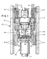
- FIG.1 shows portions of an earth drilling machine 10 which includes a top head drive assembly 12 that moves along a mast 13.
- the top head assembly 12 includes a main load beam 14 which is suspended from cables 16.
- the load beam 14 is attached to side frames that include guide wheels 18 that guide the top head drive assembly 12 for vertical movement along the mast 13.
- a rotating means 20 is mounted on top of the load beam 14, and serves to rotate a quill 22.
- the rotating means 20 can for example include hydraulic or electric motors and the quill 22 can be coupled to down hole tubulars, such as drill pipes or casing.
- a wrench assembly 24 is mounted beneath the load beam 14 so as to move vertically on guides 26 suspended from the load beam 14.
- a pair of hydraulic cylinders 28 are interposed between the wrench assembly 24 and the load beam 14 to control the vertical position of the wrench assembly 24.
- the wrench assembly 24 includes two vertically off-set wrenches which can be rotated with respect to one another in order to make-up and break-out threaded connections.
- FIGS.2 through 2c relate to a first preferred embodiment 30 of this invention and FIGS.3 and 3a relate to a second preferred embodiment 130.
- the tubular engaging apparatus 30 includes a support member 32 adapted for threaded connection to the quill 22.
- This support member 32 defines a central longitudinal axis 34, and it includes a stem 36, a flange 38 and body 40 that are welded together to form a single rigid unit.
- the stem 36 defines an upwardly facing shoulder 37 that supports the flange 38, and a passageway 42 extends completely through the stem 36 and serves to interconnect the central passageway of the quill 22 with the interior of the tubular T that is engaged in the apparatus 30.
- the body 40 supports three axially oriented guides 44, each of which converges downwardly toward the axis 34.
- Each of the guides 44 is mounted fixedly in place to the body 40 by fasteners 46 and defines a T-shaped slot 48.
- a clamping dog or engaging member 50 is mounted to slide in each of the T-shaped slots 48.
- Each of the clamping dogs 50 includes a toothed cylindrical face 52, as best shown in FIG.2b, which is shaped and configured to grip the exterior surface of the tubular T for rotation.
- the upper portion of each of the engaging members 50 defines a pair of ears 54.
- a lower link 56 extends between the ears 54 and an upper link 58 and the ears 54 and links 56, 58 are connected together by respective pivots 60.
- the upper ends of the upper links 58 are fixedly mounted, as for example by welding, to an annular actuating member 62 that extends parallel to the flange 38 around the stem 36.
- the actuating member 62 When mounted in place on the drilling machine 10, the actuating member 62 bears on a bearing element 64 that is mounted to the underside of the wrench assembly 24 by means of a thrust bearing 66.
- a latch assembly 70 that includes a sleeve 72 and a latch member 73.
- the sleeve 72 is horizontally oriented and fixed in place with respect to the wrench assembly 24 and the latch member 73 is free to slide horizontally in the sleeve 72.
- the latch member 73 is preferably made of brass or some other suitable bearing material and can be locked in either an extended or retracted position by a removable pin 74. When the latch member 73 is locked in the extended position, as shown on the right hand side of FIG.2, the latch member 73 holds the actuating member 62 in contact with the bearing element 64.
- the latch assembly 70 is shown in perspective view in FIG.2c and is designed to accommodate low speed rotation of the actuating member 62 with respect to the latch member 73.
- FIG.2 shows an alternate latch member 76 that is actuated by means of a hydraulic cylinder 78.
- the tubular T includes a threaded collar C at its upper end.
- the apparatus 30 can be lowered and rotated to threadedly engage the ring 68 with the collar C, and thereby seal the tubular T. Drilling mud can then be pumped through the passageway 42 to prevent a blowout.
- FIG.2 The left and right hand sides of FIG.2 show the tubular engaging apparatus 30 in two positions.
- the wrench assembly 24 has been raised with respect to the quill 22 (by operation of the cylinders 28 of FIG.1).
- the latch members 73 lift the actuating member 62, which in turn lifts the upper and lower links 58, 56 and the engaging members 50.
- the T-shaped slots 48 of the guides 44 diverge upwardly, this causes the engaging members 50 to move radially outwardly as they move upwardly, thereby disengaging the toothed cylindrical faces 52 from the exterior surface of the tubular T.
- the apparatus 30 is disengaged from the tubular T, which can then be inserted into or removed from the apparatus 30.
- the wrench assembly 24 When it is desired to engage the apparatus 30 with the tubular T, the wrench assembly 24 is lowered with respect to the quill 22 to the position shown on the left hand side of FIG.2. In this position the wrench assembly 24 presses the actuating member 62 downwardly, thereby moving the engaging members 50 to the lower, converging ends of the T-shaped slots 48. This causes the toothed cylindrical faces 52 to engage the exterior surface of the tubular T for rotation.
- the quill 22 can be rotated by the rotating means 20 in order to rotate the apparatus 30 and therefore the tubular T to either make up or break out the lower threaded connection of the tubular T (not shown).
- FIGS.3 and 3a show a second preferred embodiment that is designed to fit into the interior of the tubular T to grip the interior wall.
- the tubular engaging apparatus 130 includes a support member 132 that defines a longitudinal axis 134.
- the support member 132 includes an axial stem 136 that defines an upwardly facing shoulder 137 that supports a horizontal flange 138.
- the stem 136 also includes a lower portion 140 and defines an axial passageway 142 extending there through.
- the lower portion in turn supports three symmetrically positioned guides 144 which are rigidly secured to the stem 136.
- the guides 144 define respective T-shaped slots 148 which converge upwardly.
- Each of the T-shaped slots 148 mounts a respective engaging member 150 for movement along the slot 148.
- Each of the engaging members 150 defines a respective toothed cylindrical face 152 shaped to engage the interior of the tubular T.
- the engaging members 150 define ears 154 that engage lower links 156 that in turn engage upper links 158.
- the links 156, 158 and the ears 154 are interconnected by pivots 160, and the upper links 158 are rigidly secured to an annular actuating member 162.
- the upper links 158 in this embodiment are cylindrical and mirror polished, and the flange 138 mounts seals 180 that provide high pressure sealing against the surface of the upper links 158.
- An annular threaded ring 168 is mounted to the underside of the flange 138, and is shaped to threadedly engage the upper threads of the collar C.
- a latch assembly 170 is mounted to the underside of the wrench assembly 24 to release and latch the actuating member 162 against the bearing element 64.
- the operation of the second preferred embodiment 130 is similar to that described above.
- the right hand side of FIG.3 shows the actuating member 162 in the raised or opened position in which the engaging members 150 are raised and shifted radially inwardly by the T-shaped slots 148 to release the tubular T.
- the left hand side of FIG.3 shows the actuating member 162 in the lower or closed position in which the downward force supplied by the wrench assembly 24 via the bearing element 64 presses the actuating member 162 and therefore the engaging members 150 downwardly and radially outwardly, into frictional engagement with the interior surface of the tubular T.
- the apparatus 130 can be lowered and rotated in order to engage the ring 168 with the collar C and thereby seal the tubular T.
- the links 158, 160 are positioned within the ring 168 and it is important provide a high pressure seal between the flange 138 and the upper links 158 to prevent leakage past the flange 138.
- make-up/break-out wrenches move axially with respect to the load beam of the top head drive assembly. It is this axial movement of the make-up/break-out wrenches that actuates the tubular engaging apparatus to either engage or release a tubular T.
- it is not essential in all embodiments that it be a set of make-up/break-out wrenches that provide the axial movement that controls the tubular engaging apparatus. Rather, any suitable portion of the top head drive assembly that can be caused to move vertically as required can be adapted for this purpose.
Landscapes
- Engineering & Computer Science (AREA)
- Life Sciences & Earth Sciences (AREA)
- Geology (AREA)
- Mining & Mineral Resources (AREA)
- Mechanical Engineering (AREA)
- Physics & Mathematics (AREA)
- Environmental & Geological Engineering (AREA)
- Fluid Mechanics (AREA)
- General Life Sciences & Earth Sciences (AREA)
- Geochemistry & Mineralogy (AREA)
- Earth Drilling (AREA)
Applications Claiming Priority (2)
| Application Number | Priority Date | Filing Date | Title |
|---|---|---|---|
| US32189489A | 1989-03-10 | 1989-03-10 | |
| US07/587,170 US5036927A (en) | 1989-03-10 | 1990-09-19 | Apparatus for gripping a down hole tubular for rotation |
Publications (1)
| Publication Number | Publication Date |
|---|---|
| EP0525247A1 true EP0525247A1 (de) | 1993-02-03 |
Family
ID=26983173
Family Applications (1)
| Application Number | Title | Priority Date | Filing Date |
|---|---|---|---|
| EP91112981A Withdrawn EP0525247A1 (de) | 1989-03-10 | 1991-08-01 | Vorrichtung zum Greifen eines Bohrlochrohrkörpers zum Zwecke des Drehens |
Country Status (2)
| Country | Link |
|---|---|
| US (1) | US5036927A (de) |
| EP (1) | EP0525247A1 (de) |
Cited By (36)
| Publication number | Priority date | Publication date | Assignee | Title |
|---|---|---|---|---|
| EP0874129A2 (de) * | 1997-04-22 | 1998-10-28 | SOILMEC S.p.A. | Vorrichtung zum Greifen eines Bohrlochkörpers |
| US5839330A (en) * | 1996-07-31 | 1998-11-24 | Weatherford/Lamb, Inc. | Mechanism for connecting and disconnecting tubulars |
| WO2000005483A1 (en) * | 1998-07-22 | 2000-02-03 | Weatherford/Lamb, Inc. | Connection of tubulars using a top drive |
| WO2000052297A3 (en) * | 1999-03-05 | 2000-12-21 | Varco Int | Pipe running tool |
| US6412554B1 (en) | 2000-03-14 | 2002-07-02 | Weatherford/Lamb, Inc. | Wellbore circulation system |
| EP1327095A1 (de) * | 2000-10-16 | 2003-07-16 | Weatherford/Lamb, Inc. | Verbindungsvorrichtung |
| US6598501B1 (en) | 1999-01-28 | 2003-07-29 | Weatherford/Lamb, Inc. | Apparatus and a method for facilitating the connection of pipes |
| US6622796B1 (en) | 1998-12-24 | 2003-09-23 | Weatherford/Lamb, Inc. | Apparatus and method for facilitating the connection of tubulars using a top drive |
| US6637526B2 (en) | 1999-03-05 | 2003-10-28 | Varco I/P, Inc. | Offset elevator for a pipe running tool and a method of using a pipe running tool |
| US6684737B1 (en) | 1999-01-28 | 2004-02-03 | Weatherford/Lamb, Inc. | Power tong |
| US6688398B2 (en) | 1998-08-24 | 2004-02-10 | Weatherford/Lamb, Inc. | Method and apparatus for connecting tubulars using a top drive |
| US6691801B2 (en) | 1999-03-05 | 2004-02-17 | Varco I/P, Inc. | Load compensator for a pipe running tool |
| US6705405B1 (en) | 1998-08-24 | 2004-03-16 | Weatherford/Lamb, Inc. | Apparatus and method for connecting tubulars using a top drive |
| US6725938B1 (en) | 1998-12-24 | 2004-04-27 | Weatherford/Lamb, Inc. | Apparatus and method for facilitating the connection of tubulars using a top drive |
| US6742596B2 (en) | 2001-05-17 | 2004-06-01 | Weatherford/Lamb, Inc. | Apparatus and methods for tubular makeup interlock |
| US6742584B1 (en) | 1998-09-25 | 2004-06-01 | Tesco Corporation | Apparatus for facilitating the connection of tubulars using a top drive |
| US6745646B1 (en) | 1999-07-29 | 2004-06-08 | Weatherford/Lamb, Inc. | Apparatus and method for facilitating the connection of pipes |
| WO2004079147A2 (en) * | 2003-03-05 | 2004-09-16 | Weatherford/Lamb, Inc. | Method and apparatus for drilling with casing |
| US6814149B2 (en) | 1999-11-26 | 2004-11-09 | Weatherford/Lamb, Inc. | Apparatus and method for positioning a tubular relative to a tong |
| EP1475512A1 (de) * | 1999-03-05 | 2004-11-10 | Varco I/P, Inc. | Ein- und Ausbauvorrrichtung für Rohre |
| US6976298B1 (en) | 1998-08-24 | 2005-12-20 | Weatherford/Lamb, Inc. | Methods and apparatus for connecting tubulars using a top drive |
| US7510006B2 (en) | 1999-03-05 | 2009-03-31 | Varco I/P, Inc. | Pipe running tool having a cement path |
| US7591304B2 (en) | 1999-03-05 | 2009-09-22 | Varco I/P, Inc. | Pipe running tool having wireless telemetry |
| US7650944B1 (en) | 2003-07-11 | 2010-01-26 | Weatherford/Lamb, Inc. | Vessel for well intervention |
| US7669662B2 (en) | 1998-08-24 | 2010-03-02 | Weatherford/Lamb, Inc. | Casing feeder |
| US7694744B2 (en) | 2005-01-12 | 2010-04-13 | Weatherford/Lamb, Inc. | One-position fill-up and circulating tool and method |
| US7699121B2 (en) | 1999-03-05 | 2010-04-20 | Varco I/P, Inc. | Pipe running tool having a primary load path |
| US7707914B2 (en) | 2003-10-08 | 2010-05-04 | Weatherford/Lamb, Inc. | Apparatus and methods for connecting tubulars |
| US7712523B2 (en) | 2000-04-17 | 2010-05-11 | Weatherford/Lamb, Inc. | Top drive casing system |
| US7753138B2 (en) | 1999-03-05 | 2010-07-13 | Varco I/P, Inc. | Pipe running tool having internal gripper |
| US7845418B2 (en) | 2005-01-18 | 2010-12-07 | Weatherford/Lamb, Inc. | Top drive torque booster |
| US7861618B2 (en) | 1999-11-26 | 2011-01-04 | Weatherford/Lamb, Inc. | Wrenching tong |
| CN102134973A (zh) * | 2011-01-06 | 2011-07-27 | 东营市智成科技有限责任公司 | 吊放钻杆快速卡头 |
| USRE42877E1 (en) | 2003-02-07 | 2011-11-01 | Weatherford/Lamb, Inc. | Methods and apparatus for wellbore construction and completion |
| US10329841B2 (en) | 2015-10-12 | 2019-06-25 | Itrec B.V. | Wellbore drilling with a trolley and a top drive device |
| US10718197B2 (en) | 2016-06-15 | 2020-07-21 | Itrec B.V. | Wellbore drilling with a rotatable head clamp component |
Families Citing this family (63)
| Publication number | Priority date | Publication date | Assignee | Title |
|---|---|---|---|---|
| US5297833A (en) * | 1992-11-12 | 1994-03-29 | W-N Apache Corporation | Apparatus for gripping a down hole tubular for support and rotation |
| US5396952A (en) * | 1993-10-20 | 1995-03-14 | Stogner; Huey | Drilling rig kelly spinner |
| GB9425499D0 (en) * | 1994-12-17 | 1995-02-15 | Weatherford Lamb | Method and apparatus for connecting and disconnecting tubulars |
| US6279654B1 (en) * | 1996-10-04 | 2001-08-28 | Donald E. Mosing | Method and multi-purpose apparatus for dispensing and circulating fluid in wellbore casing |
| US7866390B2 (en) * | 1996-10-04 | 2011-01-11 | Frank's International, Inc. | Casing make-up and running tool adapted for fluid and cement control |
| US5850766A (en) * | 1997-05-16 | 1998-12-22 | Stokes; Charles William | Pipe joint break-out device |
| DE19738171A1 (de) * | 1997-09-01 | 1999-03-04 | Delmag Maschinenfabrik | Bohrgerät |
| DE69716141T2 (de) | 1997-12-05 | 2003-06-05 | Deutsche Tiefbohr Ag | Handhaben von rohren in einer bohreinrichtung |
| US6279662B1 (en) * | 1998-03-25 | 2001-08-28 | Carlos A. Torres | Pipe running system and method |
| US20120175130A1 (en) * | 1998-12-24 | 2012-07-12 | Bernd-Georg Pietras | Apparatus and methods for facilitating the connection of tubulars using a top drive |
| US7325610B2 (en) | 2000-04-17 | 2008-02-05 | Weatherford/Lamb, Inc. | Methods and apparatus for handling and drilling with tubulars or casing |
| GB2365463B (en) * | 2000-08-01 | 2005-02-16 | Renovus Ltd | Drilling method |
| US6543533B2 (en) | 2001-03-02 | 2003-04-08 | Duhn Oil Tool, Inc. | Well tubing rotator |
| US6386283B1 (en) * | 2001-04-25 | 2002-05-14 | Frank's Casing Crew And Rental Tools, Inc. | Elevator and spider converter |
| US6588510B2 (en) | 2001-09-17 | 2003-07-08 | Duhn Oil Tool, Inc. | Coil tubing hanger system |
| US6679333B2 (en) * | 2001-10-26 | 2004-01-20 | Canrig Drilling Technology, Ltd. | Top drive well casing system and method |
| CA2419885A1 (en) * | 2002-02-25 | 2003-08-25 | Charlie W. Sawyer | Tubular handling apparatus and method |
| US7874352B2 (en) | 2003-03-05 | 2011-01-25 | Weatherford/Lamb, Inc. | Apparatus for gripping a tubular on a drilling rig |
| US6948575B1 (en) * | 2003-04-15 | 2005-09-27 | Frank″s Casing Crews and Rental Tools, Inc. | Slip manipulating apparatus |
| AU2003279007A1 (en) * | 2003-09-29 | 2005-05-11 | Shamrock Research & Development, Inc. | Method and apparatus for controlling the ascent and descent of pipe in a well bore |
| EP1751390B1 (de) * | 2004-04-30 | 2011-08-10 | Astec Industries, Inc. | Vorrichtung und verfahren für modifizierte horizontalrichtungsbohranordnung |
| CA2586317C (en) | 2006-04-27 | 2012-04-03 | Weatherford/Lamb, Inc. | Torque sub for use with top drive |
| US20070251700A1 (en) * | 2006-04-28 | 2007-11-01 | Mason David B | Tubular running system |
| CN101529046B (zh) * | 2006-08-24 | 2015-09-16 | 坎里格钻探技术有限公司 | 油田管式扭矩扳手 |
| WO2008022424A1 (en) * | 2006-08-24 | 2008-02-28 | Canrig Drilling Technology Ltd. | Oilfield tubular torque wrench |
| CN101528420B (zh) * | 2006-08-25 | 2013-01-02 | 坎里格钻探技术有限公司 | 用于对管柱进行上扣和卸扣的自动化油田扭矩扳手的方法和设备 |
| US8074537B2 (en) | 2006-09-08 | 2011-12-13 | Canrig Drilling Technology Ltd. | Oilfield tubular spin-in and spin-out detection for making-up and breaking-out tubular strings |
| US7882902B2 (en) | 2006-11-17 | 2011-02-08 | Weatherford/Lamb, Inc. | Top drive interlock |
| US20090121507A1 (en) * | 2007-11-08 | 2009-05-14 | Willis Clyde A | Apparatus for gripping a down hole tubular for use in a drilling machine |
| EP2235315B1 (de) * | 2007-12-12 | 2012-03-28 | Weatherford/Lamb, Inc. | Oberantriebssystem |
| GB2470173B8 (en) * | 2008-03-11 | 2012-05-02 | Weatherford Lamb | Flowback tool |
| DE102008021491A1 (de) * | 2008-04-29 | 2009-11-05 | Dietmar Scheider | Spannkopf für eine Erdbohranlage |
| RU2485249C2 (ru) * | 2009-02-20 | 2013-06-20 | Соилмек С.П.А. | Оборудование для струйной цементации |
| CA2893887C (en) | 2010-08-09 | 2018-05-29 | Weatherford Technology Holdings, Llc | Fill up tool |
| US9175524B2 (en) | 2011-12-28 | 2015-11-03 | Tesco Corporation | Pipe drive sealing system and method |
| US9725971B2 (en) | 2011-12-28 | 2017-08-08 | Tesco Corporation | System and method for continuous circulation |
| US9359835B2 (en) | 2011-12-28 | 2016-06-07 | Tesco Corporation | Pipe drive sealing system and method |
| CA2891469C (en) * | 2012-10-19 | 2017-10-03 | Tesco Corporation | Pipe drive sealing system and method |
| US9598916B2 (en) * | 2013-07-29 | 2017-03-21 | Weatherford Technology Holdings, LLP | Top drive stand compensator with fill up tool |
| US10174570B2 (en) * | 2013-11-07 | 2019-01-08 | Nabors Drilling Technologies Usa, Inc. | System and method for mud circulation |
| US10648250B2 (en) * | 2014-06-18 | 2020-05-12 | Well Equipments International S.R.L. | Elevator device for drilling systems |
| US10465457B2 (en) | 2015-08-11 | 2019-11-05 | Weatherford Technology Holdings, Llc | Tool detection and alignment for tool installation |
| US10626683B2 (en) | 2015-08-11 | 2020-04-21 | Weatherford Technology Holdings, Llc | Tool identification |
| EP4187056A1 (de) | 2015-08-20 | 2023-05-31 | Weatherford Technology Holdings, LLC | Vorrichtung zur messung des kopfantriebsdrehmoments |
| US10323484B2 (en) * | 2015-09-04 | 2019-06-18 | Weatherford Technology Holdings, Llc | Combined multi-coupler for a top drive and a method for using the same for constructing a wellbore |
| US10309166B2 (en) | 2015-09-08 | 2019-06-04 | Weatherford Technology Holdings, Llc | Genset for top drive unit |
| US10590744B2 (en) | 2015-09-10 | 2020-03-17 | Weatherford Technology Holdings, Llc | Modular connection system for top drive |
| US10167671B2 (en) | 2016-01-22 | 2019-01-01 | Weatherford Technology Holdings, Llc | Power supply for a top drive |
| US11162309B2 (en) | 2016-01-25 | 2021-11-02 | Weatherford Technology Holdings, Llc | Compensated top drive unit and elevator links |
| US10704364B2 (en) | 2017-02-27 | 2020-07-07 | Weatherford Technology Holdings, Llc | Coupler with threaded connection for pipe handler |
| US10954753B2 (en) | 2017-02-28 | 2021-03-23 | Weatherford Technology Holdings, Llc | Tool coupler with rotating coupling method for top drive |
| US11131151B2 (en) | 2017-03-02 | 2021-09-28 | Weatherford Technology Holdings, Llc | Tool coupler with sliding coupling members for top drive |
| US10480247B2 (en) | 2017-03-02 | 2019-11-19 | Weatherford Technology Holdings, Llc | Combined multi-coupler with rotating fixations for top drive |
| US10443326B2 (en) | 2017-03-09 | 2019-10-15 | Weatherford Technology Holdings, Llc | Combined multi-coupler |
| US10247246B2 (en) | 2017-03-13 | 2019-04-02 | Weatherford Technology Holdings, Llc | Tool coupler with threaded connection for top drive |
| US10711574B2 (en) | 2017-05-26 | 2020-07-14 | Weatherford Technology Holdings, Llc | Interchangeable swivel combined multicoupler |
| US10526852B2 (en) | 2017-06-19 | 2020-01-07 | Weatherford Technology Holdings, Llc | Combined multi-coupler with locking clamp connection for top drive |
| US10544631B2 (en) | 2017-06-19 | 2020-01-28 | Weatherford Technology Holdings, Llc | Combined multi-coupler for top drive |
| US10355403B2 (en) | 2017-07-21 | 2019-07-16 | Weatherford Technology Holdings, Llc | Tool coupler for use with a top drive |
| US10527104B2 (en) | 2017-07-21 | 2020-01-07 | Weatherford Technology Holdings, Llc | Combined multi-coupler for top drive |
| US10745978B2 (en) | 2017-08-07 | 2020-08-18 | Weatherford Technology Holdings, Llc | Downhole tool coupling system |
| US11047175B2 (en) | 2017-09-29 | 2021-06-29 | Weatherford Technology Holdings, Llc | Combined multi-coupler with rotating locking method for top drive |
| US11441412B2 (en) | 2017-10-11 | 2022-09-13 | Weatherford Technology Holdings, Llc | Tool coupler with data and signal transfer methods for top drive |
Citations (5)
| Publication number | Priority date | Publication date | Assignee | Title |
|---|---|---|---|---|
| US3623558A (en) * | 1970-09-08 | 1971-11-30 | Cicero C Brown | Power swivel for use with concentric pipe strings |
| US3722603A (en) * | 1971-09-16 | 1973-03-27 | Brown Oil Tools | Well drilling apparatus |
| US3915244A (en) * | 1974-06-06 | 1975-10-28 | Cicero C Brown | Break out elevators for rotary drive assemblies |
| US4235469A (en) * | 1979-05-11 | 1980-11-25 | Den-Con Tool Company | Pipe handling apparatus |
| EP0311455A1 (de) * | 1987-10-09 | 1989-04-12 | W-N Apache Corporation | Kompakte Rohrzange zum Einsatz auf Erdbohrmaschinen mit Oberantrieb |
Family Cites Families (35)
| Publication number | Priority date | Publication date | Assignee | Title |
|---|---|---|---|---|
| US2016652A (en) * | 1935-10-08 | Chuck | ||
| US1200612A (en) * | 1916-03-17 | 1916-10-10 | John Helm | Pipe-wrench. |
| US1292747A (en) * | 1918-09-17 | 1919-01-28 | Herbert Fraser Foster | Chuck. |
| US1687808A (en) * | 1927-05-02 | 1928-10-16 | Thomas Idris | Fishing tool |
| US1740377A (en) * | 1928-05-25 | 1929-12-17 | Snyder William John | Chuck |
| US1843537A (en) * | 1931-02-06 | 1932-02-02 | Bickerstaff William Otho | Gripping device |
| US1981656A (en) * | 1931-12-29 | 1934-11-20 | Hulbert I Masters | Back-up tool |
| US2181641A (en) * | 1938-08-15 | 1939-11-28 | Harold C Hicks | Rotary drilling machine and pipe tongs |
| US3129013A (en) * | 1960-05-02 | 1964-04-14 | Benny L Thompson | Power unit assembly |
| US3278220A (en) * | 1965-01-06 | 1966-10-11 | Gulf Oil Corp | Grapple for internally threaded pipe |
| US3371562A (en) * | 1965-10-23 | 1968-03-05 | Benjamin F. Kelley | Grapple |
| US3747675A (en) * | 1968-11-25 | 1973-07-24 | C Brown | Rotary drive connection for casing drilling string |
| US3610640A (en) * | 1969-03-21 | 1971-10-05 | Curtis Mfg Co | Chuck assembly |
| US3550485A (en) * | 1969-05-16 | 1970-12-29 | Byron Jackson Inc | Power pipe tongs with variable brake |
| US3766991A (en) * | 1971-04-02 | 1973-10-23 | Brown Oil Tools | Electric power swivel and system for use in rotary well drilling |
| US3722607A (en) * | 1971-04-08 | 1973-03-27 | Tenneco Oil Co | Method for drilling a well |
| US3793913A (en) * | 1971-04-16 | 1974-02-26 | Byron Jackson Inc | Reverse stop for power tongs |
| US3734212A (en) * | 1971-08-20 | 1973-05-22 | Bucyrus Erie Co | Well drill and casing drive unit |
| US3776320A (en) * | 1971-12-23 | 1973-12-04 | C Brown | Rotating drive assembly |
| DE2706940C2 (de) * | 1977-02-18 | 1983-03-03 | Celler Maschinenfabrik Gebr. Schäfer, 3100 Celle | Bohrgerät mit hydraulischem Antrieb |
| US4291598A (en) * | 1979-08-20 | 1981-09-29 | Sladco, Inc. | Brake apparatus for power wrench |
| FR2475167A1 (fr) * | 1980-02-06 | 1981-08-07 | Pont A Mousson | Dispositif d'entrainement en rotation d'une piece cylindrique |
| US4357843A (en) * | 1980-10-31 | 1982-11-09 | Peck-O-Matic, Inc. | Tong apparatus for threadedly connecting and disconnecting elongated members |
| FR2523635A1 (fr) * | 1982-03-17 | 1983-09-23 | Bretagne Atel Chantiers | Dispositif pour le montage d'un train de tiges de forage et pour son entrainement en rotation et translation |
| US4511169A (en) * | 1982-09-30 | 1985-04-16 | Walker-Neer Manufacturing Co., Inc. | Self locking and unlocking elevator assembly |
| US4522439A (en) * | 1983-08-12 | 1985-06-11 | Walker-Neer Manufacturing Co., Inc. | Automatic pipe elevator |
| US4650236A (en) * | 1983-08-12 | 1987-03-17 | W-N Apache Corporation | Automatic pipe elevator |
| US4576254A (en) * | 1984-02-06 | 1986-03-18 | Otis Engineering Corporation | Hydraulically actuated slip assembly |
| US4589503A (en) * | 1984-04-16 | 1986-05-20 | Hughes Tool Company | Top drive drilling apparatus with improved wrench assembly |
| US4711310A (en) * | 1985-01-04 | 1987-12-08 | Luen Lam M | Rotary head |
| US4667752A (en) * | 1985-04-11 | 1987-05-26 | Hughes Tool Company | Top head drive well drilling apparatus with stabbing guide |
| US4660634A (en) * | 1985-06-19 | 1987-04-28 | North Houston Machine, Inc. | Automatic drill pipe breakout |
| US4709604A (en) * | 1986-07-10 | 1987-12-01 | Rogers John M | Apparatus for milling exterior surfaces and refacing both shoulders of a two-shoulder tool joint |
| US4762187A (en) * | 1987-07-29 | 1988-08-09 | W-N Apache Corporation | Internal wrench for a top head drive assembly |
| US4821814A (en) * | 1987-04-02 | 1989-04-18 | 501 W-N Apache Corporation | Top head drive assembly for earth drilling machine and components thereof |
-
1990
- 1990-09-19 US US07/587,170 patent/US5036927A/en not_active Expired - Lifetime
-
1991
- 1991-08-01 EP EP91112981A patent/EP0525247A1/de not_active Withdrawn
Patent Citations (5)
| Publication number | Priority date | Publication date | Assignee | Title |
|---|---|---|---|---|
| US3623558A (en) * | 1970-09-08 | 1971-11-30 | Cicero C Brown | Power swivel for use with concentric pipe strings |
| US3722603A (en) * | 1971-09-16 | 1973-03-27 | Brown Oil Tools | Well drilling apparatus |
| US3915244A (en) * | 1974-06-06 | 1975-10-28 | Cicero C Brown | Break out elevators for rotary drive assemblies |
| US4235469A (en) * | 1979-05-11 | 1980-11-25 | Den-Con Tool Company | Pipe handling apparatus |
| EP0311455A1 (de) * | 1987-10-09 | 1989-04-12 | W-N Apache Corporation | Kompakte Rohrzange zum Einsatz auf Erdbohrmaschinen mit Oberantrieb |
Cited By (54)
| Publication number | Priority date | Publication date | Assignee | Title |
|---|---|---|---|---|
| US5839330A (en) * | 1996-07-31 | 1998-11-24 | Weatherford/Lamb, Inc. | Mechanism for connecting and disconnecting tubulars |
| EP0874129A3 (de) * | 1997-04-22 | 1999-03-24 | SOILMEC S.p.A. | Vorrichtung zum Greifen eines Bohrlochkörpers |
| US6102116A (en) * | 1997-04-22 | 2000-08-15 | Soilmec S.P.A. | Locking device to load and to screw a drill stem and casing tubes for drill rigs |
| EP0874129A2 (de) * | 1997-04-22 | 1998-10-28 | SOILMEC S.p.A. | Vorrichtung zum Greifen eines Bohrlochkörpers |
| US7665531B2 (en) | 1998-07-22 | 2010-02-23 | Weatherford/Lamb, Inc. | Apparatus for facilitating the connection of tubulars using a top drive |
| WO2000005483A1 (en) * | 1998-07-22 | 2000-02-03 | Weatherford/Lamb, Inc. | Connection of tubulars using a top drive |
| US6976298B1 (en) | 1998-08-24 | 2005-12-20 | Weatherford/Lamb, Inc. | Methods and apparatus for connecting tubulars using a top drive |
| US7021374B2 (en) | 1998-08-24 | 2006-04-04 | Weatherford/Lamb, Inc. | Method and apparatus for connecting tubulars using a top drive |
| US6705405B1 (en) | 1998-08-24 | 2004-03-16 | Weatherford/Lamb, Inc. | Apparatus and method for connecting tubulars using a top drive |
| US7669662B2 (en) | 1998-08-24 | 2010-03-02 | Weatherford/Lamb, Inc. | Casing feeder |
| US6688398B2 (en) | 1998-08-24 | 2004-02-10 | Weatherford/Lamb, Inc. | Method and apparatus for connecting tubulars using a top drive |
| US6742584B1 (en) | 1998-09-25 | 2004-06-01 | Tesco Corporation | Apparatus for facilitating the connection of tubulars using a top drive |
| US6622796B1 (en) | 1998-12-24 | 2003-09-23 | Weatherford/Lamb, Inc. | Apparatus and method for facilitating the connection of tubulars using a top drive |
| US6725938B1 (en) | 1998-12-24 | 2004-04-27 | Weatherford/Lamb, Inc. | Apparatus and method for facilitating the connection of tubulars using a top drive |
| US6598501B1 (en) | 1999-01-28 | 2003-07-29 | Weatherford/Lamb, Inc. | Apparatus and a method for facilitating the connection of pipes |
| US6684737B1 (en) | 1999-01-28 | 2004-02-03 | Weatherford/Lamb, Inc. | Power tong |
| US6938709B2 (en) | 1999-03-05 | 2005-09-06 | Varco International, Inc. | Pipe running tool |
| US7591304B2 (en) | 1999-03-05 | 2009-09-22 | Varco I/P, Inc. | Pipe running tool having wireless telemetry |
| US8037949B2 (en) | 1999-03-05 | 2011-10-18 | Varco I/P, Inc. | Pipe running tool |
| US7753138B2 (en) | 1999-03-05 | 2010-07-13 | Varco I/P, Inc. | Pipe running tool having internal gripper |
| US7699121B2 (en) | 1999-03-05 | 2010-04-20 | Varco I/P, Inc. | Pipe running tool having a primary load path |
| WO2000052297A3 (en) * | 1999-03-05 | 2000-12-21 | Varco Int | Pipe running tool |
| US6691801B2 (en) | 1999-03-05 | 2004-02-17 | Varco I/P, Inc. | Load compensator for a pipe running tool |
| EP1475512A1 (de) * | 1999-03-05 | 2004-11-10 | Varco I/P, Inc. | Ein- und Ausbauvorrrichtung für Rohre |
| US7510006B2 (en) | 1999-03-05 | 2009-03-31 | Varco I/P, Inc. | Pipe running tool having a cement path |
| US7096977B2 (en) | 1999-03-05 | 2006-08-29 | Varco I/P, Inc. | Pipe running tool |
| US6637526B2 (en) | 1999-03-05 | 2003-10-28 | Varco I/P, Inc. | Offset elevator for a pipe running tool and a method of using a pipe running tool |
| US6443241B1 (en) | 1999-03-05 | 2002-09-03 | Varco I/P, Inc. | Pipe running tool |
| US6745646B1 (en) | 1999-07-29 | 2004-06-08 | Weatherford/Lamb, Inc. | Apparatus and method for facilitating the connection of pipes |
| US7861618B2 (en) | 1999-11-26 | 2011-01-04 | Weatherford/Lamb, Inc. | Wrenching tong |
| US6814149B2 (en) | 1999-11-26 | 2004-11-09 | Weatherford/Lamb, Inc. | Apparatus and method for positioning a tubular relative to a tong |
| US6412554B1 (en) | 2000-03-14 | 2002-07-02 | Weatherford/Lamb, Inc. | Wellbore circulation system |
| US6668684B2 (en) | 2000-03-14 | 2003-12-30 | Weatherford/Lamb, Inc. | Tong for wellbore operations |
| US7712523B2 (en) | 2000-04-17 | 2010-05-11 | Weatherford/Lamb, Inc. | Top drive casing system |
| US7384077B2 (en) | 2000-10-16 | 2008-06-10 | Weatherford/Lamb, Inc. | Coupling apparatus |
| US7758087B2 (en) | 2000-10-16 | 2010-07-20 | Weatherford/Lamb, Inc. | Coupling apparatus |
| EP1327095A4 (de) * | 2000-10-16 | 2005-08-03 | Weatherford Lamb | Verbindungsvorrichtung |
| US7147254B2 (en) | 2000-10-16 | 2006-12-12 | Weatherford/Lamb, Inc. | Coupling apparatus |
| EP1327095A1 (de) * | 2000-10-16 | 2003-07-16 | Weatherford/Lamb, Inc. | Verbindungsvorrichtung |
| US6742596B2 (en) | 2001-05-17 | 2004-06-01 | Weatherford/Lamb, Inc. | Apparatus and methods for tubular makeup interlock |
| USRE42877E1 (en) | 2003-02-07 | 2011-11-01 | Weatherford/Lamb, Inc. | Methods and apparatus for wellbore construction and completion |
| WO2004079147A3 (en) * | 2003-03-05 | 2004-12-02 | Weatherford Lamb | Method and apparatus for drilling with casing |
| WO2004079147A2 (en) * | 2003-03-05 | 2004-09-16 | Weatherford/Lamb, Inc. | Method and apparatus for drilling with casing |
| GB2415723B (en) * | 2003-03-05 | 2006-12-13 | Weatherford Lamb | Method and apparatus for drilling with casing |
| NO335929B1 (no) * | 2003-03-05 | 2015-03-23 | Weatherford Technology Holdings Llc | Fremgangsmåte og anordning for boring med foringsrør |
| GB2415723A (en) * | 2003-03-05 | 2006-01-04 | Weatherford Lamb | Method and apparatus for drilling with casing |
| US7650944B1 (en) | 2003-07-11 | 2010-01-26 | Weatherford/Lamb, Inc. | Vessel for well intervention |
| US7707914B2 (en) | 2003-10-08 | 2010-05-04 | Weatherford/Lamb, Inc. | Apparatus and methods for connecting tubulars |
| US7694744B2 (en) | 2005-01-12 | 2010-04-13 | Weatherford/Lamb, Inc. | One-position fill-up and circulating tool and method |
| US7845418B2 (en) | 2005-01-18 | 2010-12-07 | Weatherford/Lamb, Inc. | Top drive torque booster |
| CN102134973A (zh) * | 2011-01-06 | 2011-07-27 | 东营市智成科技有限责任公司 | 吊放钻杆快速卡头 |
| US10329841B2 (en) | 2015-10-12 | 2019-06-25 | Itrec B.V. | Wellbore drilling with a trolley and a top drive device |
| US10718197B2 (en) | 2016-06-15 | 2020-07-21 | Itrec B.V. | Wellbore drilling with a rotatable head clamp component |
| US10927657B2 (en) | 2016-06-15 | 2021-02-23 | Itrec B.V. | Wellbore drilling with a top drive device |
Also Published As
| Publication number | Publication date |
|---|---|
| US5036927A (en) | 1991-08-06 |
Similar Documents
| Publication | Publication Date | Title |
|---|---|---|
| US5036927A (en) | Apparatus for gripping a down hole tubular for rotation | |
| US4762187A (en) | Internal wrench for a top head drive assembly | |
| EP0285386B1 (de) | Innere Zange für eine Oberantriebseinrichtung | |
| US10113375B2 (en) | Thread compensation apparatus | |
| EP1425494B1 (de) | Schwenkbar angebrachtes füll- und umlaufwerkzeug | |
| US4674576A (en) | Casing hanger running tool | |
| US4753300A (en) | Hydraulic top drive for wells | |
| US4867236A (en) | Compact casing tongs for use on top head drive earth drilling machine | |
| US4813493A (en) | Hydraulic top drive for wells | |
| EP1659258B1 (de) | Oberantrieb zur Verbindung von Futterrohren | |
| US7128161B2 (en) | Apparatus and methods for facilitating the connection of tubulars using a top drive | |
| CA2678206C (en) | Top drive well casing system and method | |
| EP1327095B1 (de) | Verbindungsvorrichtung | |
| US8454066B2 (en) | Grip extension linkage to provide gripping tool with improved operational range, and method of use of the same | |
| US20130105178A1 (en) | Apparatus and methods for facilitating the connection of tubulars using a top drive | |
| US5535822A (en) | Apparatus for retrieving whipstock | |
| US4249601A (en) | Hydraulic running tool for liner hangers | |
| AU2013356776B2 (en) | Radial clamping/sealing system and drilling system provided therewith for (semi)-continuous drilling a borehole, drilling rig comprising such system, and method there for | |
| JPH02176091A (ja) | 筒状の部材を他の筒状の部材内に支持させるための装置と方法 | |
| US3847040A (en) | Torque limit means for powered pipe wrench means | |
| EP1159508B1 (de) | Rohrzange zur anordnung in unter druck steheneden bohrungen | |
| US20050006147A1 (en) | Method and apparatus with slips assembly for coupling tubulars without interruption of circulation | |
| CA1245621A (en) | Apparatus for use in drilling | |
| CN111255388B (zh) | 一种开口卡紧控制装置及方法 | |
| CA2048381A1 (en) | Apparatus for gripping a down hole tubular for rotation |
Legal Events
| Date | Code | Title | Description |
|---|---|---|---|
| PUAI | Public reference made under article 153(3) epc to a published international application that has entered the european phase |
Free format text: ORIGINAL CODE: 0009012 |
|
| AK | Designated contracting states |
Kind code of ref document: A1 Designated state(s): AT BE CH DE DK ES FR GB GR IT LI LU NL SE |
|
| 17P | Request for examination filed |
Effective date: 19930802 |
|
| 17Q | First examination report despatched |
Effective date: 19940318 |
|
| STAA | Information on the status of an ep patent application or granted ep patent |
Free format text: STATUS: THE APPLICATION IS DEEMED TO BE WITHDRAWN |
|
| 18D | Application deemed to be withdrawn |
Effective date: 19940301 |