EP0524888A1 - Sonnensegel - Google Patents
Sonnensegel Download PDFInfo
- Publication number
- EP0524888A1 EP0524888A1 EP92402142A EP92402142A EP0524888A1 EP 0524888 A1 EP0524888 A1 EP 0524888A1 EP 92402142 A EP92402142 A EP 92402142A EP 92402142 A EP92402142 A EP 92402142A EP 0524888 A1 EP0524888 A1 EP 0524888A1
- Authority
- EP
- European Patent Office
- Prior art keywords
- masts
- sail
- solar
- bands
- rings
- Prior art date
- Legal status (The legal status is an assumption and is not a legal conclusion. Google has not performed a legal analysis and makes no representation as to the accuracy of the status listed.)
- Granted
Links
- 238000000034 method Methods 0.000 abstract description 5
- 238000005096 rolling process Methods 0.000 description 8
- 239000011248 coating agent Substances 0.000 description 3
- 238000000576 coating method Methods 0.000 description 3
- 125000006850 spacer group Chemical group 0.000 description 3
- 229920002799 BoPET Polymers 0.000 description 2
- 239000005041 Mylar™ Substances 0.000 description 2
- 230000005540 biological transmission Effects 0.000 description 2
- 238000002513 implantation Methods 0.000 description 2
- 239000000463 material Substances 0.000 description 2
- 230000000750 progressive effect Effects 0.000 description 2
- 230000002441 reversible effect Effects 0.000 description 2
- 238000004804 winding Methods 0.000 description 2
- OKTJSMMVPCPJKN-UHFFFAOYSA-N Carbon Chemical compound [C] OKTJSMMVPCPJKN-UHFFFAOYSA-N 0.000 description 1
- 229920000049 Carbon (fiber) Polymers 0.000 description 1
- PEDCQBHIVMGVHV-UHFFFAOYSA-N Glycerine Chemical compound OCC(O)CO PEDCQBHIVMGVHV-UHFFFAOYSA-N 0.000 description 1
- 230000002745 absorbent Effects 0.000 description 1
- 239000002250 absorbent Substances 0.000 description 1
- 230000001133 acceleration Effects 0.000 description 1
- 238000004026 adhesive bonding Methods 0.000 description 1
- XAGFODPZIPBFFR-UHFFFAOYSA-N aluminium Chemical compound [Al] XAGFODPZIPBFFR-UHFFFAOYSA-N 0.000 description 1
- 229910052782 aluminium Inorganic materials 0.000 description 1
- 238000005452 bending Methods 0.000 description 1
- 229910052790 beryllium Inorganic materials 0.000 description 1
- 229910052799 carbon Inorganic materials 0.000 description 1
- 239000004917 carbon fiber Substances 0.000 description 1
- 230000015556 catabolic process Effects 0.000 description 1
- 238000006073 displacement reaction Methods 0.000 description 1
- 238000009826 distribution Methods 0.000 description 1
- 238000005516 engineering process Methods 0.000 description 1
- 239000000284 extract Substances 0.000 description 1
- 238000000605 extraction Methods 0.000 description 1
- 239000000835 fiber Substances 0.000 description 1
- 239000000446 fuel Substances 0.000 description 1
- 230000002427 irreversible effect Effects 0.000 description 1
- 239000004848 polyfunctional curative Substances 0.000 description 1
- 229920000642 polymer Polymers 0.000 description 1
- 230000005855 radiation Effects 0.000 description 1
- 238000011084 recovery Methods 0.000 description 1
- 230000001846 repelling effect Effects 0.000 description 1
- 238000000926 separation method Methods 0.000 description 1
- 238000003860 storage Methods 0.000 description 1
- 239000000126 substance Substances 0.000 description 1
Images


Classifications
-
- B—PERFORMING OPERATIONS; TRANSPORTING
- B64—AIRCRAFT; AVIATION; COSMONAUTICS
- B64G—COSMONAUTICS; VEHICLES OR EQUIPMENT THEREFOR
- B64G1/00—Cosmonautic vehicles
- B64G1/22—Parts of, or equipment specially adapted for fitting in or to, cosmonautic vehicles
- B64G1/40—Arrangements or adaptations of propulsion systems
- B64G1/407—Solar sailing
-
- B—PERFORMING OPERATIONS; TRANSPORTING
- B64—AIRCRAFT; AVIATION; COSMONAUTICS
- B64G—COSMONAUTICS; VEHICLES OR EQUIPMENT THEREFOR
- B64G1/00—Cosmonautic vehicles
- B64G1/22—Parts of, or equipment specially adapted for fitting in or to, cosmonautic vehicles
- B64G1/222—Parts of, or equipment specially adapted for fitting in or to, cosmonautic vehicles for deploying structures between a stowed and deployed state
- B64G1/2221—Parts of, or equipment specially adapted for fitting in or to, cosmonautic vehicles for deploying structures between a stowed and deployed state characterised by the manner of deployment
- B64G1/2222—Folding
- B64G1/2224—Folding about multiple axes
-
- B—PERFORMING OPERATIONS; TRANSPORTING
- B64—AIRCRAFT; AVIATION; COSMONAUTICS
- B64G—COSMONAUTICS; VEHICLES OR EQUIPMENT THEREFOR
- B64G1/00—Cosmonautic vehicles
- B64G1/22—Parts of, or equipment specially adapted for fitting in or to, cosmonautic vehicles
- B64G1/222—Parts of, or equipment specially adapted for fitting in or to, cosmonautic vehicles for deploying structures between a stowed and deployed state
- B64G1/2229—Parts of, or equipment specially adapted for fitting in or to, cosmonautic vehicles for deploying structures between a stowed and deployed state characterised by the deployment actuating mechanism
-
- B—PERFORMING OPERATIONS; TRANSPORTING
- B64—AIRCRAFT; AVIATION; COSMONAUTICS
- B64G—COSMONAUTICS; VEHICLES OR EQUIPMENT THEREFOR
- B64G1/00—Cosmonautic vehicles
- B64G1/22—Parts of, or equipment specially adapted for fitting in or to, cosmonautic vehicles
- B64G1/222—Parts of, or equipment specially adapted for fitting in or to, cosmonautic vehicles for deploying structures between a stowed and deployed state
- B64G1/2221—Parts of, or equipment specially adapted for fitting in or to, cosmonautic vehicles for deploying structures between a stowed and deployed state characterised by the manner of deployment
- B64G1/2227—Inflating
Definitions
- the invention relates to a solar wing.
- the value of the thrusts produced was calculated by Maxwell in 1873 and the use of these thrusts to propel spacecraft was first imagined by Tsiolkovski in 1921.
- the rise of solar propulsion was however slowed by the value, minimal by compared to current orders of magnitude, thrust forces.
- the pressure that can be collected at an astronomical unit from the Sun, at the mean radius of the Earth's orbit, is four gram-force per hectare.
- Another design consists in not using a mast and in tensioning the sail by the centrifugal force produced by making it turn, but such sails can only be with difficulty to be maneuvered. The same drawback is encountered among the sails stretched over a hoop mast.
- a solar sail with a physiognomy in the deployed state to that of the invention is offered by the Italian company Aeritalia.
- the sail is square when it is deployed and stretched by four concurrent masts, located at the diagonals of the square and attached to the sailboat by rooting at the end where they compete.
- the sail is formed from a strip of Mylar (registered trademark) which is then cut into strips of smaller length which are welded together by their lateral edges.
- the square obtained is then folded at the place of the welds to finally obtain two parallel and similar stacks of folds separated by a part of small width which is not folded and which is fixed to the sailboat by its middle.
- the masts are in reality inflatable tubes connected to the sailboat by an open inflation end and which are placed on the upper faces of the stacks of folds. As the masts are diagonal and therefore longer than the folds of the sail, their free end protrudes, must be folded several times, and the ends are slid under the stacks of the folds to be welded at the locations which will form the corners of the sail . The stacks of folds are then rolled up and flattened.
- the space sailboat 1 comprises (FIG. 1A) a platform 2 from which protrudes a cylinder rod 3 carrying a honeycomb plate 4.
- the cylinder rod 3 also conceals the inflation tubes which lead to four mouths 5 to which the masts are fitted.
- the two rollers 6 constituting the folded sail are protected between the platform 2 and the honeycomb plate 4.
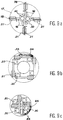
- FIG. 1B When the sailboat 1 is in space, the deployment of the sail begins (FIG. 1B) by the extension of the jack rod 3 which lifts the rollers 6 and frees them from jumpers 7 under which their ends were slid and which kept flat. Air is then blown into the mouthpieces 5.
- FIG. 1C the rollers 6 are unwound in a plane as and as the masts 8 inflate and straighten.
- Figure 1D shows the state where the rollers 6 have disappeared but where the masts 8 are not fully inflated; the rest of the deployment is illustrated in FIG. 1E and consists of a progressive unfolding of the stacks of folds 9 which formed the edges of the rollers 6 on either side of a central part 10.
- the masts 8 are then deployed by pivoting.
- FIG. 1F represents the final state of the sail: the masts 8 are arranged at the diagonals of the square and the sail 11 is deployed in a plane; the folds are gone.
- US-A-3,690,080 describes a device for rigid solar panels sliding on deployable rods.
- the panels are hinged together, which is only conceivable for rigid elements and very few, otherwise excessive jamming or friction seems inevitable.
- all the panels deploy at the same time, which is more difficult to accomplish correctly, and more risky for fragile elements, than a successive deployment of the panels.
- US-A-3,558,219 describes flexible radiation reflectors stretched over segments of a folding mast, which requires dividing the reflectors into parallel strips.
- the bands are folded back on themselves with a double winding which would impose, on a solar sail whose face exposed to the Sun is covered with a reflective coating and consequently generally conductive (aluminum based for Mylar bands for example ) to touch portions of this coating, with the risk of breakdown, tearing or other damage that electrostatic charges could cause.
- wing devices consists of a solar wing made up of a sail; substantially concurrent masts and connected to a sailboat by footings, the masts being able to be deployed from a state where they are folded up and stored on the sailboat by deployment devices located at the footings;
- the sail is made up of separate bands stretched between two consecutive masts at different places from the masts, the bands being rolled up when the masts are folded and connected to the masts by fasteners sliding on the masts which consist of rings threaded on the masts and connected together by ropes;
- the masts are elastic profiles which can be flattened and wound around winches forming part of the deployment devices.
- the advantage of this embodiment is to avoid folding the sail in any way while ensuring the staggered extraction of the strips from the place where they are stored in rolls, that is to say a good control of the process. deployment.
- An advantageous connection method consists of pivots having a pivot axis oriented in the direction of deployment of the bands, since the deployment of the sail is then very safe.
- the bases prefferably be formed so as to rotate between a position where the masts are substantially parallel and contiguous and a position for deploying the sail where the masts are substantially radiating and the sail belongs substantially to a plane.
- the sail takes the shape of an increasingly flattened pyramid when deployed; it actually opens like the petals of a flower. Provided that it is reversible, this arrangement makes it possible to modify at will the deployment of the sail and the shape of its projected surface towards the Sun, that is to say of participate in the orientation of the sailboat.
- a steering sail attached to a movable support can be added so that it can take different inclinations on the sail plane.
- the mobile support advantageously consists of one of the masts, which is then formed so as to be able to pivot in its root.
- the purpose of this steering sail is to adjust the speed of rotation about the axis perpendicular to the main plane of the sail.
- the sail 15 according to the invention is flat and square in the deployed state. It is stretched between four masts 16 located at the diagonals of the square and which compete towards almost identical root sites and located on a platform 17 of a sailboat 18.
- the sail 15 is divided by the masts 16 into four portions and formed of bands 19 contiguous and parallel to the adjoining side of the square.
- a steering sail 14 is stretched along a mast 16. It has a triangular shape and widens outwards as shown here, or inwards.
- the mast 16 which carries it is located on a median of the triangle.
- the steering sail 14 rotates around the mast 16 according to an angular displacement travel which can be a few tens of degrees.
- FIGS. 1 does not respect the actual proportions for reasons of clarity.
- the sail 15 actually has a span which can be ten or twenty times the dimensions of the body of the sailboat 18, as for the sailboat of FIGS. 1.
- the approximately circular platform 17 receives four bases 20 regularly distributed around its circumference.
- the bases 20 are the devices in which the masts 16 are embedded. Two of them, diametrically opposite, are surrounded by four compartments 21 in each of which the strips 19 of a respective part of the sail are stored before deployment in the rolled up state.
- the rollers are identified by the reference 22.
- Ropes 23 extend from the rollers 22 to the closest root 20 and other ropes 24 of greater length extend from the same rollers 22 to a root 20 a little more distant but close to the previous one.
- the strings 23 and 24 seem to disappear in the root plates 20. They actually end up at the masts 16 according to an arrangement which will be described later.
- An electronic box 25 which may include star sensors, antennas or other devices is advantageously placed in the center of the platform 17, but it does not necessarily have to do with the invention.
- a tilting support 26 capable of turning around an axis 28 controlled by a stepping motor 29 which can be powered from solar power generators.
- the axis 28 extends parallel to the platform 17 and in a circumferential direction and the tilting support 26 essentially carries a winch 30 composed of a drum 31 on which a mast 16 is wound in the folded state, a deployment system 32, a rolling mill 33 and a die 34.
- the deployment system 32 firstly comprises a motor 35, a reduction gear 36 at the output of the motor 35, and a motor shaft 37 at the output of the reduction gear 36 and which is capable of driving one or the other of two pulleys 38 and 39.
- the pulleys 38 and 39 are mounted on the drive shaft 37 by unidirectional clutches not shown so that they are crazy when the drive shaft 37 rotates in one direction (moreover opposite for the two pulleys 38 and 39), and are driven when the motor shaft 37 rotates in the other direction. This is why the engine 35 is reversible or the transmission 36 includes a reversing device.
- One of the pulleys 38 rotates the drum 31 by a first belt 40 and the other pulley 39 rotates a pinion 41 by a second belt 42.
- the rolling mill 33 consists of two parallel pressure rollers 43 and 44, close to each other and provided with toothed ends 45 and 46 forming a gear.
- the pinion 41 forms another gear with one of the toothed ends 45.
- the mast 16 is formed of an elastic profile whose section has a shape close to a tube.
- the masts 16 and the winch devices 30 in accordance with this description are manufactured by the Spanish company Sener for various applications in space vehicles; Patents WO-A-91 08 94 and the article "Solar Sail Engineering Development Mission” of the AIAA Student Journal in the summer issue of 1981, describe other uses of similar masts.
- the masts 16 can be made of cupro-beryllium or carbon fibers and their section is designed so that they can flatten in the plane of the ribs 48 until the portions in an arc of a circle 47 touch.
- the deformation is elastic so that the masts 16 resume their free section as soon as they can.
- the elasticity is not perfect if fibers of carbon are used because creeping occurs, but a satisfactory recovery is still obtained.
- the mast 16 is first of all flattened and wound around the drum 31. Only its free end protrudes from the winch 30. The section of the mast 16 straightens beyond the rolling mill 33 which is responsible for the flattening.
- the die 34 located at the end of the winch 30 is sufficiently distant from the rolling mill 33 so that the portion of the mast 16 which passes therein is in the fully straightened section. The purpose of the die 34 is in fact to support the mast 16 and to guide it when its deployment is decided.
- the motor 35 is then started so that the pulley 39 which drives the rolling mill 33 is driven.
- the mast 16 wound on the drum 31 is pulled outward by the rolling mill 33.
- the deployed part stiffens as the section straightens.
- the deployment of the masts 16 is continued until the airfoil is fully deployed.
- the deployment of the wing is normally irreversible.
- the winch 30 is also designed for other applications where it is necessary to fold the mast 16. This is why it includes the pulley 38, the control of which causes the mast 16 to be rewound on the drum 31 after it has been flattened through the rolling mill 33.
- This double control system from the drum 31 or the rolling mill 33 is useful so that the part of the mast 16 unrolled but still flattened between these two parts is never compressed, which would cause it to flare .
- the rollers 22 are housed side by side in the lockers 21; the material of the strips is wound around an axis 51, the ends of which are connected by two cords 23, and by two rings 52 to which the strings 23 are respectively linked, to a mast 16.
- the rings 52 are threaded on the mast 16 and slide along it; their spacing cannot exceed the length of spacers 53 which are formed by portions of a single rope 54 knotted on each ring 52 and also knotted at the free end 55 of the mast 16.
- the other cords 24 connect the ends of the outer edge 56 of the bands 19 to a mast 16 close to the previous one by an identical assembly comprising in particular rings 52 and spacers 53, which is moreover shown in FIGS. 6 and 7.
- the rings 52 are stacked on top of each other above the dies 34, around the ends of the masts 16 when the wing is folded.
- FIG. 6 illustrates the course
- only the masts 16 are deployed. They then extend parallel, in sheaf, the rollers 22 still intact hanging between them.
- the deployment of the masts 16 is accompanied by the staggered tensioning of the spacers 53, which extracts the rollers 22 one by one of the racks 21.
- the risks of incidents originating from an uncontrolled or poorly controlled deployment are therefore very reduced, and strings 23 and 24 are unlikely to get tangled.
- the rollers 22 are arranged side by side at determined locations, their axes 51 extending substantially.
- the strings 23 and 24 are all parallel to each other.
- the opening of the sail 15 or the extent of its projection onto a plane can be adjusted at any time by tilting each of the tilting supports 26 again.
- the center of thrust of the wing can be moved to bend the direction of travel of the sailboat 18 in the desired direction. No significant deformation is exerted on the bands 19.
- the steering sail 14 can be usefully added to the device if an assembly such as that of FIG. 8 is used, in which the winch 30 of the mast 16 which carries the steering sail 14 is mounted on a movable disc 57 which rotates around 'a fixed disc 58 linked to the tilting support 26.
- the movable disc 57 carries a motor 59 whose shaft is terminated by a pinion 60 which meshes in a circular rack 61 at the edge of the fixed disc 58.
- This device allows the mast 16 to pivot around its axis by sliding in the rings 52 so that the inclination of the steering sail 14 relative to the main sail 15 is modified.
- the free end 55 of the mast 16 concerned then carries a rotary crosspiece 62 around which the steering sail 14 is wound before the deployment of the wing.
- the masts 16 are not necessarily four in number and the sail may be a polygon other than a square.
- the material of the sail is indifferent and can be chosen from all those which are usual for this job.
- FIGS. 9a, 9b and 9c they have, in the folded state, sections taken out of the winches 30 which can be arranged in a star, in a polygon or overlapping and all extend substantially in the same plane and in their final direction of deployment.
- Two compartments 21 extend at the edge of the platform 17, on either side of each mast 16. The most convenient arrangement will be chosen for placing other possible devices on the platform 17.
- the shells 80 contain the bands 19, wound as above around axes 79 and the end of which comes out of the shells 80 through a slot 82.
- the other end of the strips 19 is attached to a bar 81 placed in a rack 21 associated with a neighboring mast 16.
- the strips 19 are therefore partially extended and stretched even before the deployment of the masts 16 and pass through days 83 of the lockers 21; they must bypass the winches 30 in the embodiments of FIGS. 9b and 9c and are therefore stretched on bypass piles 84.
- the pins 79 rotate freely in the shells 80 but a lock can block them before deployment. This lock may consist of a connecting means which breaks or breaks apart as soon as sufficient tension is imposed on the strip 19.
- the pins 79 and the bars 81 keep the strips 19 straight and prevent them from bending.
- the ends which are still out of the strips 19 have a reinforced thickness.
- Hulls 80 and bars 81 are connected to rings 85, which slide like the rings 52 along the masts 16 but are also provided with pivots 86 which connect them to the hulls 80 and to the bars 81.
- the pivots 86 extend in the band deployment plan 19 so that the shells 80 and the bars 81 can pivot between the position in FIG. 10, where they are all mutually parallel, contiguous and perpendicular to the masts 16, and the position in FIG. 11 where they are oblique to the masts 16, when the bands 19 are fully deployed.
- the pivoting movement is caused by slides 78 in the form of curved bars located near the outlet of the lockers 21 and which tilt the shells 80 and the bars 81.
- ropes 53 which connect the rings 85 together. It is advantageous for them to be housed in circular grooves 87 hollowed out at the edges of the rings 85, which can thus be perfectly contiguous and stacked before deployment without the cords 53 having any possibility of escaping.
- a lubricated sheath 88 can be interposed between the masts 16, at the location of the lockers 21, and the rings 85 to allow the latter to slide easily at the start of deployment.
- the cords 53 can be replaced by electric cables intended to supply an appliance at the end of the mast 16, such as the motor 94 which will be discussed.
- Such cables are composed of lengths connecting the rings 85, like the cords 53, and lengths (77 in FIG. 10) inserted in the holes of the rings 85 and which connect the previous ones.
- the means for retaining ropes 53 or cables are knots, staples or any other usual means.
- FIG. 12 represents a steering sail 90 which is like the main sail formed by bands 19 stretched between hulls 80 and bars 81.
- the hulls 80 and the bars 81 are articulated at the ends 91 and 92 of an extension mast 93 situated at the end of the mast 16 proper and which can consist of a telescopic system formed of nested elements and connected by springs that a pyrotechnic system can release.
- a folding mast wound around a winch like the mast 16 is however preferred because it can be folded, which offers the ability to vary the surface of the steering sail 90 and therefore to balance the thrust on the wing.
- the extension mast 93 pivots at the end of the mast 16 by a motor 94. It can be seen by comparing FIG. 12 to FIG.
Landscapes
- Engineering & Computer Science (AREA)
- Remote Sensing (AREA)
- Aviation & Aerospace Engineering (AREA)
- Life Sciences & Earth Sciences (AREA)
- Sustainable Development (AREA)
- Sustainable Energy (AREA)
- Chemical & Material Sciences (AREA)
- Combustion & Propulsion (AREA)
- Aerials With Secondary Devices (AREA)
- Wind Motors (AREA)
Applications Claiming Priority (2)
| Application Number | Priority Date | Filing Date | Title |
|---|---|---|---|
| FR9109504A FR2679515B1 (fr) | 1991-07-26 | 1991-07-26 | Voilure solaire. |
| FR9109504 | 1991-07-26 |
Publications (2)
| Publication Number | Publication Date |
|---|---|
| EP0524888A1 true EP0524888A1 (de) | 1993-01-27 |
| EP0524888B1 EP0524888B1 (de) | 1995-12-13 |
Family
ID=9415592
Family Applications (1)
| Application Number | Title | Priority Date | Filing Date |
|---|---|---|---|
| EP92402142A Expired - Lifetime EP0524888B1 (de) | 1991-07-26 | 1992-07-24 | Sonnensegel |
Country Status (3)
| Country | Link |
|---|---|
| EP (1) | EP0524888B1 (de) |
| DE (1) | DE69206704T2 (de) |
| FR (1) | FR2679515B1 (de) |
Cited By (12)
| Publication number | Priority date | Publication date | Assignee | Title |
|---|---|---|---|---|
| FR2704515A1 (fr) * | 1993-04-27 | 1994-11-04 | Centre Nat Etd Spatiales | Satellite artificiel muni de gouvernes aérodynamiques d'orientation. |
| FR2711111A1 (fr) * | 1993-10-12 | 1995-04-21 | Matra Marconi Space France | Engin spatial à voile solaire et procédé de pilotage d'un tel engin. |
| US5806801A (en) * | 1994-07-14 | 1998-09-15 | Orbital Sciences Corporation | Method and system for formationkeeping between orbiting spacecraft by varying their ballistic coefficients |
| EP1236643A3 (de) * | 2001-02-28 | 2003-05-28 | Deutsches Zentrum für Luft- und Raumfahrt e.V. | Vorrichtung mit einem im Querschnitt flach zusammengedrückten und der Länge nach aufgerollten Mast |
| FR2839949A1 (fr) * | 2002-05-22 | 2003-11-28 | Centre Nat Etd Spatiales | Procede d'assemblage dans l'espace d'un satellite artificiel constitue d'au moins deux modules et dispositif pour sa mise en oeuvre |
| GB2434345A (en) * | 2005-12-28 | 2007-07-25 | Frank Ellinghaus | Solar sail arrangement |
| GB2492879A (en) * | 2011-07-13 | 2013-01-16 | Frank Ellinghaus | A space based power station incorporating a solar sail |
| WO2020223733A1 (en) | 2019-05-02 | 2020-11-05 | L'garde, Inc. | Solar sail attachment and deployment methods |
| CN113764899A (zh) * | 2021-08-04 | 2021-12-07 | 同济大学 | 一种肋网式可展开天线的网面安装方法 |
| CN114348300A (zh) * | 2022-01-11 | 2022-04-15 | 沈阳航天新光集团有限公司 | 一种自动收放式太阳翼展开装置 |
| CN117329027A (zh) * | 2023-11-28 | 2024-01-02 | 成都志力科技发展有限责任公司 | 一种伸缩式尾喷管 |
| US20240300675A1 (en) * | 2016-05-05 | 2024-09-12 | L'garde, Inc. | Solar Sail for Orbital Maneuvers |
Families Citing this family (2)
| Publication number | Priority date | Publication date | Assignee | Title |
|---|---|---|---|---|
| WO2018157061A1 (en) * | 2017-02-27 | 2018-08-30 | River Front Services, Inc. | Structural tape deployment apparatus |
| CN113401367B (zh) * | 2021-06-28 | 2022-03-18 | 南京理工大学 | 一种微纳卫星太阳帆推进系统展开装置 |
Citations (5)
| Publication number | Priority date | Publication date | Assignee | Title |
|---|---|---|---|---|
| US3558219A (en) * | 1967-05-10 | 1971-01-26 | Westinghouse Electric Corp | Erectable reflector construction |
| US3690080A (en) * | 1970-09-21 | 1972-09-12 | Trw Inc | Solar array with self-erecting, self-rigidizing roll-up sheets |
| US3698958A (en) * | 1969-12-03 | 1972-10-17 | Trw Inc | Solar panel |
| EP0399055A1 (de) * | 1988-12-02 | 1990-11-28 | Institut Kosmicheskikh Issledovany Akademii Nauk Sssr | Raumfahrzeug |
| WO1991008949A2 (en) * | 1989-12-08 | 1991-06-27 | Cambridge Consultants Limited | Furlable sheet structures and methods of furling |
-
1991
- 1991-07-26 FR FR9109504A patent/FR2679515B1/fr not_active Expired - Fee Related
-
1992
- 1992-07-24 EP EP92402142A patent/EP0524888B1/de not_active Expired - Lifetime
- 1992-07-24 DE DE69206704T patent/DE69206704T2/de not_active Expired - Fee Related
Patent Citations (5)
| Publication number | Priority date | Publication date | Assignee | Title |
|---|---|---|---|---|
| US3558219A (en) * | 1967-05-10 | 1971-01-26 | Westinghouse Electric Corp | Erectable reflector construction |
| US3698958A (en) * | 1969-12-03 | 1972-10-17 | Trw Inc | Solar panel |
| US3690080A (en) * | 1970-09-21 | 1972-09-12 | Trw Inc | Solar array with self-erecting, self-rigidizing roll-up sheets |
| EP0399055A1 (de) * | 1988-12-02 | 1990-11-28 | Institut Kosmicheskikh Issledovany Akademii Nauk Sssr | Raumfahrzeug |
| WO1991008949A2 (en) * | 1989-12-08 | 1991-06-27 | Cambridge Consultants Limited | Furlable sheet structures and methods of furling |
Non-Patent Citations (1)
| Title |
|---|
| AIAA STUDENT JOURNAL Juillet 1981, CALIFORNIA (USA) pages 14 - 18 PRICE, H.W. 'SOLAR SAIL ENGINEERING DEVELOPMENT MISSION' * |
Cited By (19)
| Publication number | Priority date | Publication date | Assignee | Title |
|---|---|---|---|---|
| FR2704515A1 (fr) * | 1993-04-27 | 1994-11-04 | Centre Nat Etd Spatiales | Satellite artificiel muni de gouvernes aérodynamiques d'orientation. |
| WO1994025344A1 (fr) * | 1993-04-27 | 1994-11-10 | Centre National D'etudes Spatiales | Satellite artificiel muni de gouvernes aerodynamiques d'orientation |
| FR2711111A1 (fr) * | 1993-10-12 | 1995-04-21 | Matra Marconi Space France | Engin spatial à voile solaire et procédé de pilotage d'un tel engin. |
| US5806801A (en) * | 1994-07-14 | 1998-09-15 | Orbital Sciences Corporation | Method and system for formationkeeping between orbiting spacecraft by varying their ballistic coefficients |
| EP1236643A3 (de) * | 2001-02-28 | 2003-05-28 | Deutsches Zentrum für Luft- und Raumfahrt e.V. | Vorrichtung mit einem im Querschnitt flach zusammengedrückten und der Länge nach aufgerollten Mast |
| US6843029B2 (en) | 2001-02-28 | 2005-01-18 | Deutches Zentrum für Luft-und Raumfahrt e.V. | Apparatus including a boom to be compressed and rolled up |
| FR2839949A1 (fr) * | 2002-05-22 | 2003-11-28 | Centre Nat Etd Spatiales | Procede d'assemblage dans l'espace d'un satellite artificiel constitue d'au moins deux modules et dispositif pour sa mise en oeuvre |
| GB2434345B (en) * | 2005-12-28 | 2008-04-09 | Frank Ellinghaus | Solar-sail-launch-system, comprising a launch vehicle and a solar sail mothership spacecraft with "roller-reefing"-ACS and solar electric propulsion. |
| GB2434345A (en) * | 2005-12-28 | 2007-07-25 | Frank Ellinghaus | Solar sail arrangement |
| GB2492879A (en) * | 2011-07-13 | 2013-01-16 | Frank Ellinghaus | A space based power station incorporating a solar sail |
| GB2492879B (en) * | 2011-07-13 | 2014-04-02 | Frank Ellinghaus | Mobile solar sail powerstation and coupled solar sail powerstations for space based power generation and transmission |
| US20240300675A1 (en) * | 2016-05-05 | 2024-09-12 | L'garde, Inc. | Solar Sail for Orbital Maneuvers |
| WO2020223733A1 (en) | 2019-05-02 | 2020-11-05 | L'garde, Inc. | Solar sail attachment and deployment methods |
| EP3962815A4 (de) * | 2019-05-02 | 2023-01-18 | L'garde, Inc. | Sonnensegelbefestigung und einsetzverfahren |
| US12084207B2 (en) | 2019-05-02 | 2024-09-10 | L'garde, Inc. | Solar sail attachment and deployment methods |
| CN113764899A (zh) * | 2021-08-04 | 2021-12-07 | 同济大学 | 一种肋网式可展开天线的网面安装方法 |
| CN114348300A (zh) * | 2022-01-11 | 2022-04-15 | 沈阳航天新光集团有限公司 | 一种自动收放式太阳翼展开装置 |
| CN117329027A (zh) * | 2023-11-28 | 2024-01-02 | 成都志力科技发展有限责任公司 | 一种伸缩式尾喷管 |
| CN117329027B (zh) * | 2023-11-28 | 2024-01-26 | 成都志力科技发展有限责任公司 | 一种伸缩式尾喷管 |
Also Published As
| Publication number | Publication date |
|---|---|
| DE69206704T2 (de) | 1996-07-04 |
| DE69206704D1 (de) | 1996-01-25 |
| FR2679515A1 (fr) | 1993-01-29 |
| EP0524888B1 (de) | 1995-12-13 |
| FR2679515B1 (fr) | 1996-01-26 |
Similar Documents
| Publication | Publication Date | Title |
|---|---|---|
| EP0524888B1 (de) | Sonnensegel | |
| RU2232111C2 (ru) | Мембранная космическая конструкция и способ ее развертывания и раскрытия | |
| CA2834593C (fr) | Dispositif de deploiement et de reploiement d'une structure flexible, structure deployable flexible et satellite munis d'un tel dispositif | |
| EP2977323B1 (de) | Entfaltbare struktur mit federband | |
| EP2977322B1 (de) | Verfahren zum versenkbaren einbau eines massbands für eine entfaltbare struktur, und entfaltbare struktur mit massband | |
| US4030102A (en) | Deployable reflector structure | |
| EP2471714B1 (de) | Abrollbarer ebener Solargenerator | |
| FR2596205A1 (fr) | Ensemble et appareil de deploiement de structures pliees, telles que des antennes | |
| EP3023333B1 (de) | Ausfahrbare und einziehbare struktur mit massband | |
| FR2654799A1 (fr) | Support telescopique. | |
| EP3176095B1 (de) | Ausklappbare struktur, die eine gesamtheit von solargeneratoren umfasst, ausklappsystem einer solchen ausklappbaren struktur und satellit, der ein solches system umfasst | |
| FR2932709A1 (fr) | Structure articulee deployable | |
| EP2993131A1 (de) | Ausfahrbarer mast mit autonomer spontaner ausfahrbewegung, und satellit, der mit mindestens einem solchen mast ausgestattet ist | |
| CN110313106A (zh) | 可展开缠绕肋组件 | |
| CA2750048A1 (fr) | Turbinolienne energetique | |
| WO2003004356A2 (en) | Space craft and methods for space travel | |
| EP0078230A1 (de) | Einrichtung zum Aufrollen und Aufbewahren von Segeln | |
| FR2508413A1 (fr) | Ensembles de feuilles deployables pour engin spatial | |
| EP2520494B1 (de) | Vorrichtung zum Schutz eines optischen Vielfachspiegelinstruments | |
| FR3095022A1 (fr) | Système de freinage ainsi que procédé et dispositif pour déployer un corps creux de forme allongée enroulé | |
| JP4877809B2 (ja) | 展開型アンテナ | |
| FR2589982A1 (fr) | Structure pliable, notamment pour l'espace | |
| FR2466652A1 (fr) | Fleche telescopique | |
| FR2711111A1 (fr) | Engin spatial à voile solaire et procédé de pilotage d'un tel engin. | |
| EP2027016B1 (de) | System zum entfalten von raumansatzteilen und solch ein system umfassende raumansatzteile |
Legal Events
| Date | Code | Title | Description |
|---|---|---|---|
| PUAI | Public reference made under article 153(3) epc to a published international application that has entered the european phase |
Free format text: ORIGINAL CODE: 0009012 |
|
| AK | Designated contracting states |
Kind code of ref document: A1 Designated state(s): DE FR GB |
|
| 17P | Request for examination filed |
Effective date: 19930702 |
|
| 17Q | First examination report despatched |
Effective date: 19940722 |
|
| GRAA | (expected) grant |
Free format text: ORIGINAL CODE: 0009210 |
|
| AK | Designated contracting states |
Kind code of ref document: B1 Designated state(s): DE FR GB |
|
| REF | Corresponds to: |
Ref document number: 69206704 Country of ref document: DE Date of ref document: 19960125 |
|
| GBT | Gb: translation of ep patent filed (gb section 77(6)(a)/1977) |
Effective date: 19960305 |
|
| PLBE | No opposition filed within time limit |
Free format text: ORIGINAL CODE: 0009261 |
|
| STAA | Information on the status of an ep patent application or granted ep patent |
Free format text: STATUS: NO OPPOSITION FILED WITHIN TIME LIMIT |
|
| 26N | No opposition filed | ||
| REG | Reference to a national code |
Ref country code: GB Ref legal event code: IF02 |
|
| PGFP | Annual fee paid to national office [announced via postgrant information from national office to epo] |
Ref country code: GB Payment date: 20020724 Year of fee payment: 11 |
|
| PGFP | Annual fee paid to national office [announced via postgrant information from national office to epo] |
Ref country code: FR Payment date: 20020725 Year of fee payment: 11 Ref country code: DE Payment date: 20020725 Year of fee payment: 11 |
|
| PG25 | Lapsed in a contracting state [announced via postgrant information from national office to epo] |
Ref country code: GB Free format text: LAPSE BECAUSE OF NON-PAYMENT OF DUE FEES Effective date: 20030724 |
|
| PG25 | Lapsed in a contracting state [announced via postgrant information from national office to epo] |
Ref country code: DE Free format text: LAPSE BECAUSE OF NON-PAYMENT OF DUE FEES Effective date: 20040203 |
|
| GBPC | Gb: european patent ceased through non-payment of renewal fee |
Effective date: 20030724 |
|
| PG25 | Lapsed in a contracting state [announced via postgrant information from national office to epo] |
Ref country code: FR Free format text: LAPSE BECAUSE OF NON-PAYMENT OF DUE FEES Effective date: 20040331 |
|
| REG | Reference to a national code |
Ref country code: FR Ref legal event code: ST |