EP0524876A1 - Roues à aubes de turbomachines - Google Patents
Roues à aubes de turbomachines Download PDFInfo
- Publication number
- EP0524876A1 EP0524876A1 EP92402110A EP92402110A EP0524876A1 EP 0524876 A1 EP0524876 A1 EP 0524876A1 EP 92402110 A EP92402110 A EP 92402110A EP 92402110 A EP92402110 A EP 92402110A EP 0524876 A1 EP0524876 A1 EP 0524876A1
- Authority
- EP
- European Patent Office
- Prior art keywords
- disc
- blades
- crown
- ferrule
- vanes
- Prior art date
- Legal status (The legal status is an assumption and is not a legal conclusion. Google has not performed a legal analysis and makes no representation as to the accuracy of the status listed.)
- Withdrawn
Links
- 238000007373 indentation Methods 0.000 claims description 7
- 239000002131 composite material Substances 0.000 claims description 5
- 210000003462 vein Anatomy 0.000 claims description 4
- 238000005553 drilling Methods 0.000 claims 1
- 239000007789 gas Substances 0.000 description 5
- 238000004519 manufacturing process Methods 0.000 description 3
- 238000010276 construction Methods 0.000 description 2
- 238000006073 displacement reaction Methods 0.000 description 2
- 230000002093 peripheral effect Effects 0.000 description 2
- 239000006096 absorbing agent Substances 0.000 description 1
- 238000012423 maintenance Methods 0.000 description 1
- 239000000463 material Substances 0.000 description 1
- 238000000034 method Methods 0.000 description 1
- 230000035939 shock Effects 0.000 description 1
Images
Classifications
-
- F—MECHANICAL ENGINEERING; LIGHTING; HEATING; WEAPONS; BLASTING
- F01—MACHINES OR ENGINES IN GENERAL; ENGINE PLANTS IN GENERAL; STEAM ENGINES
- F01D—NON-POSITIVE DISPLACEMENT MACHINES OR ENGINES, e.g. STEAM TURBINES
- F01D11/00—Preventing or minimising internal leakage of working-fluid, e.g. between stages
- F01D11/005—Sealing means between non relatively rotating elements
- F01D11/006—Sealing the gap between rotor blades or blades and rotor
- F01D11/008—Sealing the gap between rotor blades or blades and rotor by spacer elements between the blades, e.g. independent interblade platforms
Definitions
- the invention relates to improvements to the impellers of turbomachinery and in particular to the wheels of turbines and compressors used in aeronautics.
- turbomachine wheel of the type comprising a disc or drum, a plurality of profiled blades extending radially outward from the periphery of said disc and the feet of which are locked on said disc, and a crown. coaxial with said disc and independent of said vanes, said crown forming between said vanes platforms delimiting the internal wall of the aerodynamic gas circulation stream.
- the blades are mounted on discs having diameters which can be relatively small. These blades are also produced from composite or other materials which resist high temperatures and high centrifugal forces. For reasons of manufacturing cost, these composite material blades are produced without platforms and have an aerodynamic profile from their foot to their head.
- the high volume of gases circulating in the aerodynamic annular vein means that this annular vein has to be given an internal diameter greater than the diameter of the discs carrying the blades, so as to avoid excessive turbulence in the vicinity of the internal wall delimiting the aerodynamic vein. This is why we create around the disc, a crown with platforms between the blades.
- This independent crown of the blades also allows the disc to be moved away from high temperature zones.
- the crown is produced by added elements, distinct from the blades and fixed to the disc, the number of these added elements being equal to the number of blades.
- US Patent 2,834,573 shows a rotor in which a ring fills the peripheral space existing between the blades.
- This ring consists of elementary segments, shown in Figure 6, which leaves between them a housing corresponding to the profile of the blade.
- French patent 1,501,492 relates to a compressor wheel, equipped with blades without platform, and comprising an annular ring having multiple recesses angularly spaced to accommodate the respective heels of the blades.
- the crown also includes multiple segments. Each segment is made integral with the wheel on which it is mounted by a fastener fixed in a peripheral groove.
- French patent 2,073,854 describes a rotor in which the intermediate pieces play the role of platforms with respect to the flow, the primary purpose of these intermediate pieces being a mechanical role of shock absorber. These intermediate pieces are maintained, between the blade roots and the edges of the cells, by corner systems.
- French patent 2,608,674 relates to a turbine wheel which comprises vanes having a bulbous-shaped foot, the lateral planar sides of which have a small convergence angle and are held in the cells by wedge-shaped elements associated with elements distinct forming platforms to form a continuous ring of internal wall of the aerodynamic gas stream.
- the object of the present invention is to propose a new type of crown which appreciably reduces the number of parts present.
- said crown consists of an annular ferrule having indentations for the passage of the blades.
- said crown is made of composite materials.
- This new structure of the crown makes it possible to lighten the means for fixing the crown to the disc. It can be applied to discs provided with grooves for attachments of so-called "hammer” blades, and to discs on which the blades are pinned.
- impressions are preferably made by piercing the shell by a specific process. According to a construction variant, they are produced in the form of open slots on an edge of said ferrule.
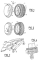
- the drawing shows a crown 2 made in one part and made of composite materials and in the form of an annular ferrule capable of being arranged coaxially on a disc 3 of a turbomachine, not shown in the drawing, so as to constitute the internal wall of the aerodynamic circulation stream gases through the turbomachine.
- This ferrule 2 has a plurality of indentations 4 intended for the passage of the vanes 5, the feet 6 of which are fixed to the periphery 7 of the disc 3.
- These indentations 4 may be in the form of holes made during the manufacture of the crown. 2, as seen in Figures 1 and 2.
- the blades 5 have an aerodynamic profile over their entire length.
- FIG. 1 shows an exploded view of a turbomachine wheel in which the attachment of the blades 5 to the disc 3 is of the "hammer attachment" type.
- the disc 3 has, in known manner, on its periphery 7, annular grooves 8 forming cells intended to receive the feet 6 of the blades 5, and an introduction window 9 for mounting and dismounting the blades 5.
- the mounting of the first dawn 5 is done as follows: the ferrule 2 is positioned on the disc 3 by placing an imprint 4 opposite the introduction window 9; the foot 6 of the first blade 5 is introduced from the outside of the ferrule into said introduction window 9 by passing it through the cavity 4 in correspondence and; the assembly constituted by the ferrule 2 and the first blade 5 is subjected to rotation about the axis of the disc 3 by an angle corresponding to the angular spacing of two consecutive indentations 4; the following blades 5 are assembled by introducing a blade root 6 into the introduction window 9 and rotating a step of the crown 2.
- FIG. 2 shows an exploded view of a turbomachine wheel in which the attachment of the blades 5 to the disc 3 is of the brocaded type.
- the disc 3 has on its periphery 7 axial cells 10 in which the feet 6 of the blades 5 are introduced.
- the heads of all the vanes 6 are passed through the interior of the ferrule 2 through the cavities 4, then all the vanes 5 are assembled at the same time. translation of the assembly constituted by the crown 2 and the assembly of all the blades 5, coaxially with the disc 3.
- FIGS 3 and 4 show an alternative embodiment of the crown 2 of the invention.
- the ferrule is notched and the imprints 4 is in the form of slots 11 open on an edge 12 of the ferrule 2.
- the blades 5 are first introduced into the cells of the disc 3, then the ferrule 2 is positioned.
- the assembly is secured to the disc 3 by a segment 13 disposed downstream of the disc 3 and cooperating with the edge 12 of the ferrule 2 .
- FIGS. 1 and 2 can be extended to several stages of wheels depending on the taper of the aerodynamic stream.
- the ferrule 2 can be secured to the disc 3 by screws, not shown in the drawing, cooperating with bores 14 and 15 provided in correspondence on the shell 2 and the disc 3.
Landscapes
- Engineering & Computer Science (AREA)
- Mechanical Engineering (AREA)
- General Engineering & Computer Science (AREA)
- Structures Of Non-Positive Displacement Pumps (AREA)
- Turbine Rotor Nozzle Sealing (AREA)
Applications Claiming Priority (2)
| Application Number | Priority Date | Filing Date | Title |
|---|---|---|---|
| FR9109368 | 1991-07-24 | ||
| FR9109368A FR2679599A1 (fr) | 1991-07-24 | 1991-07-24 | Perfectionnement aux roues a aubes de turbomachines. |
Publications (1)
| Publication Number | Publication Date |
|---|---|
| EP0524876A1 true EP0524876A1 (fr) | 1993-01-27 |
Family
ID=9415486
Family Applications (1)
| Application Number | Title | Priority Date | Filing Date |
|---|---|---|---|
| EP92402110A Withdrawn EP0524876A1 (fr) | 1991-07-24 | 1992-07-22 | Roues à aubes de turbomachines |
Country Status (3)
| Country | Link |
|---|---|
| US (1) | US5263823A (enExample) |
| EP (1) | EP0524876A1 (enExample) |
| FR (1) | FR2679599A1 (enExample) |
Cited By (4)
| Publication number | Priority date | Publication date | Assignee | Title |
|---|---|---|---|---|
| EP2075417A1 (fr) | 2007-12-27 | 2009-07-01 | Techspace aero | Plateforme et aube pour une roue aubagée de turbomachine, roue aubagée et compresseur ou turbomachine comportant une telle roue aubagée |
| FR2940350A1 (fr) * | 2008-12-23 | 2010-06-25 | Snecma | Roue mobile de turbomachine a aubes en materiau composite munie d'un anneau ressort. |
| FR2940353A1 (fr) * | 2008-12-23 | 2010-06-25 | Snecma | Roue mobile de turbomachine a aubes en materiau composite. |
| EP3683450A1 (fr) * | 2019-01-18 | 2020-07-22 | Safran Aero Boosters S.A. | Ensemble rotatif de turbomachine |
Families Citing this family (41)
| Publication number | Priority date | Publication date | Assignee | Title |
|---|---|---|---|---|
| GB9405473D0 (en) * | 1994-03-19 | 1994-05-04 | Rolls Royce Plc | A gas turbine engine fan blade assembly |
| US5609471A (en) * | 1995-12-07 | 1997-03-11 | Allison Advanced Development Company, Inc. | Multiproperty rotor disk and method of manufacture |
| US5597290A (en) * | 1996-05-01 | 1997-01-28 | Tuthill Corporation | Multi-component fan assembly |
| FR2772096B1 (fr) | 1997-12-09 | 2000-03-10 | Bosch Syst Freinage | Frein a tambour combinant le point fixe et la commande du frein de stationnement |
| US6139277A (en) * | 1998-12-22 | 2000-10-31 | Air Concepts, Inc. | Motorized fan |
| US6991428B2 (en) | 2003-06-12 | 2006-01-31 | Pratt & Whitney Canada Corp. | Fan blade platform feature for improved blade-off performance |
| DE10358421A1 (de) * | 2003-12-13 | 2005-07-07 | Mtu Aero Engines Gmbh | Rotor für eine Turbomaschine |
| IT1394295B1 (it) | 2009-05-08 | 2012-06-06 | Nuovo Pignone Spa | Girante centrifuga del tipo chiuso per turbomacchine, componente per tale girante, turbomacchina provvista di tale girante e metodo di realizzazione di tale girante |
| DE102009023841A1 (de) * | 2009-06-04 | 2010-12-09 | Mtu Aero Engines Gmbh | Integraler Rotor einer Strömungsmaschine mit separatem Deckband |
| DE102009023840A1 (de) * | 2009-06-04 | 2010-12-09 | Mtu Aero Engines Gmbh | Rotor einer Strömungsmaschine mit separatem Deckband |
| IT1397057B1 (it) | 2009-11-23 | 2012-12-28 | Nuovo Pignone Spa | Girante centrifuga e turbomacchina |
| IT1397058B1 (it) | 2009-11-23 | 2012-12-28 | Nuovo Pignone Spa | Stampo per girante centrifuga, inserti per stampo e metodo per costruire una girante centrifuga |
| DE102010015404B4 (de) * | 2010-04-19 | 2012-02-16 | Mtu Aero Engines Gmbh | Verfahren zur Reparatur einer Rotoranordnung einer Turbomaschine, Ringelement für eine Rotoranordnung einer Turbomaschine sowie Rotoranordnung für eine Turbomaschine |
| FR2961847B1 (fr) * | 2010-06-25 | 2012-08-17 | Snecma | Roue mobile a aubes en materiau composite pour moteur a turbine a gaz a liaison pied d'aube/disque par serrage |
| US8491267B2 (en) | 2010-08-27 | 2013-07-23 | Pratt & Whitney Canada Corp. | Retaining ring arrangement for a rotary assembly |
| ITCO20110064A1 (it) | 2011-12-14 | 2013-06-15 | Nuovo Pignone Spa | Macchina rotante comprendente un rotore con una girante composita ed un albero metallico |
| US9376926B2 (en) * | 2012-11-15 | 2016-06-28 | United Technologies Corporation | Gas turbine engine fan blade lock assembly |
| FR3010442B1 (fr) * | 2013-09-09 | 2015-10-09 | Snecma | Disque aubage monobloc a contraintes reduites en pied d'aube, de preference pour soufflante de turbomachine d'aeronef |
| EP3071793B1 (en) * | 2013-11-22 | 2020-01-22 | United Technologies Corporation | Multi-material turbine airfoil |
| ITCO20130067A1 (it) | 2013-12-17 | 2015-06-18 | Nuovo Pignone Srl | Girante con elementi di protezione e compressore centrifugo |
| EP2933436A1 (de) * | 2014-04-15 | 2015-10-21 | Siemens Aktiengesellschaft | Radscheibe mit wenigstens einem Dichtblech |
| US10280768B2 (en) | 2014-11-12 | 2019-05-07 | Rolls-Royce North American Technologies Inc. | Turbine blisk including ceramic matrix composite blades and methods of manufacture |
| US9909430B2 (en) | 2014-11-13 | 2018-03-06 | Rolls-Royce North American Technologies Inc. | Turbine disk assembly including seperable platforms for blade attachment |
| US10047763B2 (en) | 2015-12-14 | 2018-08-14 | General Electric Company | Rotor assembly for use in a turbofan engine and method of assembling |
| FR3057908B1 (fr) * | 2016-10-21 | 2019-11-22 | Safran Aircraft Engines | Ensemble rotatif d'une turbomachine muni d'un systeme de maintien axial d'une aube |
| US10294954B2 (en) | 2016-11-09 | 2019-05-21 | Rolls-Royce North American Technologies Inc. | Composite blisk |
| US10563665B2 (en) | 2017-01-30 | 2020-02-18 | Rolls-Royce North American Technologies, Inc. | Turbomachine stage and method of making same |
| GB201718600D0 (en) * | 2017-11-10 | 2017-12-27 | Rolls Royce Plc | Annulus filler |
| US10738630B2 (en) * | 2018-02-19 | 2020-08-11 | General Electric Company | Platform apparatus for propulsion rotor |
| US10934859B2 (en) * | 2018-08-24 | 2021-03-02 | Rolls-Royce North American Technologies Inc. | Turbine blade comprising ceramic matrix composite materials |
| JP2024508185A (ja) | 2021-03-03 | 2024-02-22 | ウィスパー エアロ インコーポレイテッド | 推進ファンと駆動システム |
| CN117178111A (zh) * | 2021-03-03 | 2023-12-05 | 耳语航空公司 | 螺旋桨翼尾缘排气区域控制 |
| US12006891B2 (en) | 2021-03-03 | 2024-06-11 | Whisper Aero Inc. | Propulsor wing trailing edge exhaust area control |
| CN115194402A (zh) * | 2022-07-20 | 2022-10-18 | 华能国际电力股份有限公司 | 一种轮盘部件修复方法 |
| CN115213627B (zh) * | 2022-07-20 | 2023-05-05 | 华能国际电力股份有限公司 | 一种用于修复菌型叶根轮盘损伤的装置及装配方法 |
| CN114986078B (zh) * | 2022-07-20 | 2023-05-05 | 华能国际电力股份有限公司 | 一种用于修复t型叶根轮盘损伤的装置及装配方法 |
| CN115106715B (zh) * | 2022-07-20 | 2023-05-05 | 华能国际电力股份有限公司 | 一种用于修复叉型叶根轮盘损伤的装置及装配方法 |
| CN115178962A (zh) * | 2022-07-20 | 2022-10-14 | 华能国际电力股份有限公司 | 一种用于修复枞树型叶根轮盘损伤的装置及装配方法 |
| US12012857B2 (en) * | 2022-10-14 | 2024-06-18 | Rtx Corporation | Platform for an airfoil of a gas turbine engine |
| US20250089633A1 (en) | 2023-09-20 | 2025-03-20 | Whisper Aero Inc. | Air-moving device with multiple fan systems |
| US12071861B1 (en) * | 2023-09-22 | 2024-08-27 | Rolls-Royce American Technologies Inc. | Multi-piece radial turbine rotor |
Citations (3)
| Publication number | Priority date | Publication date | Assignee | Title |
|---|---|---|---|---|
| FR319370A (fr) * | 1902-03-07 | 1902-11-11 | Fullagar | Perfectionnements apportés aux turbines à fluide sous pression et aux turbo-pompes |
| US2918253A (en) * | 1956-05-18 | 1959-12-22 | Orenda Engines Ltd | Rotor assemblies for turbines |
| US2948505A (en) * | 1956-12-26 | 1960-08-09 | Gen Electric | Gas turbine rotor |
Family Cites Families (8)
| Publication number | Priority date | Publication date | Assignee | Title |
|---|---|---|---|---|
| US922581A (en) * | 1908-01-22 | 1909-05-25 | Gen Electric | Elastic-fluid turbine. |
| US2834573A (en) * | 1953-06-23 | 1958-05-13 | Stalker Dev Company | Rotor construction for fluid machines |
| US2988324A (en) * | 1957-06-14 | 1961-06-13 | Napier & Son Ltd | Rotors for multi-stage axial flow compressors or turbines |
| GB1093568A (en) * | 1965-11-23 | 1967-12-06 | Rolls Royce | Improvements in or relating to bladed rotors such as compressor rotors |
| US3554668A (en) * | 1969-05-12 | 1971-01-12 | Gen Motors Corp | Turbomachine rotor |
| GB1276106A (en) * | 1969-12-19 | 1972-06-01 | Rolls Royce | FLUID FLOW MACHINE, e.g. GAS TURBINE ENGINE COMPRESSOR |
| FR2608674B1 (fr) * | 1986-12-17 | 1991-04-19 | Snecma | Roue de turbine a aubes ceramique |
| US5030063A (en) * | 1990-02-08 | 1991-07-09 | General Motors Corporation | Turbomachine rotor |
-
1991
- 1991-07-24 FR FR9109368A patent/FR2679599A1/fr active Granted
-
1992
- 1992-07-22 EP EP92402110A patent/EP0524876A1/fr not_active Withdrawn
- 1992-07-22 US US07/917,181 patent/US5263823A/en not_active Expired - Lifetime
Patent Citations (3)
| Publication number | Priority date | Publication date | Assignee | Title |
|---|---|---|---|---|
| FR319370A (fr) * | 1902-03-07 | 1902-11-11 | Fullagar | Perfectionnements apportés aux turbines à fluide sous pression et aux turbo-pompes |
| US2918253A (en) * | 1956-05-18 | 1959-12-22 | Orenda Engines Ltd | Rotor assemblies for turbines |
| US2948505A (en) * | 1956-12-26 | 1960-08-09 | Gen Electric | Gas turbine rotor |
Cited By (9)
| Publication number | Priority date | Publication date | Assignee | Title |
|---|---|---|---|---|
| EP2075417A1 (fr) | 2007-12-27 | 2009-07-01 | Techspace aero | Plateforme et aube pour une roue aubagée de turbomachine, roue aubagée et compresseur ou turbomachine comportant une telle roue aubagée |
| US8348619B2 (en) | 2007-12-27 | 2013-01-08 | Techspace Aero | Platform and blade for a bladed wheel of a turbomachine, bladed wheel and compressor or turbomachine comprising such a bladed wheel |
| FR2940350A1 (fr) * | 2008-12-23 | 2010-06-25 | Snecma | Roue mobile de turbomachine a aubes en materiau composite munie d'un anneau ressort. |
| FR2940353A1 (fr) * | 2008-12-23 | 2010-06-25 | Snecma | Roue mobile de turbomachine a aubes en materiau composite. |
| WO2010072968A1 (fr) * | 2008-12-23 | 2010-07-01 | Snecma | Roue mobile de turbomachine a aubes en materiau composite munie d'un anneau ressort |
| US8282355B2 (en) | 2008-12-23 | 2012-10-09 | Snecma | Turbomachine rotor wheel having composite material blades |
| US8905710B2 (en) | 2008-12-23 | 2014-12-09 | Snecma | Turbine engine rotor wheel with blades made of a composite material provided with a spring ring |
| EP3683450A1 (fr) * | 2019-01-18 | 2020-07-22 | Safran Aero Boosters S.A. | Ensemble rotatif de turbomachine |
| BE1026984B1 (fr) * | 2019-01-18 | 2020-08-25 | Safran Aero Boosters Sa | Ensemble rotatif de turbomachine |
Also Published As
| Publication number | Publication date |
|---|---|
| FR2679599B1 (enExample) | 1995-01-20 |
| US5263823A (en) | 1993-11-23 |
| FR2679599A1 (fr) | 1993-01-29 |
Similar Documents
| Publication | Publication Date | Title |
|---|---|---|
| EP0524876A1 (fr) | Roues à aubes de turbomachines | |
| EP2801702B1 (fr) | Virole interne de redresseur de turbomachine avec joint abradable | |
| EP2268926B1 (fr) | Carter pour roue a aubes mobiles de turbomachine | |
| EP2112326B1 (fr) | Carter de turbomachine comportant un dispositif empêchant une instabilité lors d'un contact entre le carter et le rotor | |
| FR2617907A1 (fr) | Moteur a turbine a gaz | |
| CA2966126C (fr) | Ensemble rotatif pour turbomachine comprenant une virole de rotor auto-portee | |
| CA2442952C (fr) | Tambour formant en particulier un rotor de turbo machine, compresseur et turbo moteur comprenant un tel tambour | |
| FR2645902A1 (fr) | Masselotte d'equilibrage sans boulons pour des rotors de turbine | |
| FR2490722A1 (fr) | Joints d'etancheite a l'air pour turbomachines | |
| EP0140737A1 (fr) | Disque de compresseur avec accélérateur centripète intégré pour l'aspiration d'air dans un dispositif de refroidissement d'une turbine à gaz | |
| EP4185521B1 (fr) | Turbomachine d'aeronef comportant des aubes d'helice a calage variable | |
| FR2935736A1 (fr) | Aube rotative de turbine a vapeur et section basse pression d'un moteur a turbine a vapeur | |
| CA2569564C (fr) | Distributeur de turbine de turbomachine ameliore | |
| WO2016097632A1 (fr) | Ensemble de turbine de turbomachine d'aéronef | |
| EP3594503B1 (fr) | Turbomachine | |
| FR3029961A1 (fr) | Roue a aubes avec becquets pour une turbine de turbomachine | |
| CA2977896C (fr) | Disque aubage monobloc comportant un moyeu ayant une face evidee a laquelle est rapporte un organe de comblement | |
| EP0429353B1 (fr) | Rotor de turbomachine à flux axial | |
| FR3120650A1 (fr) | Turbomachine d’aeronef comportant des aubes d’helice a calage variable | |
| EP3797224A1 (fr) | Disque ameliore de soufflante de turbomachine | |
| FR3147327A1 (fr) | Turbomachine comprenant des rangees d’aubes statoriques et un diffuseur dans un canal où circule un troisieme flux. | |
| EP1319805A1 (fr) | Rotor ou élément rotorique pour turbocompresseur | |
| FR3109795A1 (fr) | Carter intermediaire de redressement avec bras structural monobloc | |
| WO2019197750A1 (fr) | Turbomachine comportant un dispositif d'amelioration du refroidissement de disques de rotor par un flux d'air | |
| FR3160725A1 (fr) | Ensemble statorique de turbine de turbomachine d’aeronef, presentant un flux d’air de purge statorique a efficacite renforcee |
Legal Events
| Date | Code | Title | Description |
|---|---|---|---|
| PUAI | Public reference made under article 153(3) epc to a published international application that has entered the european phase |
Free format text: ORIGINAL CODE: 0009012 |
|
| 17P | Request for examination filed |
Effective date: 19920812 |
|
| AK | Designated contracting states |
Kind code of ref document: A1 Designated state(s): DE FR GB |
|
| 17Q | First examination report despatched |
Effective date: 19940209 |
|
| STAA | Information on the status of an ep patent application or granted ep patent |
Free format text: STATUS: THE APPLICATION IS DEEMED TO BE WITHDRAWN |
|
| 18D | Application deemed to be withdrawn |
Effective date: 19940621 |