EP0524820A2 - Membranpumpe - Google Patents
Membranpumpe Download PDFInfo
- Publication number
- EP0524820A2 EP0524820A2 EP92306727A EP92306727A EP0524820A2 EP 0524820 A2 EP0524820 A2 EP 0524820A2 EP 92306727 A EP92306727 A EP 92306727A EP 92306727 A EP92306727 A EP 92306727A EP 0524820 A2 EP0524820 A2 EP 0524820A2
- Authority
- EP
- European Patent Office
- Prior art keywords
- chamber
- pump
- port
- bleed
- inlet
- Prior art date
- Legal status (The legal status is an assumption and is not a legal conclusion. Google has not performed a legal analysis and makes no representation as to the accuracy of the status listed.)
- Withdrawn
Links
Images


Classifications
-
- F—MECHANICAL ENGINEERING; LIGHTING; HEATING; WEAPONS; BLASTING
- F04—POSITIVE - DISPLACEMENT MACHINES FOR LIQUIDS; PUMPS FOR LIQUIDS OR ELASTIC FLUIDS
- F04B—POSITIVE-DISPLACEMENT MACHINES FOR LIQUIDS; PUMPS
- F04B43/00—Machines, pumps, or pumping installations having flexible working members
- F04B43/02—Machines, pumps, or pumping installations having flexible working members having plate-like flexible members, e.g. diaphragms
- F04B43/06—Pumps having fluid drive
- F04B43/073—Pumps having fluid drive the actuating fluid being controlled by at least one valve
- F04B43/0736—Pumps having fluid drive the actuating fluid being controlled by at least one valve with two or more pumping chambers in parallel
Definitions
- This invention relates to a diaphragm pump particularly, but not exclusively, of the kind intended to be powered by compressed air, and to pump liquids for example paint.
- a conventional diaphragm pump includes a housing defining a pump chamber one wall of which is constituted by a diaphragm.
- the pump chamber has inlet and outlet passages both incorporating non-return valves and a diaphragm drive mechanism conveniently powered by compressed air, drives the diaphragm in one direction to reduce the volume of the pump chamber, and thus expel liquid from the pump chamber through the outlet passage, and thereafter moves the diaphragm in the opposite direction to increase the volume of the pump chamber thus drawing liquid from a supply into the pump chamber through the inlet passage.
- the pressure of liquid in the pump chamber, the outlet passage, and in the conduits leading to the demand system is relatively high and when the demand system subsequently requires a supply there can be a relatively uncontrolled surge arising from the high stall pressure.
- the demand system is a paint spraying apparatus then in normal operation the stall pressure could be as much as 2 bar above the intended spraying pressure and the resultant sudden high pressure surge at the commencement of a spraying operation can give rise to disadvantageous spray effects.
- diaphragm pump where a relatively complex and expensive logic valve arrangement controls operation of the pump. The logic valve arrangement monitors exhaust air from the pump operating mechanism and controls reversal of the stroke of the pump in accordance therewith.
- Such pumps avoid reaching a stall condition when no pump output is demanded and so do not suffer from the pressure surge problem mentioned above. However this is achieved at the cost of the complex and expensive logic valve assembly and also at the penalty that the stroke rate of the pump is restricted. Naturally the maximum stroke rate controls the maximum output/unit time and this is of importance where, for example, the pump is used as a transfer pump.
- a pump with logic valve control might achieve about 17 litres/minute when transferring water at a low pressure head whereas an equivalent sized pump under the same conditions but without logic valve control could be expected to achieve at least three times this output rate. It is an object of the present invention to provide a diaphragm pump wherein the aforementioned disadvantages of both the conventional and the logic valve controlled diaphragm pumps are minimised.
- a diaphragm pump comprising a pump chamber one wall of which includes a movable diaphragm, inlet and outlet passages communicating with the pump chamber for conveying liquid to and from the chamber and incorporating respective non-return means and, a bleed system communicating with the pump chamber.
- the bleed system provides a path for a controlled bleed of liquid from the pump chamber.
- said bleed system provides a path from the pump chamber side of the inlet non-return means to the inlet side of the inlet non-return means.
- said bleed system provides a bleed path through said inlet non-return means in the non-return direction.
- said inlet non-return means comprises a valve element engagable with a valve seat to prevent return flow from the pump chamber to the inlet and said bleed system includes one or more grooves in said seat to provide a bleed path past said valve element.
- said bleed path is external of said non-return means.
- the diaphragm pump further comprises a second pump chamber, one wall of which includes a moveable diaphragm, means for moving the diaphragm such that, in use, the diaphragms are 180° out of phase, inlet and outlet passages communicating with the second pump chamber for conveying liquid to and from the chamber and incorporating respective non-return means, and wherein the bleed system provides a path for a bleed of liquid between said pump chambers.
- the bleed system preferably provides a bleed path from the outlet side of the outlet non-return means to the pump chamber side thereof, the bleed path preferably passing through the outlet non-return means in the non-return direction.
- the outlet non-return means preferably comprises a valve element engagable with a valve seat to prevent return flow into the pump chamber, the bleed system including one or more grooves in said seat to provide a bleed path past said valve element.
- the means for moving the diaphragms rigidly interconnects the diaphragms.
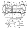
- the diaphragm pump includes an elongate body 11 assembled from a plurality of metal casings and defining a central drive housing 12 positioned between similar, but oppositely directed, pump housings 13.
- the pump housings 13 are each divided internally by a respective diagram 14 to produce a respective pump chamber 15 one wall of which is defined by the respective diaphragm 14 and a pressure chamber at the opposite side of the diaphragm.
- Each pump chamber 15 has an inlet 16 and an outlet 18 each containing a respective non-return valve 17, 19.
- the inlets 16 are in use connected to a supply of liquid to be pumped, for example paint, and the outlets 18 are connected to a demand system, for example a single output line supplying liquid pumped by the diaphragm pump to a spraying mechanism.
- the drive housing 12 defines a cylinder 21 within which a unitary piston assembly 22 is longitudinally reciprocable.
- the piston assembly 22 comprises an elongate spindle 23 having integrally formed thereon first and second spaced, parallel piston discs 24, 25.
- the discs 24, 25 carry seals 26 at their outer periphery, the seals 26 sealing the sliding interface of the discs 24, 25 and the cylinder 21.
- the spindle 23 projects, at its opposite axial ends, into the pump housings 13 and is connected at its opposite ends respectively to the diaphragms 14.
- Seals 27 seal the sliding interface of the spindle 23 and the pump housings such that the piston assembly 22 and the cylinder 21 define three annular chambers 28, 29, and 31, the chamber 28 being defined between the piston discs 24, 25 and thus being of constant volume, and the chambers 29 and 31 being defined between the disc 24 and the left-hand pump housing 13 and the disc 25 and the right-hand pump housing 13 respectively, and thus being of variable volume dependent upon the position of the piston assembly 22 axially within the cylinder 21.
- a pilot valve 32 comprising a housing 33 defining a cylinder 34 within which a shuttle 35 is longitudinally reciprocable.
- the shuttle 35 includes a central rod 36 having integral discs 37, 38 at its opposite axial ends respectively the discs 37, 38 being in sealed, sliding contact with the wall of the cylinder 34.
- the gap between the mutually presented faces of the discs 37, 38 is slightly greater than half the axial length of the cylinder 34 and at the mid-point of its length the housing 33 includes an inlet port 39 for receiving air under pressure to drive the diaphragm pump.
- first and second compressed air outlet ports 43, 44 Spaced from the end walls of the cylinder 34 by an amount slightly greater than the axial thickness of the discs 37, 38 are first and second compressed air outlet ports 43, 44 respectively. It will be recognised that by virtue of the length of the shuttle 35 in relation to the positioning of the ports 43, 44 then in the extreme left-hand position of the shuttle 35 the port 39 communicates with the port 43 whereas in the extreme right-hand position of the shuttle the port 39 communicates with the port 44.
- each pump housing 13 there is defined, at the opposite side of the respective diaphragm 14 from each pump chamber 15, a pressure chamber 45.
- a port 46 a in the wall of the chamber 45 a is connected through appropriate piping to the port 44 of the pilot valve 32 and a similar port 46 b in the wall of the chamber 45 b is similarly connected to the port 43 of the pilot valve 32.
- the cylinder 21 At the mid-point of its length the cylinder 21 has an exhaust port 47 connected to atmosphere.
- a port 48 in the wall of the chamber 21 adjacent the pump housing 13 a is connected by a pipe 49 to the pressure chamber 45 b and a port 51 in the wall of the cylinder 21 adjacent the pump housing 13 b is similarly connected through a pipe 52 to the pressure chamber 45 a .
- Two further ports 53, 54 are provided in the wall of the cylinder 21, the ports 53, 54 being spaced equally on opposite sides of the mid-point of the cylinder 21 and having a total spacing slightly less than the spacing between the discs 24, 25 of the piston assembly 22.
- the ports 53, 54 are connected respectively, by appropriate pipes, to the pilot ports 41, 42 of the pilot valve 32.
- the basic operation of the diaphragm pump is as follows.
- the port 39 of the pilot valve 32 is connected to a source of compressed air
- the inlets 16 a , 16 b are connected to a supply of liquid, for example by being connected through a common supply pipe to a reservoir
- the outlets 18 a , 18 b are connected to a demand system, for example a liquid spraying system.
- a demand system for example a liquid spraying system.
- compressed air is being supplied by way of the inlet port 39 and outlet port 43 of the valve 32 to the pressure chamber 45 b , and by virtue of the pipe 49 to the lefthand side of the piston disc 24.
- the pressure chamber 45 a and by virtue of the pipe 52 and the port 51, the right-hand side of the piston disc 25, are connected by way of the port 46 a , the appropriate pipe, the port 44, the pilot port 42, the port 54, and the exhaust port 47 to atmosphere.
- the effect of the non-return valve 17 b is to cause the liquid displaced by reducing the volume of the chamber 15 b to pass through the outlet 18 b , and similarly the non-return valve 19 a is preventing liquid being drawn back through the outlet 18 a and thus ensuring that liquid is drawn into the chamber 15 a through the inlet 16 a .
- the piston assembly 22 continues to move to the right until the piston disc 24 has moved beyond the port 53 whereupon the port 53 is exposed to the compressed air being applied to the left-hand side of the piston disc 24.
- port 53 is connected to port 41 of valve 32 and thus when port 53 is exposed to compressed air the air pressure is applied to the left-hand side of the shuttle 35, and since the right-hand side of the shuttle 35 is still connected to atmosphere by way of the port 42 the port 54 and the port 47 then the shuttle 35 is driven rapidly from its left-hand position (as shown in Figure 1) to its extreme right-hand position where the disc 35 abuts the right-hand end of the cylinder 34.
- the port 39 is connected to the port 44 and thus compressed air from the inlet port 39 of the valve 32 is now applied via the port 44 and the port 46 a to the pressure chamber 45 a , and by way of the pipe 52 and port 51 to the right-hand side of the piston disc 25.
- the shuttle 35 In moving to its extreme right-hand position the shuttle 35 provides a volume into which air under pressure in the chamber 45 b can expand so reducing its pressure.
- the piston assembly 22 and diaphragms 14 are driven in the opposite direction so that liquid is pumped from the pump chamber 15 a and drawn into the pump chamber 15 b .
- both pump chambers 15 supply the same demand system and at any given time one pump chamber is pumping while the other is performing an inlet stroke, there is nevertheless still a significant pressure fluctuation in the pump outlet line.
- the demand system ceases to require a supply from the pump then a point will be reached at which no liquid can be discharged through the outlet 18 a or 18 b and thus the pump will stall.
- the liquid In the stall condition the liquid is subjected to a pressure dependent upon the compressed air pressure and thus a significant surge of liquid can occur when the demand system next requires liquid.
- this surge can give rise to extremely undesirable spraying conditions occurring at the point when spraying recommences.
- the pressure fluctuations during normal operation can also give rise to disadvantageous spraying effects.
- FIGS 2, 3, and 4 illustrate a modification of the diaphragm pump arrangement described above which minimises the problems in a simple and convenient manner.
- each non-return valve 17 comprises a valve seat 61 received in screw threaded engagement in an inlet passage 62 of the respective pump housing.
- Each seat 61 has a frusto-conical seat surface 63 against which a ball 64, formed from steel, nylon, or other suitable material, abuts to close the valve.
- Inlet flow through the valve lifts the ball 54 away from the seat surface 63 and a transverse pin 65 in the passage 62 restricts movement of the ball 64 along the passage 62.
- the ball 64 is driven against the seat surface 63 by any attempt to induce a return flow and thus the valve acts as a normal non-return valve.
- the seat surface 63 is formed with three equi-angularly spaced grooves 66 of V-shaped cross-section which cannot be closed by the ball 64 and thus provide a controlled bleed through the non-return valve between the ball 64 and the seat surface 63. It will be recognised that when a pumping stroke is being performed a small proportion of the pump stroke output bleeds back through the grooves 66 into the inlet conduit 60, the remainder of the output of course exiting the pump chamber through the outlet passage 18.
- the controlled bleed through the inlet non-return valve ensures that the pump can never stall since even though a situation may arise in which no liquid can pass through the respective outlet passage 18, nevertheless liquid can be pumped through the bleed passages 66 and thus the pump will continue to operate at a relatively slow stroke rate.
- the controlled bleed therefore greatly minimises the disadvantageous surge effect which can occur with the conventional pump upon removal of a stall condition.
- the controlled bleed from each pump chamber acts to smooth the pressure fluctuations in the output of the pump thereby minimising, or in most cases removing, the need for a pressurised reservoir in the output line.
- each pump housing 13 could be drilled to provide a bleed passage between the upstream and downstream sides of the inlet non-return valve.
- an external bleed conduit could be provided with an interchangeable, or even a variable, restrictor so that the bleed effect can be adjusted to suit different applications.
- each pump chamber 15 is of the order of 1.1 litres and the operating air pressure can be between 10 and 90 psi, conveniently 45 psi.
- Each inlet non-return valve seat is of 12 mm diameter at its narrowest point and the three equi-angularly spaced bleed grooves 66 are each of 90° V-shaped cross-section and 1.5 mm deep at their apex.
- the structure of the diaphragm pump illustrated in Figure 5 differs from that of Figure 1 primarily in the provision of an additional port 61 in the wall of the cylinder 21, the port 61 being positioned axially midway between the ports 53 and 54, and thus being positioned axially of the cylinder 21 in the same position as the exhaust port 47.
- the spacing between the flanges 24 and 25 of the piston assembly 22 and the relative positioning of the ports 53 and 54 in the wall of the cylinder 21 also differs by comparison with the arrangement of Figure 1.
- the pilot valve differs significantly from the pilot valve of Figure 1 and so it, together with its connections to the ports of the diaphragm pump carry different reference numerals herein.
- the pilot valve 62 comprises a housing 63 defining a cylinder 64 within which a shuttle 65 is longitudinally reciprocable.
- the shuttle 65 includes a central rod 66 carrying four integral discs 67, 68, 69, 71.
- the discs are parallel to one another and have their outer periphery in sealed sliding engagement with the wall of the cylinder 64, there being 'O' ring seals at the sliding interface.
- the axially outermost discs 67, 71 are positioned axially inset from their respective ends of the rod 66 and the four discs are equi-distantly spaced along the rod 66.
- the spool 65 defines five axially spaced chambers 72-76 the central three of which are of fixed volume, and the opposite end ones of which are of variable volume dependent upon the position of the spool within the cylinder.
- the wall of the housing 63 is formed with a plurality of axially spaced ports.
- a first port 77 is positioned midway along the length of the cylinder 64 and is connected to a source of compressed air for providing power to the diaphragm pump.
- Six further ports 78, 79, 81, 82, 83, and 84 are spaced along the length of the cylinder and are connected by respective pipes (to be described in more detail hereinafter) to appropriate ports of the diaphragm pump.
- the port 78 is positioned at one axial end of the cylinder 64 and always communicates with the chamber 72 regardless of the position of the spool.
- the port 78 communicates, by way of a pipe 78 a with the port 53 of the body 12.
- the port 84 is at the opposite axial end of the cylinder 64 and always communicates with the chamber 76 regardless of the position of the spool 65.
- the port 84 is connected by way of a respective pipe 84 a to the port 54 of the body 12.
- the ports 81 and 82 of the housing 63 are axially spaced equi-distantly on opposite sides of the port 77 and are connected respectively to the ports 46 b and 46 a of the pump pressure chambers 45 b and 45 a by way of respective pipes 81 a and 82 a .
- the port 79 is positioned between the ports 78 and 81 and is closer to the port 81 than to the port 78.
- the port 83 is positioned between the ports 82 and 84 closer to the port 82 than to the port 84. Irrespective of the position of the spool 65 within the cylinder 64 the port 79 always communicates with the chamber 73 and the port 83 always communicates with the chamber 75.
- Pipes 79 a and 83 a connected to the ports 79 and 83 respectively communicate with a single pipe 61 a connected to the port 61 of the body 12.
- the ports 79, 83 are vented directly to atmosphere by way of pipe 61 a .
- Venting of the chamber 73 to atmosphere has no immediate effect since in the extreme left hand position of the spool 65 no other port communicates with the chamber 73.
- the port 82 is also in communication with the chamber 75 and thus the pressure chamber 45 a is also vented to atmosphere by way of the pipe 82 a and the chamber 75 and the chamber 31 of the body 12 is also vented to atmosphere by virtue of the port 51, the pipe 52 and the pump chamber 45 a .
- the extreme right hand position of the piston 22 places the port 54 in communication with the chamber 28 and thus the chamber 76 of the housing 63 is also vented to atmosphere by way of the pipe 84 a and the port 54.
- the chamber 72 of the housing 63 communicates with the chamber 29 of the body 12 by way of the port 78, the pipe 78 a , and the port 53 so that air under pressure is applied to the chamber 72. Since the chamber 72 is connected to the source of compressed air and the chamber 76 is vented to atmosphere, the spool 65 is driven rapidly to the right until it abuts the right hand end of the housing 63. In the extreme right hand position of the spool 65 the inlet port 77 still communicates with the chamber 74 but the disc 68 lies to the right of the port 81 and the disc 69 lies to the right of the port 82. Thus the port 81 is no longer connected to the source of compressed air and the port 82 is no longer vented to atmosphere.
- the port 82 is connected to the source of compressed air and the port 81 is vented to atmosphere by way of the chamber 73, the port 79, the pipe 79 a , the pipe 61 a , the port 61, the chamber 28, and the port 47.
- the pressure chamber 45 b and the chamber 29 of the body 12 are vented to atmosphere and compressed air is simultaneously applied to the pressure chamber 45 a and the chamber 31 thus driving the piston 22 and the diaphragms 14 to the left and causing a pumping stroke to be performed by the diaphragm 14 a expelling liquid from the chamber 15 a by way of the outlet 18 a .
- the chamber 15 b performs an induction stroke drawing liquid through the inlet 16 b .
- the spool 65 is thus driven rapidly to the left so that the pressure supply to the chamber 29 and the pressure chamber 45 b is re-established at the same time that the pressure chamber 45 a and the chamber 31 are vented to atmosphere so that a return stroke of the piston 22 occurs.
- the cycle of operation will repeat as described above provided that the port 77 receives a supply of compressed air and the port 47 is vented to atmosphere.
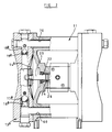
- the drive mechanism for the embodiment shown in Figure 6 differs from both of the previously described embodiments.
- the diaphragm pump includes an elongate, generally cylindrical body 90 defining a drive housing 91, and including a pair of pump housings 92 a , 92 b , one provided at each end of the body 90.
- the pump housings 92 a , 92 b are identical to those described with reference to Figures 1 to 4, and so will not be further described.
- the drive housing 91 defines a cylindrical chamber 93 within which a unitary piston 94 is reciprocable.
- the piston 94 comprises a spindle of diameter slightly smaller than the internal diameter of the chamber 93, and is provided with three annular recesses spaced along the length of the spindle such that the combination of the spindle and the drive housing 91 defines three chambers 95 a , 95 b , 95 c .
- the volume of each of the chambers 95 a , 95 b , 95 c is fixed, the only chambers whose volume can be varied being the pressure chambers 45 a , 45 b of the pump housings 92 a , 92 b .
- the piston 94 is provided with 'O' rings 96 located on the lands between the recesses 95 to provide sliding seals between the piston 94 and the drive housing 91.
- a pilot valve 100 is associated with the body 90, and comprises a generally cylindrical body 101 which defines a generally cylindrical chamber 102.
- a shuttle 103 is longitudinally reciprocable within the cylindrical chamber 102 and is in the form of a rod 104 provided with four axially spaced flanges 105.
- Each of the flanges 105 carries an 'O' ring 106 providing a sliding seal between the shuttle 103 and the body 101.
- the four flanges 105 divide the chamber 102 into five chambers 107 a , 107 b , 107 c , 107 d , 107 e .
- Pressurized air is supplied to the centre of the pilot valve 100 through an inlet 108.
- the length of the rod 104, and the spacing of the flanges 105 is such that throughout the movement of the shuttle the inlet 108 communicates with the centre chamber 107 c of the pilot valve 100.
- the centre chamber 107 c communicates with the left hand pressure chamber 45 a through an outlet 109 and a pipe 110.
- the pressurized air supplied to the left hand pressure chamber 45 a causes the piston 94 to move towards the left as shown in Figure 6, the right hand pressure chamber 45 b , which is the only other chamber of the elongate body 90 whose volume is not fixed, being exhausted to the atmosphere through pipes 111, 113 b , the fourth chamber 107 d of the pilot valve 100, and the central chamber 95 b of the drive housing 91.
- Pressurized air is also supplied to the first and third chambers 95 a , 95 c of the drive housing 91 through pipes 112 a , 112 b .
- the third chamber 95 c of the drive housing also communicates with the first, left hand, chamber 107 a of the pilot valve 100 through pipe 114, the pressurized air causing the shuttle 103 to move to the extreme right hand position within the chamber 102.
- the movement of the shuttle 103 results in the pressurized air being supplied to the right hand pressure chamber 45 b through pipe 111, the left hand pressure chamber 45 a being exhausted through pipes 110, 113 a , the second chamber 107 b of the pilot valve 100 and the central chamber 95 b of the drive housing 91. It will be understood that, as the piston 94 moves to the right, the communication between the third chamber 95 c of the drive housing 91 and the first chamber 107 a of the pilot valve 100 will be broken, the first chamber 107 a of the pilot valve 100 then being vented through the central chamber 95 b of the drive housing 91.
- the above cycle is repeated continuously until the pressurized air supply is turned off.
- the pump chambers include any of the bleed systems described above so that when there is no demand for pump output, paint supplied to the pump chamber can return back to the inlet side of the inlet valves, so preventing stalling.
- the shuttle 103 may move away from one of the ends of the chamber 102 of the pilot valve 100, for example due to slight vibrations of the pump, and take up a position in which the central chamber 107 c communicates with both pressure chambers 45 a , 45 b of the diaphragm pump, or one in which it does not communicate with either of the pressure chambers 45 a , 45 b . Which of these two alternatives occurs is dependant upon the spacing of the flanges 105 of the shuttle 103.
- the valve 120 comprises a valve element 121 which is arranged to engage with a valve seat 122 and incorporates a manual control button 123 such that manual movement of the button 123 moves the valve element 121 away from the valve seat 122, so that pressurized air is supplied to the first chamber 107 a of the pilot valve 100, resulting in the shuttle 103 being moved towards the right as shown in Figure 6. It will be understood that, as the first chamber 107 a of the pilot valve 100 is vented through pipe 114 and the centre chamber 95 b of the drive housing 91 at the time of operating the control button 123, it may be necessary to ensure some restriction in the pipe 114 in order to permit the pressure to rise sufficiently to cause the shuttle 103 to move towards the right.
- valve element 121 On removal of the manual loading from the control button 123, the valve element 121 is pushed into the valve seat 122 by the pressurized air. It will be understood that the device will also operate with the valve 120 alternatively connected to the fifth chamber 107 e of the pilot valve 100.
- the valve 120 shown in Figure 6 is also arranged to operate automatically when the pump is first started after its pressure source has been shut down.
- the valve 120 includes a spring 124 arranged to urge the valve element 121 away from the valve seat 122. Under normal operation, the pressure of the air being supplied to the valve is sufficient to drive the valve element 121 into the seat 122 against the force of the spring 124. However, when there is no air pressure supply, the pressure in the supply line is atmospheric pressure, and the spring 124 is able to open the valve 120.
- pressurized air is supplied to the first chamber 107 a of the pilot valve 100 through the open valve 120 causing the shuttle to move towards the right as shown in Figure 6, and the pump starts to operate. Pressurized air continues to be supplied to the first chamber 107 a until the pressure of the air in the valve 120 is great enough to overcome the force provided by the spring 124, and the close valve 120.
- the pump When the pump is operating to transfer paint from one location to another, rather than being used to supply paint to a paint spraying system, the pump preferably operates as quickly as possible, and so the air pressure supplied to the pilot valve 100 and hence to the pressure chambers 45 of the pump is preferably as large as possible.
- the paint is often required at a relatively low pressure, for example 10 psi.
- the shuttle 103 may not operate reliably at such low pressures thus prejudicing the operation of the pump.
- a pressure regulator 130 is provided in the air supply line 108 to the pilot valve 100 to control the pressure of the air supplied to the pump pressure chambers 45 by way of the pilot valve 100, so that the pressure in the pump chambers can be reduced while the pressure of the air supplied to the valve 120 and to the first and third chambers 95 a , 95 b of the body 91 remains at the supply pressure.
- the pressure regulator 130 is arranged so that the air pressure supplied to the pressure chambers 45 can be accurately adjusted and maintained so as to produce the optimum paint pressure for the paint spraying system.
- the element 94 of the pump has been referred to as a piston. It will be understood that, as the chambers 95 a , 95 b , and 95 c are of constant volume, the element 94 does not provide drive, the term piston being used in conformity with the descriptions of the other embodiments.
- Each of the above described diaphragm pumps includes a pair of pump chambers, the diaphragms of which are mechanically coupled by a common piston, the operation of the pump chambers being 180° out of phase.
- Such a bleed path may be provided by a restricted bore extending through the length of the piston and communicating with both of the pump chambers. It will be understood that the provision of such a bore through the piston will reduce both the pressure surge and the stall problems by bleeding fluid from one pumping chamber performing a pumping stroke to the other chamber performing its return stroke.
- the outlet valve in this case, is identical to the inlet valve described above with reference to Figures 2, 3 and 4, and so will not be further described, the inlet valve of such a pump being devoid of grooves.
- the outlet valves of the two pumping chambers communicate with a common outlet line and in normal operation liquid enters a pump chamber through the respective inlet valve when the piston and diaphragm are moved in such a manner as to increase the volume of the pump chamber. Since the two pumping chambers are operated 180° out of phase, it will be understood that as liquid enters one pump chamber, liquid is pumped out of the other pump chamber.
- the bleed at the outlet valves of the chambers enables pressure in the outlet line to bleed into the filling chamber whereby a pressure surge or pulse in the outlet line caused by liquid being expelled from one of the pump chambers is partly absorbed by bleeding into the other pump chamber which is filling.
- a further advantage of providing a bleed path through the outlet valve rather than through the inlet valve is that priming of the system is not adversely affected.
- the bleed path is provided through the inlet valve, there is a tendency for air bubbles in the inlet system during priming to remain in the system so preventing priming and normal operation, due to the back flow of liquid in the inlet pipe caused by liquid flowing through the bleed means.
- the bleed means is provided in the outlet valve, there is no back flow of liquid in the inlet pipe, and any air bubbles entering the inlet system are purged by being drawn through the pumping system.
- An external bleed path linking the pumping chambers and not involving the outlet valves could be provided if desired.
Landscapes
- Engineering & Computer Science (AREA)
- Mechanical Engineering (AREA)
- General Engineering & Computer Science (AREA)
- Reciprocating Pumps (AREA)
Applications Claiming Priority (4)
| Application Number | Priority Date | Filing Date | Title |
|---|---|---|---|
| GB919115973A GB9115973D0 (en) | 1991-07-24 | 1991-07-24 | Diaphragm pump |
| GB9115973 | 1991-07-24 | ||
| GB9120557 | 1991-09-27 | ||
| GB919120557A GB9120557D0 (en) | 1991-09-27 | 1991-09-27 | Diaphragm pump |
Publications (2)
| Publication Number | Publication Date |
|---|---|
| EP0524820A2 true EP0524820A2 (de) | 1993-01-27 |
| EP0524820A3 EP0524820A3 (en) | 1993-10-27 |
Family
ID=26299282
Family Applications (1)
| Application Number | Title | Priority Date | Filing Date |
|---|---|---|---|
| EP19920306727 Withdrawn EP0524820A3 (en) | 1991-07-24 | 1992-07-23 | Diaphragm pump |
Country Status (2)
| Country | Link |
|---|---|
| EP (1) | EP0524820A3 (de) |
| AU (1) | AU2057292A (de) |
Cited By (5)
| Publication number | Priority date | Publication date | Assignee | Title |
|---|---|---|---|---|
| NL1021048C2 (nl) * | 2002-07-11 | 2004-01-13 | Weir Netherlands B V | Zuigermembraanpomp. |
| WO2008101517A1 (en) * | 2007-02-22 | 2008-08-28 | Gardner Denver Thomas Gmbh | Multiple connection pump having noise reducing valve and bearing coupling |
| US10514027B2 (en) | 2013-12-13 | 2019-12-24 | Graco Minnesota Inc. | High-pressure to low-pressure changeover valve for a positive displacement pump |
| ES2774427A1 (es) * | 2019-01-21 | 2020-07-21 | Samoa Ind S A | Dispositivo de arranque a baja presion para bombas neumaticas |
| US11898548B2 (en) | 2014-06-16 | 2024-02-13 | Flow Control LLC | Diaphragm pump utilizing duckbill valves, multi-directional ports and flexible electrical connectivity |
Citations (6)
| Publication number | Priority date | Publication date | Assignee | Title |
|---|---|---|---|---|
| GB147228A (en) * | 1915-02-23 | 1921-07-21 | Vaile Kimes Company | Improvements in pumps |
| US3213878A (en) * | 1963-01-21 | 1965-10-26 | Acf Ind Inc | Fuel pump check valve |
| FR2029348A1 (de) * | 1969-01-20 | 1970-10-23 | Hunsinger Emile | |
| FR2163084A5 (de) * | 1971-11-25 | 1973-07-20 | Langen & Co | |
| DE3347747A1 (de) * | 1983-12-31 | 1985-07-18 | Dietmar 8500 Nürnberg Janus | Wasserpumpe fuer munddusche |
| US4936753A (en) * | 1988-06-03 | 1990-06-26 | The Aro Corporation | Diaphragm pump with interchangeable valves and manifolds |
-
1992
- 1992-07-23 EP EP19920306727 patent/EP0524820A3/en not_active Withdrawn
- 1992-07-24 AU AU20572/92A patent/AU2057292A/en not_active Abandoned
Patent Citations (6)
| Publication number | Priority date | Publication date | Assignee | Title |
|---|---|---|---|---|
| GB147228A (en) * | 1915-02-23 | 1921-07-21 | Vaile Kimes Company | Improvements in pumps |
| US3213878A (en) * | 1963-01-21 | 1965-10-26 | Acf Ind Inc | Fuel pump check valve |
| FR2029348A1 (de) * | 1969-01-20 | 1970-10-23 | Hunsinger Emile | |
| FR2163084A5 (de) * | 1971-11-25 | 1973-07-20 | Langen & Co | |
| DE3347747A1 (de) * | 1983-12-31 | 1985-07-18 | Dietmar 8500 Nürnberg Janus | Wasserpumpe fuer munddusche |
| US4936753A (en) * | 1988-06-03 | 1990-06-26 | The Aro Corporation | Diaphragm pump with interchangeable valves and manifolds |
Cited By (15)
| Publication number | Priority date | Publication date | Assignee | Title |
|---|---|---|---|---|
| DE10392934B4 (de) * | 2002-07-11 | 2015-02-05 | Weir Minerals Netherlands B.V. | Membranpumpe |
| US7201097B2 (en) | 2002-07-11 | 2007-04-10 | Weir Minerals Netherlands B.V. | Diaphragm pump |
| CN100381703C (zh) * | 2002-07-11 | 2008-04-16 | 韦尔矿物荷兰有限公司 | 隔膜泵 |
| AU2003257726B2 (en) * | 2002-07-11 | 2008-09-11 | Weir Minerals Netherlands B.V. | Diaphragm pump |
| WO2004007961A1 (en) * | 2002-07-11 | 2004-01-22 | Weir Netherlands B.V. | Diaphragm pump |
| NL1021048C2 (nl) * | 2002-07-11 | 2004-01-13 | Weir Netherlands B V | Zuigermembraanpomp. |
| WO2008101517A1 (en) * | 2007-02-22 | 2008-08-28 | Gardner Denver Thomas Gmbh | Multiple connection pump having noise reducing valve and bearing coupling |
| US10514027B2 (en) | 2013-12-13 | 2019-12-24 | Graco Minnesota Inc. | High-pressure to low-pressure changeover valve for a positive displacement pump |
| US11898548B2 (en) | 2014-06-16 | 2024-02-13 | Flow Control LLC | Diaphragm pump utilizing duckbill valves, multi-directional ports and flexible electrical connectivity |
| ES2774427A1 (es) * | 2019-01-21 | 2020-07-21 | Samoa Ind S A | Dispositivo de arranque a baja presion para bombas neumaticas |
| CN113316686A (zh) * | 2019-01-21 | 2021-08-27 | 萨摩亚工业股份公司 | 气动泵的低压启动装置 |
| JP2022517231A (ja) * | 2019-01-21 | 2022-03-07 | サモア インダストリアル, エセ.アー. | 空気圧ポンプ用の低圧始動装置 |
| EP3913222A4 (de) * | 2019-01-21 | 2023-03-01 | Samoa Industrial S.A. | Niederdruckstarter für pneumatische pumpen |
| WO2020152565A1 (es) * | 2019-01-21 | 2020-07-30 | Samoa Industrial, S.A. | Dispositivo de arranque a baja presión para bombas neumáticas |
| US11913442B2 (en) | 2019-01-21 | 2024-02-27 | Samoa Industrial, S.A. | Low pressure starter device for pneumatic pumps |
Also Published As
| Publication number | Publication date |
|---|---|
| EP0524820A3 (en) | 1993-10-27 |
| AU2057292A (en) | 1993-01-28 |
Similar Documents
| Publication | Publication Date | Title |
|---|---|---|
| US6644941B1 (en) | Apparatus and method for reducing ice formation in gas-driven motors | |
| US4029440A (en) | High pressure fluid intensifier and method | |
| US5092744A (en) | Intensifier | |
| US4854832A (en) | Mechanical shift, pneumatic assist pilot valve for diaphragm pump | |
| US7066353B2 (en) | Fluid powered additive injection system | |
| US4627794A (en) | Fluid pressure intensifier | |
| KR870008115A (ko) | 펌프조립체와 그 작동방법 | |
| US5273405A (en) | Fluid cushioning apparatus for hydraulic intensifier assembly | |
| CA2021863A1 (en) | Fluid sampling pump | |
| IL43965A (en) | Fluid pressure intensifier and method of alleviating potential pressure surges | |
| EP0524820A2 (de) | Membranpumpe | |
| WO1989010214A1 (en) | Apparatus for flushing of hydraulic pipe systems or the like | |
| GB1404691A (en) | Air operated hydraulic pump | |
| KR0136449B1 (ko) | 공압식 윤활 펌프 | |
| CA2466844C (en) | Diaphragm pump system | |
| CA1301546C (en) | Compact twin piston pump | |
| AU2002211187A1 (en) | A pump | |
| US3583832A (en) | Booster | |
| US3761204A (en) | Positive displacement boosters | |
| US6206649B1 (en) | Process and apparatus for pressurizing fluid and using them to perform work | |
| US4410304A (en) | Free piston pump | |
| EP1141545B1 (de) | Pumpe | |
| US8303265B2 (en) | Hydraulic pump | |
| CN219220905U (zh) | 一种直行程往复气缸 | |
| US5324173A (en) | High pressure intensifier |
Legal Events
| Date | Code | Title | Description |
|---|---|---|---|
| PUAI | Public reference made under article 153(3) epc to a published international application that has entered the european phase |
Free format text: ORIGINAL CODE: 0009012 |
|
| AK | Designated contracting states |
Kind code of ref document: A2 Designated state(s): AT BE DE DK FR GB IT NL SE |
|
| PUAL | Search report despatched |
Free format text: ORIGINAL CODE: 0009013 |
|
| AK | Designated contracting states |
Kind code of ref document: A3 Designated state(s): AT BE DE DK FR GB IT NL SE |
|
| 17P | Request for examination filed |
Effective date: 19940421 |
|
| 17Q | First examination report despatched |
Effective date: 19950124 |
|
| STAA | Information on the status of an ep patent application or granted ep patent |
Free format text: STATUS: THE APPLICATION IS DEEMED TO BE WITHDRAWN |
|
| 18D | Application deemed to be withdrawn |
Effective date: 19950804 |