EP0524377B1 - Akkumulatorenbatterie mit Kontrollvorrichtung am Zellenverbinder - Google Patents
Akkumulatorenbatterie mit Kontrollvorrichtung am Zellenverbinder Download PDFInfo
- Publication number
- EP0524377B1 EP0524377B1 EP92106566A EP92106566A EP0524377B1 EP 0524377 B1 EP0524377 B1 EP 0524377B1 EP 92106566 A EP92106566 A EP 92106566A EP 92106566 A EP92106566 A EP 92106566A EP 0524377 B1 EP0524377 B1 EP 0524377B1
- Authority
- EP
- European Patent Office
- Prior art keywords
- connector
- accumulator battery
- battery
- cell
- measuring resistor
- Prior art date
- Legal status (The legal status is an assumption and is not a legal conclusion. Google has not performed a legal analysis and makes no representation as to the accuracy of the status listed.)
- Expired - Lifetime
Links
Images
Classifications
-
- H—ELECTRICITY
- H01—ELECTRIC ELEMENTS
- H01M—PROCESSES OR MEANS, e.g. BATTERIES, FOR THE DIRECT CONVERSION OF CHEMICAL ENERGY INTO ELECTRICAL ENERGY
- H01M50/00—Constructional details or processes of manufacture of the non-active parts of electrochemical cells other than fuel cells, e.g. hybrid cells
- H01M50/50—Current conducting connections for cells or batteries
-
- G—PHYSICS
- G01—MEASURING; TESTING
- G01R—MEASURING ELECTRIC VARIABLES; MEASURING MAGNETIC VARIABLES
- G01R31/00—Arrangements for testing electric properties; Arrangements for locating electric faults; Arrangements for electrical testing characterised by what is being tested not provided for elsewhere
- G01R31/36—Arrangements for testing, measuring or monitoring the electrical condition of accumulators or electric batteries, e.g. capacity or state of charge [SoC]
- G01R31/378—Arrangements for testing, measuring or monitoring the electrical condition of accumulators or electric batteries, e.g. capacity or state of charge [SoC] specially adapted for the type of battery or accumulator
- G01R31/379—Arrangements for testing, measuring or monitoring the electrical condition of accumulators or electric batteries, e.g. capacity or state of charge [SoC] specially adapted for the type of battery or accumulator for lead-acid batteries
-
- G—PHYSICS
- G01—MEASURING; TESTING
- G01R—MEASURING ELECTRIC VARIABLES; MEASURING MAGNETIC VARIABLES
- G01R31/00—Arrangements for testing electric properties; Arrangements for locating electric faults; Arrangements for electrical testing characterised by what is being tested not provided for elsewhere
- G01R31/36—Arrangements for testing, measuring or monitoring the electrical condition of accumulators or electric batteries, e.g. capacity or state of charge [SoC]
- G01R31/382—Arrangements for monitoring battery or accumulator variables, e.g. SoC
- G01R31/3835—Arrangements for monitoring battery or accumulator variables, e.g. SoC involving only voltage measurements
-
- H—ELECTRICITY
- H01—ELECTRIC ELEMENTS
- H01M—PROCESSES OR MEANS, e.g. BATTERIES, FOR THE DIRECT CONVERSION OF CHEMICAL ENERGY INTO ELECTRICAL ENERGY
- H01M10/00—Secondary cells; Manufacture thereof
- H01M10/42—Methods or arrangements for servicing or maintenance of secondary cells or secondary half-cells
- H01M10/48—Accumulators combined with arrangements for measuring, testing or indicating the condition of cells, e.g. the level or density of the electrolyte
-
- H—ELECTRICITY
- H01—ELECTRIC ELEMENTS
- H01M—PROCESSES OR MEANS, e.g. BATTERIES, FOR THE DIRECT CONVERSION OF CHEMICAL ENERGY INTO ELECTRICAL ENERGY
- H01M50/00—Constructional details or processes of manufacture of the non-active parts of electrochemical cells other than fuel cells, e.g. hybrid cells
- H01M50/50—Current conducting connections for cells or batteries
- H01M50/569—Constructional details of current conducting connections for detecting conditions inside cells or batteries, e.g. details of voltage sensing terminals
-
- G—PHYSICS
- G01—MEASURING; TESTING
- G01R—MEASURING ELECTRIC VARIABLES; MEASURING MAGNETIC VARIABLES
- G01R31/00—Arrangements for testing electric properties; Arrangements for locating electric faults; Arrangements for electrical testing characterised by what is being tested not provided for elsewhere
- G01R31/36—Arrangements for testing, measuring or monitoring the electrical condition of accumulators or electric batteries, e.g. capacity or state of charge [SoC]
- G01R31/396—Acquisition or processing of data for testing or for monitoring individual cells or groups of cells within a battery
-
- Y—GENERAL TAGGING OF NEW TECHNOLOGICAL DEVELOPMENTS; GENERAL TAGGING OF CROSS-SECTIONAL TECHNOLOGIES SPANNING OVER SEVERAL SECTIONS OF THE IPC; TECHNICAL SUBJECTS COVERED BY FORMER USPC CROSS-REFERENCE ART COLLECTIONS [XRACs] AND DIGESTS
- Y02—TECHNOLOGIES OR APPLICATIONS FOR MITIGATION OR ADAPTATION AGAINST CLIMATE CHANGE
- Y02E—REDUCTION OF GREENHOUSE GAS [GHG] EMISSIONS, RELATED TO ENERGY GENERATION, TRANSMISSION OR DISTRIBUTION
- Y02E60/00—Enabling technologies; Technologies with a potential or indirect contribution to GHG emissions mitigation
- Y02E60/10—Energy storage using batteries
Definitions
- the invention relates to an accumulator battery, the cells of which are electrically connected on the top of the housing by cell connectors attached to the cell poles, the cell connectors being provided with a measuring resistor and connections for measuring devices for monitoring the operating state of the battery.
- a preferred field of application of the invention is lead accumulators, which are subject to uninterrupted strong cycle loads, such as in electrical traction.
- accumulators Under mild conditions, accumulators show a characteristic temporal course of the charging current and the discharging current, with which certain values of the voltage, the temperature and, if applicable, the pressure correspond at all times.
- monitoring the charge level is therefore particularly important. This can be assessed by measuring the charging current and the discharging current with a measuring resistor.
- the measuring resistor can z. B. in the charger or in the negative lead of the connection cable. Since he needs measuring lines to the battery and to an evaluation device, which may multiply by additional measuring lines to a temperature sensor, the result is a measuring device that is unwieldy and also annoying during maintenance or cleaning work.
- the measuring resistor forms a central section of a cell connector with elastically deformable ends, with measuring lines leading out of the plastic-coated measuring resistor and connecting it to the evaluation device.
- the invention is based on the object, starting from the possibility of a direct arrangement of the measuring resistor on the accumulator, of specifying an improved battery construction and at the same time making more information available with the measuring device.
- the core of the invention is then a measuring resistor for detecting the operating parameters mentioned at the beginning in the form of a cell connector, at least an integral section of this cell connector, which, like conventional embodiments of connectors, is a piece of metal that is rigid over its entire length. It is screwed with its ends onto the opposite poles of two neighboring cells.
- the preferred material of the connector according to the invention is copper.
- Constantan an alloy of 40% Ni and 60% Cu can preferably be used because its conductivity has a very low temperature coefficient. This metrological advantage is offset by the disadvantage of an increased line resistance. Regardless of the choice of connector material, the measuring resistance can be adapted to the requirements across the cross-section of the connector.
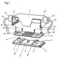
- Figure 1 shows the construction of the cell connector in elevation.
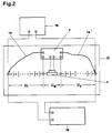
- Figure 2 shows the connection of the connector on a battery.
- the connector 1 made of copper and with a defined cross section is screwed over the surface of a battery housing by means of space-saving Allen screws 2, 3 onto the - not visible - opposite poles of two neighboring cells.
- the poles are at a normal distance apart.
- the Allen screws are preferably located in the elongated holes (not visible) of the connector.
- a short distance above the connector and parallel to it is a printed circuit board 7 with electronic components 6 and is mounted on insulating supports 8, 8 'and on a sensor 9 for measuring the temperature of the connector.
- the connector according to the invention is completed by a protective cover 11.
- locking connections are provided via snap edges 12, 12 'or the like.
- cover From the cover lead out via screw sockets 13, 13 'releasably attached, movable cables or data transmission lines 14, 14', which are connected to the end poles of the battery (not shown).
- the connection of the cable to the board is done by means of contacts 15, 15 ', which are non-positively connected to the cover.
- the electronic components on the board include semiconductor chips with electronic circuits, resistors, diodes and the like.
- the connector according to the invention thus has an electronic evaluation circuit which makes it possible to record and also store the time profiles of charge and discharge currents, the voltage and the temperature in accordance with the measurement voltage across the voltage tap on the connector; the connector according to the invention can therefore be referred to as an "intelligent connector".
- the connector 1 is preferably positioned on the accumulator battery 17 in such a way that there are the same number of cells to the left and right of it, the circuit virtually forms a "battery scale".
- the electronics on the circuit board 7 register in this case, in addition to the measuring voltage U M at the connector and the thermal voltage of the temperature sensor 9, two partial battery voltages U 1 and U 2 of the same size. Inequality of these voltages indicates a defective cell.
- the detected data arrive frequency-modulated to the battery end poles and from there on via the energy cable to the evaluation device in the charger 18.
- the switching electronics on the board is also supplied with the necessary energy .
- a consumer is designated.
- the amount of current can in particular be measured via the measuring resistor; the connector temperature via the temperature sensor; the potential position of the battery center relative to the potentials of the end poles when the battery is loaded; the battery voltage; the unloading or loading time.
- the electronics of the connector send control signals to the charger.
- the evaluation device in the charger takes over the integration of the amount of electricity via a discharge and charge, the determination of the charge factor, the determination of the number of cycles and the level of the average discharge current.
- the actual capacity of the battery can be determined by comparing the amount of current withdrawn and the battery voltage, taking into account the battery temperature and the discharge current.
- Defective cells are identified by comparing the partial voltages of the two battery halves during the discharge load. By evaluating the temperature, the charging factor, the deep discharge, the rest voltage and the actual capacity, stress conditions of the battery can be identified, such as excessive temperatures, excessive overcharging, deep discharges, long periods in the discharged state and a drop in the acid level.
Landscapes
- Chemical & Material Sciences (AREA)
- Chemical Kinetics & Catalysis (AREA)
- Electrochemistry (AREA)
- General Chemical & Material Sciences (AREA)
- Engineering & Computer Science (AREA)
- Manufacturing & Machinery (AREA)
- Physics & Mathematics (AREA)
- General Physics & Mathematics (AREA)
- Secondary Cells (AREA)
- Charge And Discharge Circuits For Batteries Or The Like (AREA)
Description
- Die Erfindung betrifft eine Akkumulatorenbatterie, deren Zellen auf der Oberseite des Gehäuses durch an den Zellenpolen angebrachte Zellenverbinder elektrisch verbunden sind, wobei die Zellenverbinder zur Überwachung des Betriebszustandes der Batterie mit einem Meßwiderstand und Anschlüssen für Meßeinrichtungen versehen sind. Vorzugsweises Anwendungsgebiet der Erfindung sind Bleiakkumulatoren, die ununterbrochenen starken Zyklenbelastungen unterliegen wie etwa in der Elektrotraktion.
- Unter schonenden Bedingungen zeigen Akkumulatoren einen charakteristischen zeitlichen Verlauf des Ladestromes und des Entladestromes, mit denen zu jedem Zeitpunkt bestimmte Werte der Spannung, der Temperatur und gegebenenfalls des Drucks korrespondieren. Aus den genannten Betriebsparametern ergibt sich ein "Benutzungsprofil" über der Zeit, welches typenspezifisch ist. Akkumulatorenzellen und -batterien verfügen auf diese Weise über eine Kennung, die eine Typenidentifizierung ermöglicht und es vor allem gestattet, das Ladeverfahen dem jeweiligen Batterietyp individuell anzupassen.
- Bei starker Beanspruchung der Batterie durch einen Verbraucher ist das Benutzungsprofil ihrer Betriebsparameter erheblich verzerrt, so daß deren ständige Kontrolle besonders wichtig wird, um das Ladegerät entsprechend dem aktuellen Betriebszustand zu steuern. Dies geschieht beispielsweise während des Einsatzes von Bleibatterien als Energiespeicher in Flurförderzeugen (Gabelstapler etc.). Dabei spielen allein vor dem Hintergrund der Fuhrparkorganisation Fragen nach der Auslastung der Batterien, ihrer momentanen Leistungsfähigkeit, dem Stand der Istkapazität oder nach den Einsatzbedingungen (Tiefentladung, hohe Temperaturen) eine entscheidende Rolle.
- Für einen optimalen Betrieb des Akkumulators ist daher vor allem die Überwachung des Ladezustandes notwendig. Man kann diesen bewerten, indem man den Ladestrom und den Entladestrom mit einem Meßwiderstand mißt. Der Meßwiderstand kann sich z. B. im Ladegerät oder in der Minusleitung des Anschlußkabels befinden. Da er Meßleitungen zur Batterie und zu einer Auswertungseinrichtung benötigt, die sich gegebenenfalls um weitere Meßleitungen zu einem Temperaturfühler vermehren, ergibt sich eine Meßeinrichtung, die unhandlich und bei Wartungs- oder Reinigungsarbeiten zudem störend ist.
- Bei einem bekannten mehrzelligen Akkumulator gemäß DE-OS 36 28 600 bildet der Meßwiderstand ein mittleres Teilstück eines Zellenverbinders mit elastisch verformbaren Enden, wobei Meßleitungen aus dem kunststoffummantelten Meßwiderstand herausführen und ihn mit der Auswertungseinrichtung verbinden.
- Der Erfindung liegt die Aufgabe zugrunde, von der Möglichkeit einer unmittelbaren Anordnung des Meßwiderstandes am Akkumulator ausgehend eine in diesem Sinne verbesserte Batteriekonstruktion anzugeben und mit der Meßeinrichtung zugleich mehr Informationen verfügbar zu machen.
- Die Aufgabe wird durch eine Akkumulatorenbatterie gelöst, wie sie im Patentanspruch 1 definiert ist.
- Kern der Erfindung ist danach ein Meßwiderstand zum Erfassen der eingangs erwähnten Betriebsparameter in Gestalt eines Zellenverbinders, zumindest eines integralen Teilabschnitts dieses Zellenverbinders, welcher wie gewöhnliche Ausführungsformen von Verbindern ein über seine volle Länge starres Metallstück ist. Es wird wie jene mit den Enden auf die entgegengesetzten Pole zweier benachbarter Zellen aufgeschraubt.
- Das vorzugsweise Material des Verbinders gemäß der Erfindung ist Kupfer. Vorzugsweise kann Konstantan, eine Legierung aus 40 % Ni und 60 % Cu verwendet werden, weil deren Leitvermögen einen sehr geringen Temperaturkoeffizienten aufweist. Diesem meßtechnischen Vorteil steht allerdings der Nachteil eines vergrößerten Leitungswiderstandes gegenüber. Unabhängig von der Wahl des Verbindermaterials kann der Meßwiderstand über den Querschnitt des Verbinders den Erfordernissen angepaßt werden.
- Anhand zweier Figuren wird der Gegenstand der Erfindung näher erläutert.
- Figur 1 zeigt die Konstruktion des Zellenverbinders in einem Aufriß.
- Figur 2 zeigt die Verschaltung des Verbinders auf einer Batterie.
- Nach Figur 1 ist der Verbinder 1 aus Kupfer und mit definiertem Querschnitt über der Oberfläche eines Batteriegehäuses mittels platzsparender Imbusschrauben 2,3 auf die - nicht sichtbaren - Gegenpole zweier benachbarter Zellen aufgeschraubt. Die Pole stehen in einem Normalabstand auseinander. Um dennoch Einbautoleranzen auszugleichen, sitzen die Imbusschrauben vorzugsweise in Langlöchern (nicht sichtbar) des Verbinders.
- Mit 4 sind Dichtelemente und mit 5 Kunststoffumspritzungen angedeutet, welche den Verbinder gegebenenfalls vollständig umhüllen und ihn säuredicht verkapseln.
- In geringem Abstand oberhalb des Verbinders und parallel zu diesem ist eine mit elektronischen Bausteinen 6 besetzte Platine 7 angeordnet und auf Isolierstützen 8, 8′ sowie auf einem Fühler 9 zur Messung der Temperatur des Verbinders gelagert. Zwei Schrauben 10, 10′ dienen zur Befestigung der Platine am Verbinder und zum Abgriff der Meßspannung.
- Nach der Montage der Platine wird der Verbinder gemäß Erfindung durch einen schützenden Deckel 11 komplettiert. Zu seiner Befestigung sind Rastverbindungen über Schnappkanten 12, 12′ oder dergl. vorgesehen. Aus dem Deckel sind über Schraubbuchsen 13, 13′ lösbar befestigte, bewegliche Kabel bzw. Datenübertragungsleitungen 14, 14′ herausgeführt, die mit den Endpolen der Batterie (nicht dargestellt) verbunden werden. Der Anschluß der Kabel an die Platine erfolgt mittels Kontakten 15, 15′, die kraftschlüssig mit dem Deckel verbunden sind. Beim Einrasten des Deckels werden die Kontakte (siehe Pfeile) in die Steckerbuchsen 16, 16′ auf der Platine eingeschoben.
- Die elektronischen Bausteine auf der Platine beinhalten Halbleiterchips mit elektronischen Schaltkreisen, Widerstände, Dioden und dergleichen. Der Verbinder gemäß Erfindung verfügt damit über eine elektronische Auswertungsschaltung, die es gestattet, die zeitlichen Verläufe von Lade- und Entladeströmen, der Spannung und der Temperatur nach Maßgabe der Meßspannung über dem Spannungsabgriff am Verbinder zu erfassen und auch zu speichern; der erfindungsgemäße Verbinder kann daher als "intelligenter Verbinder" bezeichnet werden.
- Gemäß dem Schaltungsschema in Figur 2 ist der Verbinder 1 auf der Akkumulatorenbatterie 17 vorzugsweise so positioniert, daß sich links und rechts von ihm gleichviele Zellen befinden, die Schaltung quasi eine "Batteriewaage" bildet. Vorausgesetzt, daß keine der Zellen fehlerhaft ist, registriert die Elektronik auf der Platine 7 in diesem Fall außer der Meßspannung UM am Verbinder und der Thermospannung des Temperaturmeßfühlers 9 zwei Batterie-Teilspannungen U₁ und U₂ von gleicher Größe. Ungleichheit dieser Spannungen deutet auf eine defekte Zelle hin.
- Über die äußeren Leitungen 14, 14′ der Platine gelangen die erfaßten Daten frequenzmoduliert zu den Batterieendpolen und von dort weiter über das Energiekabel zur Auswertungseinrichtung im Ladegerät 18. Über die Leitungen 14, 14′ wird die Schaltelektronik auf der Platine zugleich mit der notwendigen Energie versorgt. Mit 19 ist ein Verbraucher bezeichnet.
- Mit dem intelligenten Verbinder können insbesonders gemessen werden die Strommenge über den Meßwiderstand; die Verbindertemperatur über den Temperaturmeßfühler; die Potentiallage der Batteriemitte relativ zu den Potentialen der Endpole bei Belastung der Batterie; die Batteriespannung; die Entlade- oder Ladezeit. Zugleich gibt die Elektronik des Verbinders Steuersignale an das Ladegerät ab.
- Die Auswertungseinrichtung im Ladegerät übernimmt die Integration der Strommenge über eine Entladung und Ladung, die Bestimmung des Ladefaktors, die Ermittlung der Zyklenzahl und der Höhe des mittleren Entladestromes. Durch Vergleich der entnommenen Strommenge und der Batteriespannung unter Berücksichtigung der Batterietemperatur und des Entladestromes kann die Istkapazität der Batterie ermittelt werden.
- Durch Vergleich der Teilspannungen der beiden Batteriehälften während der Entladebelastung werden fehlerhafte Zellen erkannt. Durch die Auswertung der Temperatur, des Ladefaktors, der Tiefentladung, der Ruhespannung und der Istkapazität werden Streßbedingungen der Batterie erkennbar, wie zu hohe Temperaturen, starke Überladung, Tiefentladungen, lange Perioden im entladenen Zustand und Absinken des Säurespiegels.
Claims (5)
- Akkumulatorenbatterie, deren Zellen auf der Oberseite des Gehäuses durch an den Zellenpolen angebrachte Zellenverbinder elektrisch verbunden sind, wobei die Zellenverbinder (1) zur Überwachung des Betriebszustandes der Batterie mit einem Meßwiderstand und Anschlüssen für Meßeinrichtungen versehen sind, dadurch gekennzeichnet, daß der Meßwiderstand ein mittlerer Teilabschnitt eines über seine volle Länge starren Zellenverbinders (1) ist und daß dieser Zellenverbinder eine elektronische Auswertungsschaltung (6) besitzt, die es gestattet, die zeitlichen Verläufe von Lade- und Entladeströmen, der Spannungen und der Temperatur zu erfassen, zu bewerten und zu speichern und die mit zwei beweglichen äußeren Leitungen (14, 14′) an die Endpole der Batterie anschließbar ist.
- Akkumulatorenbatterie nach Anspruch 1, dadurch gekennzeichnet, daß die elektronische Auswertungsschaltung im Abstand oberhalb des Verbinders auf einer Platine (7) angeordnet ist und daß die Platine am Verbinder mittels Schrauben (10, 10′) befestigt ist, zwischen denen die über dem Meßwiderstand liegende Spannung abgreifbar ist.
- Akkumulatorenbatterie nach Anspruch 2, dadurch gekennzeichnet, daß an dem den Meßwiderstand bildenden Verbinderabschnitt ein Temperaturfühler (9) vorhanden ist.
- Akkumulatorenbatterie nach einem der Ansprüche 1 bis 3, dadurch gekennzeichnet, daß die beweglichen äußeren Leitungen mittels Steckverbindungen (15, 16) (15′, 16′) mit der Platine kontaktierbar sind.
- Akkumulatorenbatterie nach einem der Ansprüche 1 bis 4, dadurch gekennzeichnet, daß der Verbinder mitsamt zugehöriger Elektronik in einen Schutzdeckel 11 gekapselt ist.
Applications Claiming Priority (2)
| Application Number | Priority Date | Filing Date | Title |
|---|---|---|---|
| DE4123361A DE4123361C2 (de) | 1991-07-15 | 1991-07-15 | Akkumulatorenbatterie |
| DE4123361 | 1991-07-15 |
Publications (2)
| Publication Number | Publication Date |
|---|---|
| EP0524377A1 EP0524377A1 (de) | 1993-01-27 |
| EP0524377B1 true EP0524377B1 (de) | 1995-12-13 |
Family
ID=6436157
Family Applications (1)
| Application Number | Title | Priority Date | Filing Date |
|---|---|---|---|
| EP92106566A Expired - Lifetime EP0524377B1 (de) | 1991-07-15 | 1992-04-16 | Akkumulatorenbatterie mit Kontrollvorrichtung am Zellenverbinder |
Country Status (3)
| Country | Link |
|---|---|
| EP (1) | EP0524377B1 (de) |
| AT (1) | ATE131661T1 (de) |
| DE (2) | DE4123361C2 (de) |
Cited By (1)
| Publication number | Priority date | Publication date | Assignee | Title |
|---|---|---|---|---|
| DE102014200343A1 (de) | 2014-01-10 | 2015-07-16 | Robert Bosch Gmbh | Verfahren zum Ermitteln eines erhöhten Widerstands eines Zellverbinders |
Families Citing this family (19)
| Publication number | Priority date | Publication date | Assignee | Title |
|---|---|---|---|---|
| AU4506693A (en) * | 1992-06-29 | 1994-01-24 | Technology Partnership Limited, The | Integrated battery management systems |
| FR2706083A1 (fr) * | 1993-06-02 | 1994-12-09 | Texas Instruments France | Perfectionnements concernant des ensembles formant unités de batteries. |
| FR2748608B1 (fr) * | 1996-05-10 | 1998-06-12 | Accumulateurs Fixes | Systeme electronique pour batterie bipolaire et carte pour ce systeme |
| DE19834740C2 (de) * | 1998-08-01 | 2003-03-13 | Iq Battery Res & Dev Gmbh | Kraftfahrzeugbatterie mit integrierter Überwachungsvorrichtung und Verfahren zur Überwachung einer Kraftfahrzeugbatterie |
| AU2002222264A1 (en) * | 2000-12-26 | 2002-07-08 | Intelligent Battery Technology Limited | Storage battery with integrated detecton and indicating means |
| DE10134143A1 (de) * | 2001-07-13 | 2003-01-30 | Daimler Chrysler Ag | System zur Verschaltung von Schwachstromkomponenten mit Zellen in Hochleitstungsstromquellen |
| US20030082440A1 (en) * | 2001-10-29 | 2003-05-01 | Johnson Controls Technology Company | Battery system |
| FR2832856B1 (fr) * | 2001-11-28 | 2005-05-20 | Atp | Dispositif de batterie 24 volts |
| DE10214368B4 (de) * | 2002-03-30 | 2007-09-13 | Robert Bosch Gmbh | Energiespeichermodul und dessen Verwendung für ein Elektrogerät |
| EP1648048A3 (de) * | 2004-08-13 | 2009-04-22 | Ing. Büro M. Kyburz AG | Verfahren zum Optimieren der Lebensdauer von Traktionsbatterien |
| DE102005021959A1 (de) * | 2005-05-12 | 2006-11-23 | Leopold Kostal Gmbh & Co. Kg | Batteriestromsensor für ein Kraftfahrzeug |
| DE102006038050A1 (de) * | 2006-08-16 | 2008-02-21 | Iq Power Licensing Ag | Flüssigelektrolytbatterie mit Elektrolytfüllstandsmessung |
| AT511119B1 (de) * | 2011-03-09 | 2014-11-15 | Avl List Gmbh | Elektrischer energiespeicher |
| DE102011081124A1 (de) * | 2011-08-17 | 2013-02-21 | Sb Limotive Company Ltd. | Batteriemodul mit einer Batteriezustandserkennung (BZE) sowie ein Kraftfahrzeug mit einer Lithium Ionen Batterie |
| DE102012211701A1 (de) * | 2011-09-16 | 2013-03-21 | Robert Bosch Gmbh | Messwiderstand für Stromsensor und Stromsensoreinheit |
| DE102012204375A1 (de) | 2012-03-20 | 2013-09-26 | Robert Bosch Gmbh | Zugeinrichtung zum Verbinden von mindestens zwei Bauteilen eines elektrischen Energiespeichers, elektrischer Energiespeicher und Verfahren zum Verbinden von mindestens zwei Bauteilen eines elektrischen Energiespeichers |
| DE102012204591A1 (de) | 2012-03-22 | 2013-09-26 | Robert Bosch Gmbh | Verbindungseinrichtung zum Verbinden von elektrischen Bauelementen eines elektrischen Energiespeichers, elektrischer Energiespeicher und Verfahren zum Verbinden von elektrischen Bauelementen eines elektrischen Energiespeichers |
| DE102014017143B4 (de) * | 2014-11-20 | 2022-11-17 | Audi Ag | Energiespeicheranordnung, Kontaktierungselement und Verfahren zur Herstellung einer Energiespeicheranordnung |
| DE102018203578B4 (de) * | 2018-03-09 | 2022-09-29 | Volkswagen Aktiengesellschaft | Anordnung zur elektrischen Verbindung von Polterminals sowie Zellmodul oder Batterie mit einer derartigen Verbindungsanordnung (I) |
Family Cites Families (6)
| Publication number | Priority date | Publication date | Assignee | Title |
|---|---|---|---|---|
| US4237198A (en) * | 1979-09-06 | 1980-12-02 | Anderson Power Products, Inc. | Electrical device with bi-level battery state-of-charge indicator |
| US4431713A (en) * | 1982-04-15 | 1984-02-14 | Duracell Inc. | Method for adapting high voltage cells or batteries for lower volt rated applications |
| US4680527A (en) * | 1986-08-06 | 1987-07-14 | Motorola, Inc. | Electrical battery including apparatus for current sensing |
| DE3628600A1 (de) * | 1986-08-22 | 1988-02-25 | Deta Akkumulatoren | Akkumulator |
| WO1990001221A1 (en) * | 1988-07-27 | 1990-02-08 | Gnb Incorporated | Monitoring device for electric storage battery and configuration therefor |
| DE3907697C1 (en) * | 1989-03-10 | 1990-07-12 | Deta-Akkumulatorenwerk Gmbh, 3422 Bad Lauterberg, De | Drive battery |
-
1991
- 1991-07-15 DE DE4123361A patent/DE4123361C2/de not_active Expired - Lifetime
-
1992
- 1992-04-16 EP EP92106566A patent/EP0524377B1/de not_active Expired - Lifetime
- 1992-04-16 AT AT92106566T patent/ATE131661T1/de not_active IP Right Cessation
- 1992-04-16 DE DE59204656T patent/DE59204656D1/de not_active Expired - Fee Related
Cited By (2)
| Publication number | Priority date | Publication date | Assignee | Title |
|---|---|---|---|---|
| DE102014200343A1 (de) | 2014-01-10 | 2015-07-16 | Robert Bosch Gmbh | Verfahren zum Ermitteln eines erhöhten Widerstands eines Zellverbinders |
| DE102014200343B4 (de) | 2014-01-10 | 2021-08-12 | Robert Bosch Gmbh | Verfahren zum Ermitteln eines erhöhten Widerstands eines Zellverbinders, Verfahren zum Batteriemanagement, Computerprogramm, Batteriemanagementsystem, Batteriepack sowie Kraftfahrzeug mit einem Batteriepack |
Also Published As
| Publication number | Publication date |
|---|---|
| ATE131661T1 (de) | 1995-12-15 |
| DE4123361C2 (de) | 1998-04-23 |
| EP0524377A1 (de) | 1993-01-27 |
| DE4123361A1 (de) | 1993-01-21 |
| DE59204656D1 (de) | 1996-01-25 |
Similar Documents
| Publication | Publication Date | Title |
|---|---|---|
| EP0524377B1 (de) | Akkumulatorenbatterie mit Kontrollvorrichtung am Zellenverbinder | |
| DE19810746B4 (de) | Platine mit einer Schaltung zur Überwachung einer mehrzelligen Akkumulatorenbatterie | |
| EP2368304B1 (de) | Energiespeicheranordnung und verfahren zum betrieb einer derartigen anordnung | |
| EP0124739B1 (de) | Schaltungsanordnung zur kapazitätsabhängigen Nachladung eines Akkumulators | |
| EP2283537B1 (de) | Batterie mit batteriezellen und ladungsausgleichsvorrichtung und miteinander verschweissten polanschlüssen | |
| DE102018200039B4 (de) | Differenzspannungs-Messvorrichtung | |
| DE2850489C3 (de) | Vorrichtung zur Überwachung oder Steuerung des Betriebs wiederaufladbarer Akkumulatoren | |
| DE19545833B4 (de) | Batterie mit mehreren hintereinander geschalteten Einzelzellen | |
| DE102011104958A1 (de) | Batteriezellenintegrierte Messsensorleitung und Ausgleichswiderstand | |
| DE102005029096A1 (de) | Batteriezustandserkennung für Kfz-Akkumulatoren | |
| EP2704287A1 (de) | Zuschaltbare Ladungsausgleichsschaltung | |
| DE202009015040U1 (de) | Modul und System für eine elektrochemische Batteriezelle | |
| EP2208278B1 (de) | Ladegerät zur ladung mindestens eines wiederaufladbaren energiespeichers | |
| DE102009034409B4 (de) | Batterieüberwachungssystem | |
| EP2315292B1 (de) | Kontrollmodul zur Abdeckung einer Elektrochemischen Batteriezelle, und Batteriesystem mit einem solchen Modul | |
| EP0790690A2 (de) | Batteriemessmodul | |
| DE60204327T2 (de) | Anschlu element für ein elektrisches fahrzeug | |
| DE102020124737A1 (de) | Erfassungseinrichtung, Messanordnung, Batteriezelleneinheit, Kraftfahrzeug und Verfahren zum Erfassen einer Spannung | |
| DE3628600A1 (de) | Akkumulator | |
| EP2913882B1 (de) | Batterieüberwachungssystem, Batterieanordnung mit dem Batterieüberwachungssystem und Verfahren zum Betreiben der Batterieanordnung | |
| DE102008054532A1 (de) | Batteriemodul | |
| DE102015108428A1 (de) | Batterieeinheit für ein Flurförderzeug | |
| DE102012209177A1 (de) | Batteriesystem mit separat angeschlossener Bestimmungsschaltung sowie Batterie und Kraftfahrzeug mit Batteriesystem | |
| DE102022122165A1 (de) | Elektrische Schaltung zur Überwachung der jeweiligen Temperatur einer Mehrzahl von Ladekontakten eines Ladesteckverbinders | |
| DE19504629A1 (de) | Vorrichtung zur Ladung mehrzelliger Akkumulatorenbatterien |
Legal Events
| Date | Code | Title | Description |
|---|---|---|---|
| PUAI | Public reference made under article 153(3) epc to a published international application that has entered the european phase |
Free format text: ORIGINAL CODE: 0009012 |
|
| AK | Designated contracting states |
Kind code of ref document: A1 Designated state(s): AT DE FR GB SE |
|
| 17P | Request for examination filed |
Effective date: 19930126 |
|
| 17Q | First examination report despatched |
Effective date: 19940726 |
|
| GRAA | (expected) grant |
Free format text: ORIGINAL CODE: 0009210 |
|
| AK | Designated contracting states |
Kind code of ref document: B1 Designated state(s): AT DE FR GB SE |
|
| REF | Corresponds to: |
Ref document number: 131661 Country of ref document: AT Date of ref document: 19951215 Kind code of ref document: T |
|
| ET | Fr: translation filed | ||
| GBT | Gb: translation of ep patent filed (gb section 77(6)(a)/1977) |
Effective date: 19951214 |
|
| REF | Corresponds to: |
Ref document number: 59204656 Country of ref document: DE Date of ref document: 19960125 |
|
| PGFP | Annual fee paid to national office [announced via postgrant information from national office to epo] |
Ref country code: AT Payment date: 19960208 Year of fee payment: 5 |
|
| PLBE | No opposition filed within time limit |
Free format text: ORIGINAL CODE: 0009261 |
|
| STAA | Information on the status of an ep patent application or granted ep patent |
Free format text: STATUS: NO OPPOSITION FILED WITHIN TIME LIMIT |
|
| 26N | No opposition filed | ||
| REG | Reference to a national code |
Ref country code: FR Ref legal event code: TP |
|
| REG | Reference to a national code |
Ref country code: GB Ref legal event code: 732E |
|
| PG25 | Lapsed in a contracting state [announced via postgrant information from national office to epo] |
Ref country code: AT Effective date: 19970416 |
|
| PGFP | Annual fee paid to national office [announced via postgrant information from national office to epo] |
Ref country code: DE Payment date: 20000404 Year of fee payment: 9 |
|
| REG | Reference to a national code |
Ref country code: FR Ref legal event code: CD |
|
| REG | Reference to a national code |
Ref country code: GB Ref legal event code: IF02 |
|
| PG25 | Lapsed in a contracting state [announced via postgrant information from national office to epo] |
Ref country code: DE Free format text: LAPSE BECAUSE OF NON-PAYMENT OF DUE FEES Effective date: 20020201 |
|
| PGFP | Annual fee paid to national office [announced via postgrant information from national office to epo] |
Ref country code: GB Payment date: 20100325 Year of fee payment: 19 |
|
| PGFP | Annual fee paid to national office [announced via postgrant information from national office to epo] |
Ref country code: SE Payment date: 20110412 Year of fee payment: 20 Ref country code: FR Payment date: 20110426 Year of fee payment: 20 |
|
| GBPC | Gb: european patent ceased through non-payment of renewal fee |
Effective date: 20110416 |
|
| PG25 | Lapsed in a contracting state [announced via postgrant information from national office to epo] |
Ref country code: GB Free format text: LAPSE BECAUSE OF NON-PAYMENT OF DUE FEES Effective date: 20110416 |
|
| REG | Reference to a national code |
Ref country code: SE Ref legal event code: EUG |