EP0524062A1 - Method for making a load of rolls of compressible materials - Google Patents
Method for making a load of rolls of compressible materials Download PDFInfo
- Publication number
- EP0524062A1 EP0524062A1 EP92401975A EP92401975A EP0524062A1 EP 0524062 A1 EP0524062 A1 EP 0524062A1 EP 92401975 A EP92401975 A EP 92401975A EP 92401975 A EP92401975 A EP 92401975A EP 0524062 A1 EP0524062 A1 EP 0524062A1
- Authority
- EP
- European Patent Office
- Prior art keywords
- compression
- rollers
- modules
- stack
- station
- Prior art date
- Legal status (The legal status is an assumption and is not a legal conclusion. Google has not performed a legal analysis and makes no representation as to the accuracy of the status listed.)
- Granted
Links
Images
Classifications
-
- B—PERFORMING OPERATIONS; TRANSPORTING
- B65—CONVEYING; PACKING; STORING; HANDLING THIN OR FILAMENTARY MATERIAL
- B65B—MACHINES, APPARATUS OR DEVICES FOR, OR METHODS OF, PACKAGING ARTICLES OR MATERIALS; UNPACKING
- B65B13/00—Bundling articles
- B65B13/18—Details of, or auxiliary devices used in, bundling machines or bundling tools
- B65B13/20—Means for compressing or compacting bundles prior to bundling
Definitions
- the present invention relates to the packaging of compressible materials, and in particular insulating felts made of glass wool or other mineral wool, and is more particularly aimed at producing palletizable loads of reduced bulk facilitating the transport and storage of such products.
- the light fibrous insulating materials are generally packaged in the compressed state in the form of rolls closed by unitary packages of the paper belt or plastic envelope type, essentially based on polyethylene, heat-shrunk.
- these rollers are generally assembled in batches on pallets. In practice, the size of these must be compatible with the dimensions of the means of transport, trucks or more often, railway wagons. The latter also limit the total height of the palletized load, which must therefore ultimately comply with a fairly strict gauge in which a reduced number of rollers enters.
- the invention relates to a new solution for compacting a load of rollers of compressible material, and in particular of fibrous insulating material, or, which of course amounts to the same thing, for increasing the number of rollers per load, and this while preserving the quality of the material, taking particular care not to create permanent deformation remaining when the rollers are unpacked, even after a relatively long storage period, for example a few months.
- the method according to the invention consists in stacking rollers in several layers, the rollers being lying down, applying vertical compression by limiting the movements of the extreme rollers of each layer, removing this vertical compression to allow the stack to relax, finally set up links to control the stack to the dimensions obtained.
- the stack can be turned 90 so that the rollers end up standing.
- Temporary vertical compression can be very important, and in any case correspond to a compression rate much higher than the elastic compression limit of the material which, let us recall, is already very strongly compressed during the phase of constitution of the roller.
- the compression can for example temporarily reduce the height of the load to a height between 50% and 80% of the initial height, the duration of the compression phase being adjusted accordingly, and shorter as the temporary compression exerted is high.
- the pile must be maintained at the dimensions obtained after it is released; for this we can use a strapping machine that will set up two or three links, for example plastic.
- Another solution is to bandage with a plastic stretch film, the load being then protected from the weather and can therefore be stored in the open air.
- the stack of rollers is preferably limited to three layers, but several loads, at least two, can be superimposed before the step of placing the links, of course taking care that the axes of the rollers are well aligned to prevent the weight of the upper layers from degrading the lower layers.
- the vertical compression must not be completely compensated for by a displacement of the extreme rollers of each layer, so the latter must be retained, otherwise the compression would drive them aside. This can be done by pre-wrapping the stack of rollers before applying compression.
- Another solution is to surround all of the rollers constituting a layer, which has the advantage of providing modules, for example 4 to 6 rolls, prepackaged which can thus be sold in batches. In this case, the end faces of the rollers are not retained during compression, but on the condition of using a material which has a certain elasticity to surround the roller modules, a fact which poses in practice no problem.
- such belts made of thermoplastic material can contribute to joining the modules together before turning them over, this joining being obtained by heating the belts - for example by blowing hot air - during the release phase of the stack.
- the modules can also be joined together by means of glue strips or adhesive strips.
- the subject of the invention is also a device capable of implementing the method according to the invention, comprising a station for stacking the layers of rollers, a vertical compression station, possibly a rotation station at 90 from the stack, a link placement station and a transporter to move the stack from one station to another.
- the compression station can for example be constituted by a pressure plate suspended by means of a hoist above a conveyor belt used to introduce and evacuate the batteries. Such a compression station can be inserted into an existing packaging line without upsetting the latter.
- the compression station is constituted by a hydraulic table which lifts the load to come and press it against a fixed flat pressing plate, the table then replacing the transporter.
- the pressure plate is not strictly flat but has an additional thickness in its central part, constituting a sort of punch which increases locally and in particular directly below the rollers in the middle of each module. , the compressive force. This allows good alignment of the rollers of the same module which, when the belt is put in place, have a certain tendency to be arranged in an arc, the middle roller playing the role of keystone.
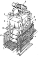
- FIG. 1 represents a perspective diagram of a compression station of a device according to the invention.
- the invention applies to rollers and more particularly to rolls of felts based on glass wool.
- These rolls are for example obtained by operating according to the methods described by patent applications FR-A-2,553,744, EP-A-238,393 or EP-A-294,320, or any other method capable of producing a winding with a compression as uniform as possible over the entire length of the wound felt strip, so as to lead to the formation of turns, all of the same thickness, including for the first wound that constitute the core of the roll and also its most brittle.
- a glass wool-based felt can withstand compression ratios of 4 or more, which means that the thickness of the wound strip is less than a quarter of the initial thickness, the initial thickness which is found when the strip is unrolled.
- all the rollers are produced with identical diameters, whatever the thickness of the strip, so as to maintain dimensions and a substantially constant weight, which simplifies their packaging. Thereafter and to fix the ideas, it will be done reference to a typical roller 400 mm to 410 mm in diameter and 1200 mm long, but it goes without saying that the method according to the invention can be applied to rolls of different diameters.
- the number of rollers per module or per load and half load can of course be modified and adapted to each particular case without departing from the scope of the invention.
- a first step the rolls, each wrapped in a film of heat-shrunk polyethylene, or more simply in kraft paper, are combined in modules of five, each module being surrounded.
- the rollers are laid side by side, arranged in the same alignment. This belt is under tension and therefore deforms the rollers which, from cylindrical, become ovoid, with their largest dimension along the vertical.
- the module has a height of the order of 445 mm and a length of 1495 - 1500 mm, which indicates a slight crushing on the sides.
- the modules are superimposed, as shown in Figure 1, where is shown a stack consisting of three modules 1, five rollers retained by a belt 2 retracted. Because this belt slightly compresses the rollers, the upper generatrices of the rollers of a given module - or respectively the lower generatrices - are not in fact strictly coplanar but define an arcuate curve, a roller - most often the central roller - playing a key role. This phenomenon can be annoying insofar as the more the loads carried out are parallelepipedic and the less will be their bulk. A suitable shape of the pressure plate according to the invention makes it possible to remedy this problem perfectly as will be shown later.
- the stack of three modules thus formed therefore has a height of between 1330 and 1340 mm. It is transported for example by a conveyor belt 3 to the compression station. This compression station is protected by lateral grids 4, the role of which is simply to ensure the safety of the personnel of the packaging line who may have to walk on the conveyor belt.
- the essential organ is a pressure plate 5, here constituted by a reinforced concrete block weighing 3 tonnes, supported by a metal frame made of commercial profiles.
- the pressure plate 5 is moved by means of a hoist 6 capable of moving the plate at slow or fast speed (for example at a speed of the order of 1 m / min at the time of compression and 4 m / min at the time approach and ascent cycles of the plateau).
- the hoist 6 is supported by a metal frame 7 which also plays a role in guiding the pressure plate 5 provided with a sliding guide system on the posts of the frame, and which moreover supports the conveyor belt 3 to compensate for its deformation due to compression forces.
- the assembly also comprises a safety device by locking the pressure plate 5 in the high position, this device being for example constituted by bars 8 on which the heels 9 abut associated with the pressure plate 5 thus preventing its descent.
- this device being for example constituted by bars 8 on which the heels 9 abut associated with the pressure plate 5 thus preventing its descent.
- these bars 8 are separated, by a connecting rod 10 controlled manually in the case shown here, but which can also be controlled in automatic operation by load presence detectors.
- the pressure plate 5 has in its central part, facing the rollers in the middle of the stack, an extra thickness forming a sort of punch, which makes it possible to bring the various modules flat.
- the pressure plate 5 is lowered and crushes the stack so as to reduce its height to a value comprised, for example, between 950 and 1000 mm.
- Such vertical compression is partially compensated by an increase in the length of the modules which, depending on the case, reaches 30 to 50 mm.
- Such compression of the rollers which is added to the compression of the felt produced during winding, is in itself perfectly unacceptable and would inevitably lead to significant degradation of the felt, with a loss of recovery in thickness, if it was maintained for a relatively long period of time. However, it has become apparent that such degradation does not occur if this period of time is short enough.
- this compression is maintained for a duration which is not less than 15 seconds nor more than 40 seconds and preferably between 20 and 30 seconds. If one chooses to compress the load even more, for example by means of a heavier pressure plate, this compression duration will preferably be slightly reduced. Otherwise, it may be lengthened, although this solution is generally not preferred since it leads to a slowing down of production rates.
- the stack is then evacuated and then rotated 90 ° by an appropriate rocking device, so as to arrange the rollers upright.
- Another identical stack is then formed and, by means of a gripping device, for example of the pliers type, the two stacks are placed one on the other on a pallet, ensuring that the rollers of the row are aligned with the lower rollers.
- the load thus formed is kept permanently in state by wrapping with a plastic stretch film. This wrapping makes it possible to compensate for a slightly too great possible loosening of the loads, without however compressing them more (the rollers expand due to a loosening, not a swelling, in other words the air evacuated between the rollers during of compression does does not re-enter the battery during the expansion phase).
- the invention makes it possible to significantly improve the filling coefficient of the means of transport (railway wagons or trucks), the loads being of a reduced bulk.
- the modules may not be glued but maintained by any binding.
- the stack can also be held before compression by wrapping, which then makes the belts of the modules unnecessary.
- the mobile pressure plate can be replaced by a fixed plate associated with a hydraulic table.
Abstract
Description
La présente invention est relative au conditionnement de matériaux compressibles, et notamment de feutres isolants en laine de verre ou autre laine minérale, et vise plus particulièrement la réalisation de charges palettisables d'encombrement réduit facilitant le transport et le stockage de tels produits.The present invention relates to the packaging of compressible materials, and in particular insulating felts made of glass wool or other mineral wool, and is more particularly aimed at producing palletizable loads of reduced bulk facilitating the transport and storage of such products.
Les matériaux isolants fibreux légers sont généralement conditionnés à l'état comprimé sous la forme de rouleaux fermés par des emballages unitaires du type ceinture de papier ou enveloppe en matière plastique, essentiellement à base de polyéthylène, rétractés à la chaleur. Pour diminuer le coût des opérations de transport, notamment lors des chargements et déchargements, et pour simplifier le stockage, ces rouleaux sont généralement assemblés par lots sur palettes. En pratique, la taille de celles-ci doit être compatible avec les dimensions des moyens de transport, camions ou le plus souvent, wagons de chemin de fer. Ces derniers limitent également la hauteur totale de la charge palettisée, qui doit donc finalement respecter un gabarit assez strict dans lequel entre un nombre réduit de rouleaux.The light fibrous insulating materials are generally packaged in the compressed state in the form of rolls closed by unitary packages of the paper belt or plastic envelope type, essentially based on polyethylene, heat-shrunk. To reduce the cost of transport operations, especially during loading and unloading, and to simplify storage, these rollers are generally assembled in batches on pallets. In practice, the size of these must be compatible with the dimensions of the means of transport, trucks or more often, railway wagons. The latter also limit the total height of the palletized load, which must therefore ultimately comply with a fairly strict gauge in which a reduced number of rollers enters.
D'autre part, et sauf à entourer la charge de panneaux rigides de façon à constituer des cages protectrices assurant la définition du volume alloué aux rouleaux - solution qui a évidemment pour défaut d'accroître considérablement le coût de la charge -, les rouleaux doivent obligatoirement être montés debout, de sorte que le poids des rouleaux constituant les couches supérieures agit perpendiculairement à la force radiale de compression exercée lors de la constitution du rouleau. Dans ces conditions, augmenter le nombre de rouleaux par charge palettisée ne semble être possible qu'en réduisant le diamètre des rouleaux, donc en augmentant le taux de compression lors de l'enroulement. Cette solution, déjà très largement mise en oeuvre, est toutefois réduite par la limite de compression élastique du matériau ; rappelons que la capacité isolante d'un matériau fibreux est fonction directement de son épaisseur et qu'il n'est donc pas question d'accepter une quelconque dégradation à ce niveau.On the other hand, and except to surround the load with rigid panels so as to constitute protective cages ensuring the definition of the volume allocated to the rollers - solution which obviously has the defect of considerably increasing the cost of the load - the rollers must must be mounted upright, so that the weight of the rollers constituting the upper layers acts perpendicular to the radial compression force exerted during the constitution of the roll. Under these conditions, increasing the number of rollers per palletized load only seems to be possible by reducing the diameter of the rollers, therefore by increasing the compression ratio during winding. This solution, already widely implemented, is however reduced by the elastic compression limit of the material; remember that the insulating capacity of a fibrous material is a direct function of its thickness and that there is therefore no question of accepting any degradation at this level.
Il a également été proposé dans la demande de brevet européen n° EP-A-275 473 de ceinturer un groupe de cinq ou neuf rouleaux à l'aide d'une feuille de matière plastique, de venir coiffer le groupe ainsi isolé au moyen d'un dispositif d'aspiration qui évacue une partie de l'air emprisonné entre les spires de feutre enroulées et entre les rouleaux. L'évacuation de ce volume d'air permet alors de rapprocher les rouleaux, la charge étant maintenue définitivement dans cet état réduit au moyen d'un banderolage. Un tel procédé implique toutefois une installation relativement complexe et surtout impose une seconde phase de banderolage dans le cas où les lots doivent être superposés.It has also been proposed in European patent application No. EP-A-275 473 to surround a group of five or nine rollers using a sheet of plastic material, to cap the group thus isolated by means of '' a suction device which evacuates part of the air trapped between the coiled felt turns and between the rollers. The evacuation of this volume of air then makes it possible to bring the rollers closer together, the load being permanently maintained in this reduced state by means of a wrapping. Such a process however involves a relatively complex installation and above all requires a second wrapping phase in the case where the batches have to be stacked.
L'invention vise une nouvelle solution pour compacter une charge de rouleaux en matériau compressible, et notamment en matériau fibreux isolant, ou, ce qui revient bien sûr au même, pour augmenter le nombre de rouleaux par charge, et ceci en préservant la qualité du matériau, en veillant notamment à ne pas créer de déformations permanentes subsistant lors du déballage des rouleaux, même après une durée de stockage relativement longue, par exemple de quelques mois.The invention relates to a new solution for compacting a load of rollers of compressible material, and in particular of fibrous insulating material, or, which of course amounts to the same thing, for increasing the number of rollers per load, and this while preserving the quality of the material, taking particular care not to create permanent deformation remaining when the rollers are unpacked, even after a relatively long storage period, for example a few months.
A cet effet, il est proposé un procédé consistant à réarranger des rouleaux par application temporaire d'une surcompression. Plus précisément, le procédé selon l'invention consiste à empiler des rouleaux selon plusieurs couches, les rouleaux étant couchés, appliquer une compression verticale en limitant les mouvements des rouleaux extrêmes de chaque couche, supprimer cette compression verticale pour laisser se relâcher la pile, enfin mettre en place des liens pour maîtriser la pile aux dimensions obtenues. En outre, avant de mettre en place ces liens, on peut tourner la pile à 90 de manière à ce que les rouleaux se retrouvent debouts.To this end, a method is proposed consisting in rearranging rollers by temporary application of a overcompression. More specifically, the method according to the invention consists in stacking rollers in several layers, the rollers being lying down, applying vertical compression by limiting the movements of the extreme rollers of each layer, removing this vertical compression to allow the stack to relax, finally set up links to control the stack to the dimensions obtained. In addition, before putting these links in place, the stack can be turned 90 so that the rollers end up standing.
La compression verticale temporaire peut être très importante, et en tout cas correspondre à un taux de compression bien supérieur à la limite de compression élastique du matériau qui, rappelons-le, est déjà très fortement comprimé lors de la phase de constitution du rouleau. La compression peut par exemple ramener temporairement la hauteur de la charge à une hauteur comprise entre 50% et 80% de la hauteur initiale, la durée de la phase de compression étant ajustée en conséquence, et d'autant plus courte que la compression temporaire exercée est élevée.Temporary vertical compression can be very important, and in any case correspond to a compression rate much higher than the elastic compression limit of the material which, let us recall, is already very strongly compressed during the phase of constitution of the roller. The compression can for example temporarily reduce the height of the load to a height between 50% and 80% of the initial height, the duration of the compression phase being adjusted accordingly, and shorter as the temporary compression exerted is high.
Dès que la compression est interrompue, les rouleaux reprennent une partie de leur épaisseur initiale, mais une partie seulement. Néanmoins, le gain d'épaisseur ne se traduit pas par une dégradation du matériau compressible. L'examen des rouleaux montre qu'en fait, cette diminution de la hauteur de la charge n'est pas due à une nouvelle compression de la charge, mais à un réarrangement des rouleaux, qui, d'une forme initialement cylindrique, passent à une forme plus parallélépipèdique, forme qui conduit à un empilement plus compact. De façon surprenante, il est apparu que cette forme parallélépipèdique ne nuit absolument pas à la qualité du produit final, et que le produit déballé ne garde aucune trace de son conditionnement.As soon as the compression is interrupted, the rollers resume part of their initial thickness, but only part. However, the gain in thickness does not translate into a degradation of the compressible material. Examination of the rollers shows that in fact this reduction in the height of the load is not due to a new compression of the load, but to a rearrangement of the rollers, which, from an initially cylindrical shape, pass to a more parallelepiped shape, a shape which leads to a more compact stacking. Surprisingly, it appeared that this parallelepiped shape does absolutely no harm to the quality of the final product, and that the unpacked product does not keep any trace of its packaging.
La pile doit être maintenue aux dimensions obtenues après qu'elle se soit relâchée ; pour cela on peut utiliser une cercleuse qui va mettre en place deux ou trois liens, par exemple en matière plastique. Une autre solution est de procéder à un banderolage avec un film étirable en matière plastique, la charge étant alors préservée des intempéries et pouvant de ce fait être stockée à l'air libre.The pile must be maintained at the dimensions obtained after it is released; for this we can use a strapping machine that will set up two or three links, for example plastic. Another solution is to bandage with a plastic stretch film, the load being then protected from the weather and can therefore be stored in the open air.
La pile de rouleaux est de préférence limitée à trois couches, mais plusieurs charges, deux à tout le moins, peuvent être superposées avant l'étape de mise en place des liens, en veillant bien sûr à ce que les axes des rouleaux soient bien alignés pour éviter que le poids des couches supérieures ne vienne à dégrader les couches inférieures.The stack of rollers is preferably limited to three layers, but several loads, at least two, can be superimposed before the step of placing the links, of course taking care that the axes of the rollers are well aligned to prevent the weight of the upper layers from degrading the lower layers.
La compression verticale ne doit pas être compensée totalement par un déplacement des rouleaux extrêmes de chaque couche, aussi ces derniers doivent-ils être retenus, sinon la compression les chasserait de côté. Pour ce faire, il peut être procédé à un prébanderolage de la pile de rouleaux avant l'application de la compression. Une autre solution est de ceinturer l'ensemble des rouleaux constituant une couche, ce qui présente l'avantage de fournir des modules, de par exemple 4 à 6 rouleaux, préemballés qui pourront ainsi être commercialisés par lot. Dans ce cas, les faces d'about des rouleaux ne sont pas retenues lors de la compression, mais à la condition d'utiliser un matériau qui présente une certaine élasticité pour ceinturer les modules de rouleaux, fait qui ne pose en pratique aucun problème. Par ailleurs, de telles ceintures en matière thermoplastique peuvent contribuer à solidariser entre eux les modules avant de les retourner, cette solidarisation étant obtenue en chauffant les ceintures - par exemple par un soufflage d'air chaud - pendant la phase de relâchement de la pile. Les modules peuvent également être solidarisés entre eux au moyen de bandes de colle ou de bandes adhésives.The vertical compression must not be completely compensated for by a displacement of the extreme rollers of each layer, so the latter must be retained, otherwise the compression would drive them aside. This can be done by pre-wrapping the stack of rollers before applying compression. Another solution is to surround all of the rollers constituting a layer, which has the advantage of providing modules, for example 4 to 6 rolls, prepackaged which can thus be sold in batches. In this case, the end faces of the rollers are not retained during compression, but on the condition of using a material which has a certain elasticity to surround the roller modules, a fact which poses in practice no problem. Furthermore, such belts made of thermoplastic material can contribute to joining the modules together before turning them over, this joining being obtained by heating the belts - for example by blowing hot air - during the release phase of the stack. The modules can also be joined together by means of glue strips or adhesive strips.
L'invention a également pour objet un dispositif apte à la mise en oeuvre du procédé selon l'invention, comportant un poste d'empilage des couches de rouleaux, un poste de compression verticale, éventuellement un poste de rotation à 90 de la pile, un poste de mise en place des liens et un transporteur pour déplacer la pile d'un poste à l'autre.The subject of the invention is also a device capable of implementing the method according to the invention, comprising a station for stacking the layers of rollers, a vertical compression station, possibly a rotation station at 90 from the stack, a link placement station and a transporter to move the stack from one station to another.
Le poste de compression peut être par exemple constitué par un plateau presseur suspendu au moyen d'un palan au-dessus d'un transporteur à bande servant à introduire et à évacuer les piles. Un tel poste de compression peut être inséré dans une ligne d'emballage existante sans bouleversement de celle-ci. Dans une autre variante de l'invention, le poste de compression est constitué par une table hydraulique qui soulève la charge pour venir la presser contre un plateau presseur plan fixe, la table se substituant alors au transporteur.The compression station can for example be constituted by a pressure plate suspended by means of a hoist above a conveyor belt used to introduce and evacuate the batteries. Such a compression station can be inserted into an existing packaging line without upsetting the latter. In another variant of the invention, the compression station is constituted by a hydraulic table which lifts the load to come and press it against a fixed flat pressing plate, the table then replacing the transporter.
Dans une variante plus particulièrement préférée de l'invention, le plateau presseur n'est pas rigoureusement plat mais comporte une surépaisseur dans sa partie centrale, constituant une sorte de poinçon qui accroît localement et notamment à l'aplomb des rouleaux du milieu de chaque module, la force de compression. Ceci permet un bon alignement des rouleaux d'un même module qui, lors de la mise en place de la ceinture, ont une certaine tendance à se disposer en arc, le rouleau du milieu jouant un rôle de clé de voûte.In a more particularly preferred variant of the invention, the pressure plate is not strictly flat but has an additional thickness in its central part, constituting a sort of punch which increases locally and in particular directly below the rollers in the middle of each module. , the compressive force. This allows good alignment of the rollers of the same module which, when the belt is put in place, have a certain tendency to be arranged in an arc, the middle roller playing the role of keystone.
D'autres détails et caractéristiques avantageuses de l'invention sont décrits ci-après en référence à la figure annexée 1 qui représente un schéma en perspective d'un poste de compression d'un dispositif selon l'invention.Other details and advantageous characteristics of the invention are described below with reference to the appended figure 1 which represents a perspective diagram of a compression station of a device according to the invention.
Comme déjà indiqué, l'invention s'applique à des rouleaux et plus particulièrement à des rouleaux de feutres à base de laine de verre. Ces rouleaux sont par exemple obtenus en opérant selon les procédés décrits par les demandes de brevet FR-A-2 553 744, EP-A-238 393 ou EP-A-294 320, ou tout autre procédé apte à produire un enroulement avec une compression aussi uniforme que possible sur toute la longueur de la bande de feutre enroulée, de façon à conduire à la formation de spires, toutes de la même épaisseur, y compris pour les premières enroulées qui constituent le coeur du rouleau et également sa partie la plus fragile.As already indicated, the invention applies to rollers and more particularly to rolls of felts based on glass wool. These rolls are for example obtained by operating according to the methods described by patent applications FR-A-2,553,744, EP-A-238,393 or EP-A-294,320, or any other method capable of producing a winding with a compression as uniform as possible over the entire length of the wound felt strip, so as to lead to the formation of turns, all of the same thickness, including for the first wound that constitute the core of the roll and also its most brittle.
Si les précautions adéquates sont prises au moment où la bande de feutre est enroulée sur elle-même, un feutre à base de laine de verre peut supporter des taux de compression de 4 ou plus, ce qui signifie que l'épaisseur de la bande enroulée est inférieure au quart de l'épaisseur initiale, épaisseur initiale qui est retrouvée lorsque la bande est déroulée. Généralement, tous les rouleaux sont produits avec des diamètres identiques, quelle que soit l'épaisseur de la bande, de manière à conserver des dimensions et un poids sensiblement constants, ce qui simplifie leur conditionnement. Par la suite et pour fixer les idées, il sera donc fait référence à un rouleau type de 400 mm à 410 mm de diamètre et de 1200 mm de long, mais il va de soi que le procédé selon l'invention peut être appliqué à des rouleaux de différents diamètres. De même, le nombre de rouleaux par module ou par charge et demi-charge peut bien sûr être modifié et adapté à chaque cas particulier sans sortir du cadre de l'invention.If proper precautions are taken when the felt strip is wound on itself, a glass wool-based felt can withstand compression ratios of 4 or more, which means that the thickness of the wound strip is less than a quarter of the initial thickness, the initial thickness which is found when the strip is unrolled. Generally, all the rollers are produced with identical diameters, whatever the thickness of the strip, so as to maintain dimensions and a substantially constant weight, which simplifies their packaging. Thereafter and to fix the ideas, it will be done reference to a typical roller 400 mm to 410 mm in diameter and 1200 mm long, but it goes without saying that the method according to the invention can be applied to rolls of different diameters. Likewise, the number of rollers per module or per load and half load can of course be modified and adapted to each particular case without departing from the scope of the invention.
Dans une première étape, les rouleaux enveloppés chacun dans un film de polyéthylène rétracté à la chaleur, ou plus simplement en papier kraft, sont associés par modules de cinq, chaque module étant ceinturé. Dans un module, les rouleaux sont couchés côte à côte, disposés dans le même alignement. Cette ceinture est sous tension et déforme donc les rouleaux qui, de cylindriques, deviennent ovoïdes, avec leur plus grande dimension selon la verticale. Typiquement, le module a une hauteur de l'ordre de 445 mm et une longueur de 1495 - 1500 mm, ce qui traduit un léger écrasement sur les côtés.In a first step, the rolls, each wrapped in a film of heat-shrunk polyethylene, or more simply in kraft paper, are combined in modules of five, each module being surrounded. In one module, the rollers are laid side by side, arranged in the same alignment. This belt is under tension and therefore deforms the rollers which, from cylindrical, become ovoid, with their largest dimension along the vertical. Typically, the module has a height of the order of 445 mm and a length of 1495 - 1500 mm, which indicates a slight crushing on the sides.
Dans une seconde étape, les modules sont superposés, ainsi que représenté en figure 1, où est schématisée une pile constituée de trois modules 1, de cinq rouleaux retenus par une ceinture 2 rétractée. Du fait que cette ceinture comprime légèrement les rouleaux, les génératrices supérieures des rouleaux d'un module donné - ou respectivement les génératrices inférieures - ne sont en fait pas rigoureusement coplanaires mais définissent une courbe arquée, un rouleau - le plus souvent le rouleau central - jouant un rôle de clé de voûte. Ce phénomène peut être gênant dans la mesure où plus les charges réalisées sont parallélépipèdiques et moindre sera leur encombrement. Une forme adaptée du plateau presseur selon l'invention permet de remédier parfaitement à ce problème comme il sera montré par la suite.In a second step, the modules are superimposed, as shown in Figure 1, where is shown a stack consisting of three modules 1, five rollers retained by a belt 2 retracted. Because this belt slightly compresses the rollers, the upper generatrices of the rollers of a given module - or respectively the lower generatrices - are not in fact strictly coplanar but define an arcuate curve, a roller - most often the central roller - playing a key role. This phenomenon can be annoying insofar as the more the loads carried out are parallelepipedic and the less will be their bulk. A suitable shape of the pressure plate according to the invention makes it possible to remedy this problem perfectly as will be shown later.
La pile de trois modules ainsi constituée a donc une hauteur comprise entre 1330 et 1340 mm. Elle est transportée par exemple par un transporteur à bande 3 jusqu'au poste de compression. Ce poste de compression est protégé par des grilles latérales 4, dont le rôle est simplement d'assurer la sécurité du personnel de la ligne de conditionnement qui peut être amené à marcher sur la bande transporteuse. L'organe essentiel est un plateau presseur 5, ici constitué par un bloc de béton armé pesant 3 tonnes, supporté par une ossature métallique en profilés de commerce.The stack of three modules thus formed therefore has a height of between 1330 and 1340 mm. It is transported for example by a
Le plateau presseur 5 est déplacé au moyen d'un palan 6 capable de déplacer le plateau à vitesse lente ou rapide (par exemple à une vitesse de l'ordre de 1 m/min au moment de la compression et de 4 m/min lors des cycles d'approche et de remontée du plateau). Le palan 6 est supporté par une charpente métallique 7 qui joue de plus un rôle de guidage du plateau presseur 5 muni d'un système de guidage coulissant sur les poteaux de la charpente, et qui par ailleurs supporte le transporteur à bande 3 pour compenser sa déformation due aux efforts de compression.The
L'ensemble comporte également un dispositif de sécurité par verrouillage du plateau presseur 5 en position haute, ce dispositif étant par exemple constitué par des barres 8 sur lesquelles viennent buter les talons 9 associés au plateau presseur 5 interdisant ainsi sa descente. Quand le système est en service, ces barres 8 sont écartées, par une bielle 10 commandée manuellement dans le cas ici représenté, mais qui peuvent aussi être asservies en marche automatique par des détecteurs de présence d'une charge.The assembly also comprises a safety device by locking the
Le plateau presseur 5 comporte dans sa partie centrale, en regard des rouleaux du milieu de la pile, une surépaisseur formant une sorte de poinçon, ce qui permet de ramener à plat les différents modules.The
La pile de trois modules en place dans le poste de compression, le plateau presseur 5 est descendu et écrase la pile de manière à ramener sa hauteur à une valeur comprise, par exemple, entre 950 et 1000 mm. Une telle compression verticale est partiellement compensée par une augmentation de la longueur des modules qui, selon les cas, atteint 30 à 50 mm. Une telle compression des rouleaux, qui vient s'ajouter à la compression du feutre réalisée lors de l'enroulement, est en elle-même parfaitement inadmissible et conduirait inéluctablement à une dégradation importante du feutre, avec une perte de reprise d'épaisseur, si elle était maintenue pendant une période de temps relativement longue. Néanmoins, il est apparu qu'une telle dégradation ne se produit pas si cette période de temps est suffisamment courte. En pratique et toujours dans le cas précité, cette compression est maintenue pendant une durée qui n'est pas inférieure à 15 secondes ni supérieure à 40 secondes et de préférence comprise entre 20 et 30 secondes. Si on choisit de comprimer encore plus la charge, par exemple au' moyen d'un plateau presseur plus lourd, cette durée de compression sera de préférence un peu réduite. Dans le cas contraire, elle pourra être allongée, encore que cette solution n'est généralement pas préférée car elle conduit à un ralentissement des cadences de production.The stack of three modules in place in the compression station, the
Cette phase de compression achevée - et sans chercher à maintenir la charge dans un tel état de compression par un quelconque moyen du type cerclage, banderolage, ... - le plateau presseur 5 est remonté en position haute et la pile de trois modules est ainsi dégagée. A ce moment là, du fait de l'élasticité du matériau, on constate un relâchement de la pile qui se stabilise pour une hauteur comprise entre 1200 et 1230 mm, soit un gain de plus de 100 mm par rapport à la hauteur initiale. L'examen des rouleaux montre par ailleurs qu'ils ne retrouvent pas totalement leur forme cylindrique initiale, mais tendent vers une forme plus parallélépipèdique à section plus carrée, le gain de hauteur étant ainsi essentiellement dû à la diminution de l'espace libre inoccupé entre les rouleaux. Par ailleurs, la déformation ovoïdale des rouleaux a pratiquement disparue, et l'empilement est plus compact.This compression phase completed - and without seeking to maintain the load in such a state of compression by any means of the strapping, wrapping, ... type - the
La pile est alors évacuée puis tournée à 90° par un dispositif à bascule approprié, de façon à disposer les rouleaux debout. Une autre pile identique est alors constituée et, au moyen d'un dispositif de préhension, par exemple du type pinces, les deux piles sont posées l'une sur l'autre sur une palette, en veillant à ce que les rouleaux de la rangée supérieure soient bien dans l'alignement des rouleaux inférieurs. La charge ainsi constituée est maintenue définitivement en état par banderolage à l'aide d'un film étirable en matière plastique. Ce banderolage permet de compenser un relâchement éventuel un peu trop important des charges, sans pour autant les comprimer plus (les rouleaux s'expansent en raison d'un relâchement, non d'un gonflement, autrement dit l'air évacué entre les rouleaux lors de la compression ne repénètre pas dans la pile pendant la phase de détente).The stack is then evacuated and then rotated 90 ° by an appropriate rocking device, so as to arrange the rollers upright. Another identical stack is then formed and, by means of a gripping device, for example of the pliers type, the two stacks are placed one on the other on a pallet, ensuring that the rollers of the row are aligned with the lower rollers. The load thus formed is kept permanently in state by wrapping with a plastic stretch film. This wrapping makes it possible to compensate for a slightly too great possible loosening of the loads, without however compressing them more (the rollers expand due to a loosening, not a swelling, in other words the air evacuated between the rollers during of compression does does not re-enter the battery during the expansion phase).
Sans modifier le taux de compression final du produit, l'invention permet d'améliorer sensiblement le coefficient de remplissage des moyens de transport (wagons de chemin de fer ou camions), les charges étant d'un encombrement réduit.Without modifying the final compression ratio of the product, the invention makes it possible to significantly improve the filling coefficient of the means of transport (railway wagons or trucks), the loads being of a reduced bulk.
A noter que l'invention n'est nullement limitée au mode de réalisation proposé et qu'il peut être choisi différentes variantes : ainsi, les modules peuvent ne pas être collés mais maintenus par un liage quelconque. La pile peut également être maintenue avant la compression par banderolage, ce qui rend alors les ceintures des modules inutiles. Enfin, le plateau presseur mobile peut être remplacé par un plateau fixe associé à une table hydraulique.Note that the invention is in no way limited to the proposed embodiment and that different variants can be chosen: thus, the modules may not be glued but maintained by any binding. The stack can also be held before compression by wrapping, which then makes the belts of the modules unnecessary. Finally, the mobile pressure plate can be replaced by a fixed plate associated with a hydraulic table.
Claims (15)
Applications Claiming Priority (2)
| Application Number | Priority Date | Filing Date | Title |
|---|---|---|---|
| FR9108863A FR2679200B1 (en) | 1991-07-15 | 1991-07-15 | METHOD FOR MAKING A LOAD OF ROLLS OF COMPRESSIBLE MATERIALS AND DEVICE FOR IMPLEMENTING SAME. |
| FR9108863 | 1991-07-15 |
Publications (3)
| Publication Number | Publication Date |
|---|---|
| EP0524062A1 true EP0524062A1 (en) | 1993-01-20 |
| EP0524062B1 EP0524062B1 (en) | 1995-12-06 |
| EP0524062B2 EP0524062B2 (en) | 1998-09-09 |
Family
ID=9415074
Family Applications (1)
| Application Number | Title | Priority Date | Filing Date |
|---|---|---|---|
| EP92401975A Expired - Lifetime EP0524062B2 (en) | 1991-07-15 | 1992-07-09 | Method for making a load of rolls of compressible materials |
Country Status (8)
| Country | Link |
|---|---|
| EP (1) | EP0524062B2 (en) |
| AT (1) | ATE131122T1 (en) |
| DE (1) | DE69206506T3 (en) |
| ES (1) | ES2083121T5 (en) |
| FI (1) | FI98903C (en) |
| FR (1) | FR2679200B1 (en) |
| NO (1) | NO303535B1 (en) |
| TR (1) | TR27366A (en) |
Cited By (1)
| Publication number | Priority date | Publication date | Assignee | Title |
|---|---|---|---|---|
| WO2004103821A1 (en) * | 2003-05-22 | 2004-12-02 | Knauf Insulation Sa | Bundles of rolls and method for production thereof |
Citations (3)
| Publication number | Priority date | Publication date | Assignee | Title |
|---|---|---|---|---|
| US4524683A (en) * | 1984-01-09 | 1985-06-25 | Parker Tobacco Company, Inc. | Method of improving the handling of tobacco |
| EP0281658A1 (en) * | 1987-03-13 | 1988-09-14 | Gunze Limited | Apparatus for pressing stack of signatures |
| EP0220980B1 (en) * | 1985-09-25 | 1989-11-23 | Isover Saint-Gobain | Formation of loads of fibrous thermal insulation materials |
-
1991
- 1991-07-15 FR FR9108863A patent/FR2679200B1/en not_active Expired - Fee Related
-
1992
- 1992-07-09 DE DE69206506T patent/DE69206506T3/en not_active Expired - Fee Related
- 1992-07-09 AT AT92401975T patent/ATE131122T1/en not_active IP Right Cessation
- 1992-07-09 ES ES92401975T patent/ES2083121T5/en not_active Expired - Lifetime
- 1992-07-09 EP EP92401975A patent/EP0524062B2/en not_active Expired - Lifetime
- 1992-07-14 NO NO922773A patent/NO303535B1/en not_active IP Right Cessation
- 1992-07-14 FI FI923230A patent/FI98903C/en active
- 1992-07-15 TR TR00686/92A patent/TR27366A/en unknown
Patent Citations (3)
| Publication number | Priority date | Publication date | Assignee | Title |
|---|---|---|---|---|
| US4524683A (en) * | 1984-01-09 | 1985-06-25 | Parker Tobacco Company, Inc. | Method of improving the handling of tobacco |
| EP0220980B1 (en) * | 1985-09-25 | 1989-11-23 | Isover Saint-Gobain | Formation of loads of fibrous thermal insulation materials |
| EP0281658A1 (en) * | 1987-03-13 | 1988-09-14 | Gunze Limited | Apparatus for pressing stack of signatures |
Cited By (3)
| Publication number | Priority date | Publication date | Assignee | Title |
|---|---|---|---|---|
| WO2004103821A1 (en) * | 2003-05-22 | 2004-12-02 | Knauf Insulation Sa | Bundles of rolls and method for production thereof |
| EA007405B1 (en) * | 2003-05-22 | 2006-10-27 | Кнауф Инсьюлэйшн Са | Bundles of rolls and method for producing thereof |
| US7311199B2 (en) | 2003-05-22 | 2007-12-25 | Knauf Insulation Sa | Bundles of rolls and method for production thereof |
Also Published As
| Publication number | Publication date |
|---|---|
| DE69206506T3 (en) | 1999-05-27 |
| NO922773D0 (en) | 1992-07-14 |
| DE69206506T2 (en) | 1996-07-18 |
| EP0524062B2 (en) | 1998-09-09 |
| FI923230A (en) | 1993-01-16 |
| EP0524062B1 (en) | 1995-12-06 |
| ES2083121T3 (en) | 1996-04-01 |
| TR27366A (en) | 1995-01-17 |
| ATE131122T1 (en) | 1995-12-15 |
| NO922773L (en) | 1993-01-18 |
| NO303535B1 (en) | 1998-07-27 |
| FI98903B (en) | 1997-05-30 |
| FR2679200B1 (en) | 1993-10-22 |
| FI923230A0 (en) | 1992-07-14 |
| ES2083121T5 (en) | 1999-01-01 |
| FI98903C (en) | 1997-09-10 |
| DE69206506D1 (en) | 1996-01-18 |
| FR2679200A1 (en) | 1993-01-22 |
Similar Documents
| Publication | Publication Date | Title |
|---|---|---|
| CA1150684A (en) | Compressible material roll carrier | |
| EP1671883B1 (en) | Apparatus and method for packaging tyres | |
| EP0220980B1 (en) | Formation of loads of fibrous thermal insulation materials | |
| EP0533520B1 (en) | Method for packaging a palletized load and device for executing the method | |
| BE1015523A3 (en) | Roll package and manufacturing method thereof. | |
| EP0592314B1 (en) | Method and device for packaging compressible isolation products | |
| EP0524062B1 (en) | Method for making a load of rolls of compressible materials | |
| EP3507207B1 (en) | Package of insulating products and process for manufacturing such a package | |
| FR2476532A2 (en) | METHOD AND DEVICE FOR MANUFACTURING CONCRETE PRODUCTS | |
| EP1544109B1 (en) | Method and apparatus for conditioning tyres in stacks. | |
| FR2926287A1 (en) | Packaging device e.g. gantry robot, for e.g. placing quantity of case on sliding vane, has set of positioning devices arranged to allow placing objects on support elements or object layer in upper part of frame | |
| FR2861365A1 (en) | Flexible vented thermal insulation material packaging method for e.g. garage door, comprises compressing panel, obtained by folding material in accordion, using platen, and associating package to panel to maintain panel in compressed state | |
| FR2635079A1 (en) | ||
| EP0001941B1 (en) | Pack comprising several superposed layers of unit loads, method and machine for its assembly | |
| EP3507206A1 (en) | Insulating product module and process for manufacturing such a module | |
| IE75384B1 (en) | A method of producing a batch of rolls of compressible materials and an apparatus for carrying out the said method | |
| FR2693980A1 (en) | Method and device for conditioning | |
| CA1245239A (en) | Pick-up method and device for packages | |
| FR2771376A1 (en) | METHOD AND AUTOMATIC PACKAGING LINE OF PARALLELEPIPEDIC PACKAGES | |
| WO2001028908A1 (en) | Device and method for packaging long fibre tapes |
Legal Events
| Date | Code | Title | Description |
|---|---|---|---|
| PUAI | Public reference made under article 153(3) epc to a published international application that has entered the european phase |
Free format text: ORIGINAL CODE: 0009012 |
|
| AK | Designated contracting states |
Kind code of ref document: A1 Designated state(s): AT BE CH DE DK ES FR GB IT LI NL SE |
|
| 17P | Request for examination filed |
Effective date: 19930614 |
|
| 17Q | First examination report despatched |
Effective date: 19941125 |
|
| GRAA | (expected) grant |
Free format text: ORIGINAL CODE: 0009210 |
|
| AK | Designated contracting states |
Kind code of ref document: B1 Designated state(s): AT BE CH DE DK ES FR GB IT LI NL SE |
|
| PG25 | Lapsed in a contracting state [announced via postgrant information from national office to epo] |
Ref country code: DK Effective date: 19951206 |
|
| REF | Corresponds to: |
Ref document number: 131122 Country of ref document: AT Date of ref document: 19951215 Kind code of ref document: T |
|
| REF | Corresponds to: |
Ref document number: 69206506 Country of ref document: DE Date of ref document: 19960118 |
|
| ITF | It: translation for a ep patent filed |
Owner name: DR. ING. A. RACHELI & C. |
|
| REG | Reference to a national code |
Ref country code: CH Ref legal event code: NV Representative=s name: KIRKER & CIE SA |
|
| REG | Reference to a national code |
Ref country code: ES Ref legal event code: FG2A Ref document number: 2083121 Country of ref document: ES Kind code of ref document: T3 |
|
| GBT | Gb: translation of ep patent filed (gb section 77(6)(a)/1977) |
Effective date: 19960312 |
|
| PLBQ | Unpublished change to opponent data |
Free format text: ORIGINAL CODE: EPIDOS OPPO |
|
| PLBI | Opposition filed |
Free format text: ORIGINAL CODE: 0009260 |
|
| PLBF | Reply of patent proprietor to notice(s) of opposition |
Free format text: ORIGINAL CODE: EPIDOS OBSO |
|
| 26 | Opposition filed |
Opponent name: ROCKWOOL INTERNATIONAL A/S Effective date: 19960906 |
|
| NLR1 | Nl: opposition has been filed with the epo |
Opponent name: ROCKWOOL INTERNATIONAL A/S |
|
| PLBF | Reply of patent proprietor to notice(s) of opposition |
Free format text: ORIGINAL CODE: EPIDOS OBSO |
|
| PLBF | Reply of patent proprietor to notice(s) of opposition |
Free format text: ORIGINAL CODE: EPIDOS OBSO |
|
| PLAW | Interlocutory decision in opposition |
Free format text: ORIGINAL CODE: EPIDOS IDOP |
|
| PLAW | Interlocutory decision in opposition |
Free format text: ORIGINAL CODE: EPIDOS IDOP |
|
| PUAH | Patent maintained in amended form |
Free format text: ORIGINAL CODE: 0009272 |
|
| STAA | Information on the status of an ep patent application or granted ep patent |
Free format text: STATUS: PATENT MAINTAINED AS AMENDED |
|
| 27A | Patent maintained in amended form |
Effective date: 19980909 |
|
| AK | Designated contracting states |
Kind code of ref document: B2 Designated state(s): AT BE CH DE DK ES FR GB IT LI NL SE |
|
| REG | Reference to a national code |
Ref country code: CH Ref legal event code: AEN Free format text: MAINTIEN DU BREVET DONT L'ETENDUE A ETE MODIFIEE |
|
| NLR2 | Nl: decision of opposition | ||
| REG | Reference to a national code |
Ref country code: ES Ref legal event code: DC2A Kind code of ref document: T5 Effective date: 19981123 |
|
| GBTA | Gb: translation of amended ep patent filed (gb section 77(6)(b)/1977) | ||
| NLR3 | Nl: receipt of modified translations in the netherlands language after an opposition procedure | ||
| REG | Reference to a national code |
Ref country code: GB Ref legal event code: IF02 |
|
| PGFP | Annual fee paid to national office [announced via postgrant information from national office to epo] |
Ref country code: CH Payment date: 20080912 Year of fee payment: 17 Ref country code: ES Payment date: 20080821 Year of fee payment: 17 Ref country code: DE Payment date: 20080729 Year of fee payment: 17 |
|
| PGFP | Annual fee paid to national office [announced via postgrant information from national office to epo] |
Ref country code: NL Payment date: 20080703 Year of fee payment: 17 Ref country code: IT Payment date: 20080731 Year of fee payment: 17 Ref country code: FR Payment date: 20080718 Year of fee payment: 17 Ref country code: AT Payment date: 20080711 Year of fee payment: 17 |
|
| PGFP | Annual fee paid to national office [announced via postgrant information from national office to epo] |
Ref country code: GB Payment date: 20080709 Year of fee payment: 17 |
|
| PGFP | Annual fee paid to national office [announced via postgrant information from national office to epo] |
Ref country code: SE Payment date: 20080709 Year of fee payment: 17 Ref country code: BE Payment date: 20080723 Year of fee payment: 17 |
|
| BERE | Be: lapsed |
Owner name: *ISOVER SAINT-GOBAIN Effective date: 20090731 |
|
| REG | Reference to a national code |
Ref country code: CH Ref legal event code: PL |
|
| EUG | Se: european patent has lapsed | ||
| GBPC | Gb: european patent ceased through non-payment of renewal fee |
Effective date: 20090709 |
|
| NLV4 | Nl: lapsed or anulled due to non-payment of the annual fee |
Effective date: 20100201 |
|
| PG25 | Lapsed in a contracting state [announced via postgrant information from national office to epo] |
Ref country code: LI Free format text: LAPSE BECAUSE OF NON-PAYMENT OF DUE FEES Effective date: 20090731 Ref country code: CH Free format text: LAPSE BECAUSE OF NON-PAYMENT OF DUE FEES Effective date: 20090731 |
|
| PG25 | Lapsed in a contracting state [announced via postgrant information from national office to epo] |
Ref country code: GB Free format text: LAPSE BECAUSE OF NON-PAYMENT OF DUE FEES Effective date: 20090709 |
|
| PG25 | Lapsed in a contracting state [announced via postgrant information from national office to epo] |
Ref country code: DE Free format text: LAPSE BECAUSE OF NON-PAYMENT OF DUE FEES Effective date: 20100202 Ref country code: BE Free format text: LAPSE BECAUSE OF NON-PAYMENT OF DUE FEES Effective date: 20090731 Ref country code: AT Free format text: LAPSE BECAUSE OF NON-PAYMENT OF DUE FEES Effective date: 20090709 |
|
| REG | Reference to a national code |
Ref country code: ES Ref legal event code: FD2A Effective date: 20090710 |
|
| PG25 | Lapsed in a contracting state [announced via postgrant information from national office to epo] |
Ref country code: ES Free format text: LAPSE BECAUSE OF NON-PAYMENT OF DUE FEES Effective date: 20090710 |
|
| PG25 | Lapsed in a contracting state [announced via postgrant information from national office to epo] |
Ref country code: IT Free format text: LAPSE BECAUSE OF NON-PAYMENT OF DUE FEES Effective date: 20090709 |
|
| PG25 | Lapsed in a contracting state [announced via postgrant information from national office to epo] |
Ref country code: SE Free format text: LAPSE BECAUSE OF NON-PAYMENT OF DUE FEES Effective date: 20090710 |
|
| REG | Reference to a national code |
Ref country code: FR Ref legal event code: ST Effective date: 20110729 |
|
| PG25 | Lapsed in a contracting state [announced via postgrant information from national office to epo] |
Ref country code: FR Free format text: LAPSE BECAUSE OF NON-PAYMENT OF DUE FEES Effective date: 20090731 |
|
| PG25 | Lapsed in a contracting state [announced via postgrant information from national office to epo] |
Ref country code: NL Free format text: LAPSE BECAUSE OF NON-PAYMENT OF DUE FEES Effective date: 20100201 |