EP0523752A1 - Ventilating equipment for rolling stock - Google Patents
Ventilating equipment for rolling stock Download PDFInfo
- Publication number
- EP0523752A1 EP0523752A1 EP92116206A EP92116206A EP0523752A1 EP 0523752 A1 EP0523752 A1 EP 0523752A1 EP 92116206 A EP92116206 A EP 92116206A EP 92116206 A EP92116206 A EP 92116206A EP 0523752 A1 EP0523752 A1 EP 0523752A1
- Authority
- EP
- European Patent Office
- Prior art keywords
- air
- vehicle
- pressure
- outside
- change
- Prior art date
- Legal status (The legal status is an assumption and is not a legal conclusion. Google has not performed a legal analysis and makes no representation as to the accuracy of the status listed.)
- Withdrawn
Links
Images


Classifications
-
- B—PERFORMING OPERATIONS; TRANSPORTING
- B61—RAILWAYS
- B61D—BODY DETAILS OR KINDS OF RAILWAY VEHICLES
- B61D27/00—Heating, cooling, ventilating, or air-conditioning
- B61D27/0009—Means for controlling or equalizing air pressure shocks in trains, e.g. when passing or crossing in tunnels
Definitions
- the present invention relates to ventilating equipment for rolling stock, and more particularly to a ventilating equipment for rolling stock suitable for rolling stock vehicles which run a tunnel at high speed.
- a ventilating equipment disclosed in said patent comprises an air supply means for supplying outside air into the air-tight vehicle and an exhaust means for discharging the contaminated air from the interior of the vehicle to the exterior.
- a blower constituting the aforesaid air supply means and exhaust means has the performance in which the flow quantity is less changed with respect to the change in pressure outside vehicles.
- Japanese Patent Publication No. 9022/1983 has been known to disclose an arrangement how a change in interior pressure of the rolling stock vehicles is regulated.
- a ventilating equipment disclosed in said patent comprises an air supply means for supplying the outside air into the air-tight vehicle and an exhaust means for discharging contaminated air from the interior of the air-tight vehicle, wherein the amount of air from the air supply means and exhaust means, respectively, is controlled by a temperature difference between the interior and exterior of the vehicle.
- a ventilating equipment for rolling stock comprising an air supply means for drawing the outside air into an air-tight vehicle and an exhaust means for discharging air within the air-tight vehicle outside the vehicle, characterized in that on each of air flowpassages on the air draw-in side of the air supply means and the air-discharge side of the exhaust means is provided an air flowpassage adjustable means to change an area of each of said air flowpassages, said air flowpassage adjustable means being designed so as to change an area of each of said air flowpassages.
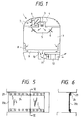
- Fig. 1 schematically shows one embodiment of a ventilating equipment for rolling stock.
- Figs. 2, 3 and 4 are respectively perspective views showing the operating state of an air flowpassage adjustable means of Fig. 1.
- Fig. 5 is a front view showing another embodiment of a flexible plate.
- Fig. 6 is a sectional view of a part taken on line VI-VI of Fig. 5.
- Fig. 7 schematically shows another embodiment of a ventilating equipment for rolling stock according to the present invention.
- Fig. 8 is a graph showing the relationship between air quantity Q and static pressure P in the blower shown in Fig. 7.
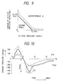
- Fig. 9 is a graph showing an uncomfortable region A with respect to the gradient dP/dt in change of pressure outside vehicle and the amount of change in pressure Px.
- Fig. 10 is a graph showing the change of the pressure outside vehicle Pout and the pressure inside vehicle Pin.
- reference numeral 1 designates an air supply equipment provided on the roof of the vehicle to drawn air outside the vehicle into the interior of the vehicle.
- Reference numeral 2 designates an outside-air in take grille formed on the roof of the vehicle, the air outside the vehicle is taken by the air supply equipment from the outside-air in take grille 2.
- Reference numeral 3 designates a blower which is an essential part constituting the air supply equipment 1.
- Reference numeral 4 designates an air flowpassage adjustable means on the air-supply side inscalled upstream from the blower 3 in the air flowpassage into which air outside the vehicle is taken.
- Reference numeral 5 designates a duct for introducing the air outside the vehicle taken into the interior of the vehicle by the air supply equipment 1 into the vehicle.
- the duct 5 is provided with a number of diffusers 6 for distributing air.
- the duct is mainly installed lengthwise of a ceiling portion of a passanger compartment 7.
- Reference numeral 10 designates an exhaust air equipment for discharging contaminated air within the passanger compartment 7 outside the vehicle.
- Reference numeral 9 designates an exhaust air duct for dischanging the contaminated air within the passenger compartment 7 to the exhaust air equipment 10.
- Reference numeral 8 designates an exhaust air grille mounted on an open portion within the passenger compartment 7 of the exhaust duct 9.
- Reference numeral 11 designates a blower which is an essential part which constitutes the exhaust air equipment 10.
- Reference numeral 12 designates an air flowpassage adjustable means on the exhaust side installed downstream from the blower 11 on the air flowpassage for discharging the contaminated air within the vehicle outside the vehicle. This air flowpassage adjustable means will be described in detail later.
- Reference numerals 20a and 20b designate flexible plates each having one end secured to the wall surface of an air flowpassage and the other being a free end which can freely swing.
- the flexible plates 20a and 20b are arranged at the right angle with respect to the air flowing direction.
- the shape of the flexible plates 20a and 20b coincides with the sectional shape of the air flowpassage and a swingable clearance is provided in the outer periphery to form a shape which blocks the air flowpassage.
- the flexible plates 20a and 20b are arranged alternately so that respective fixed ends are positioned on the opposite ends.
- a stopper 21a is provided upstream of the air flowpassage of the flexible plate 20a, and a stopper 21b is provided downstream of the air flowpassage of the flexible plate 20b.
- the stopper 21a supports the flexible plate 20a so that the flexible plate 20a will not deflect toward the upstream of the air flowpassage from the position at the right angle to the air flowing direction.
- the stopper 21b supports the flexible plate 20b so that the flexible plate 20b will not deflect toward the downstream of the air flowing passage from the position at the right angle to the air flowing direction.
- the flexible plate 20a has a rigidity by which the plate is not deflected when the normal air flow, as indicated by the dotted lines arrow in Figs. 2, 3 and 4, and has a rigidity by which when the air flow increases more than that of the normal state and the air flow indicated by the solid line arrow in Fig. 3 impinges upon the plate, the plate is deflected.
- the flexible plate 20b is lower in the rigidity than the flexible plate 20a, and has the rigidity to the extend that the flexible plate 20b is deflected a reverse flow of air as indicated by the solid line arrow in Fig. 4 occurs.
- Reference numeral 22a designates a guide plate provided upstream of the air flowpassage of the flexible plate 20a.
- the guide plate 22a has the size corresponding to the whole surface of the flexible plate 20a to prevent the air flow from directly applying the flexible plate 20a.
- the guide plate 22a has a curved shape for smoothly guiding the air flow.
- Reference numeral 22b designates a guide plate provided downstream of the air flowpassage of the flexible plate 20b.
- the guide plate 22b has the size corresponding to the whole surface of the flexible plate 20b to prevent the air flow from directly applying the flexible plate 20b in case of reverse air flow.
- Fig. 2 shows the normal ventilating state of the air flowpassage adjustable means. Both the flexible plates 20a and 20b stay still at the right angle to the air flow direction under the normal ventilating state.
- C and D When two vehicles pass each other during the running of the vehicles in the tunnel, pressure outside the vehicles suddenly changes as indicated by C and D in Fig. 10.
- the state shown at C in Fig. 10 shows the state that the pressure outside the vehicles suddenly increases.
- the function of the air flowpassage adjustable means 4 under this state will be described with reference to Fig. 3.
- the air flowpassage is shut off by the flexible plate 20a, thus the ventilation of the vehicle is not dore.
- the time when the vehicles pass each other within the tunnel and the duration of the change of pressure outside vehicles is only a few seconds. Accordingly, even if the air outside vehicles is not supplied into the vehicle, there occurs no problem.
- the function of the air flowpassage adjustable 4 when the pressure outside vehicles suddenly drops as indicated as D in Fig. 10 will be described with reference to Fig. 4.
- the air in the air flowpassage is reversed by the large change in pressure.
- the flexible plate 20b is deflected toward the flexible plate 20a as the result that the pressure on the side of the flexible plate 20a is lower.
- the area of the air flowpassage can be narrowed as the result that the flexible plate 20b deflects. Accordingly, the transmission of the pressure outside vehicle into the vehicle can be regulated. If the change in pressure outside vehicle is large, the flexible plate 20b shuts off the air flowpassage. At this time, a supply of air outside vehicle stops, which brings no problem because such duration of such a phenomenon is in a short period of time.
- the operating condition when the pressure outside vehicle of the air flowpassage adjustable means increases corresponds to that shown in Fig. 3.
- the operating condition, when the pressure outside vehicle of the air flowpassage adjustable means 12 decreases, corresponds to that shown in Fig. 4.
- the flexible plates 20a and 20b of the air flowpassage adjustable means 4 or 12 are deflected to narrow the area of the air flowpassage. If the pressure change is large, the air flowpassage is shut off. The air flowpassage is narrowed or shut off in this manner whereby the transmission of the change in pressure outside vehicle into the vehicle or the passanger compartment 7 can be prevented. Thus, the uncomfortableness to the passengers resulting from the change in pressure outside vehicle can be prevented.
- the flexible plate 20b has lower rigidity than the flexible plate 20a. That is, the flexible plate 20b is not deflected in the normal operating state since it is supported by the stopper 21b.
- the flexible plate 20b is formed to have a low rigidity so that incase a reverse flow occurs in the air flowpassage, the area of the air flowpassage can be rapidly narrowed.
- the reverse flow of air in the air flowpassage of the air supply equipment 3 and exhaust air equipment 10 causes the pressure in the vehicle to change rapidly. It is therefore particularly effective that when the reverse flow occurs, the area of the air flowpassage is rapidly narrowed.
- the guide plates 22a and 22b can prevent a deflection in excess of a specified value of the flexible plates 20a and 20b. Accordingly, by installation of the guide plates 22a and 22b corresponding to the flexible plates 20a and 20b as previously mentioned, the self-excitation oscillations of the flexible plates 20a and 20b can be prevented.
- Reference numeral 20c designates a flexible plate in which flaps 23 are mounted on both ends.
- the flaps 23 are mounted on the flexible plate 20c by supports 24 such as rivets, screws or the like.
- the flaps are in contact with the inner wall of the air flowpassage. Accordingly, by the deflection of the flexible plate 20c, the resistance due to the friction occurs between the flap 23 and the inner wall of the air flowpassage. The self-excitation oscillations of the flexible plate 20c can be prevented by the resistance. If the flaps 23 are provided on the flexible plate, said guide plates 22a and 22b need not be provided.
- the contact force of the flaps 23 on the inner wall of the air flowpassage or the rigidity and width of the flaps themselves can be freely adjusted by the rigidity of the flexible plate 20c or the maximum value of the change in pressure outside vehicle.
- reference numeral 31 designates an air supply equipment for taking air outside vehicles into the vehicle.
- Reference numeral 32 designates an outside-air intake grille mounted on the opening of the roof.
- Reference numeral 33 designates a blower constituting said air supply equipment 31.
- the blower 33 has the performance in which the flow quantity is less changed with respect to the variation in pressure outside vehicles.
- the performance of the blower 33 can be controlled stepwise. The lowest performance among the performance of the blower 33 is the performance which can supply the flow quantity as required into the vehicle under the normal operating condition.
- Reference numeral 34 designates a damper provided upstream from the blower 33 of the air flowpassage taking air outside vehicles into the vehicle. This damper can change an area of the air flowpassage installed. In other words, the damper 34 can change the resistance R of the air flowpassage.
- Reference numeral 35 designates a duct, which has the function similar to that of the duct 5 in the previous embodiment.
- Reference numeral 36 designates a diffusers provided in the duct 35.
- Reference numeral 37 designates a passenger compartment.
- Reference numeral 40 designates an exhaust air equipment for exhausting contaminated air within the vehicle outside the vehicle.
- Reference numeral 39 designates an exhaust duct for feeding contaminated air within the passanger compartment 37 toward the exhaust device 40.
- the exhaust duct 39 has the function similar to the exhaust duct 9 in the previous embodiment.
- Reference numeral 38 designates a grille mounted on the open portion within the passenger compartment 37.
- Reference numeral 41 designates a blower constituting an exhaust device 40.
- the blower 41 has the function similar to that of the previous blower 33.
- Reference numeral 42 designates a damper installed upstream of the blower 41 of the air flowpassage for exhausting contaminated air within the vehicle outside the vehicle. This damper 42 can change an area of the air flowpassage. In other words, the damper 42 can change the resistance R of the air flowpassage.
- the blowers 33 and 41 have the performance the solid lines P1-Q1, P2-Q2 and P3-Q3. The performance of the blowers 33 and 41 may be adjusted by varying the number of revolutions thereof.
- the dampers 34 and 42 have the resistance characteristics of the dotted lines R1, R2 and R3 in Fig. 8. The dampers 34 and 42 are controlled to provide different of resistance characteristic.
- Reference numeral 43 designates a pressure detector for detecting pressure outside vehicles.
- Reference numeral 44 designates a controller for controlling the blowers 33 and 41, the dampers 34 and 42 using, as the control inputs, the detected results which are sent from the pressure detector 43.
- the controller 44 calculates and judges the results of pressure detection obtained from the pressure detector 43, switches the performance of the blowers 33 and 41 and switches the resistance characteristics of the dampers 34 and 42.
- axis of abscissa represents time passage t (min), and the axis of ordinate represents pressure P (mm Aq).
- Fig. 9 shows the uncomfortableness region A in which passengers within the vehicle feed the uncomfortableness with respect to the absolute value Px of the change in pressure outside the vehicles and the variation gradient dP/dt in change of the pressure outside the vehicles.
- the axis of abscissa represents the absolute value Px of the change in pressure outside the vehicles and the axis of ordinate represents the gradient dP/dt in change of the pressure outside the vehicles.
- the hatched portion in Fig. 9 is the uncomfortable region A.
- This uncomfortable region A is experimentally known.
- the cause wherein passengers in the vehicle running at high speeds feel uncomfortable is the absolute value Px of the change in pressure outside the vehicles and the gradient dP/dt in change of the pressure outside the vehicles.
- the pressure outside the vehicles change as shown by P out in Fig. 10.
- the pressure outside the vehicles at that time are continuously detected by the pressure detector 43 to output the detection results to the controller 44.
- the controller 44 calculates and obtains the gradient dP/dt in change of the pressure outside the vehicles and the absolute value Px of the change in pressure outside the vehicles on the basis of the detected results which are sent from the pressure detector 43.
- the performance of the blowers 33 and 41 and the resistance characteristics of the dampers 34 and 42 given in Table 1 below are selected from values of dP/dt and Px obtained by the controller 8.
- the controller 44 outputs, as the control outputs, the results calculated and judged as mentioned above to the blowers 33, 41 and dampers 34, 42.
- the blowers 33, 41 and dampers 34, 42 are operated by the control output from the controller 44.
- a change in the maximum pressure P max occurs in a short period of time.
- the absolute value Px of the change in pressure and the gradient dP/dt in change of the pressure increase in value. If the absolute value Px of the change in pressure is less than the maximum pressure, for example, 400 mm Aq, of the blowers 33 and 41, the operation is made with the performance of blowers 33 and 41 in the range of minimum P3-Q3 to maximum P1-Q1.
- the dampers 34 and 42 are controlled in the range from R1 at which the resistance is minimum to R3 at which the resistance is maximum.
- the blowers 33 and 41 are controlled by the controller 44 to enhance the pressure characteristic of the blowers 33 and 41 as the absolute value Px of the change in pressure outside the vehicles increases, whereby the change in flow quantity resulting from the change in pressure outside the vehicles can be reduced.
- the operation is made so that the resistance of the dampers 34 and 42 increases as the dampers 34 and 42 of the controller 44 are controlled and the gradient dP/dt in change of the pressure outside the vehicles increases.
- the dampers 34 and 42 are completely closed. Also, if the absolute value Px of the change in pressure outside the vehicles exceeds the maximum pressure of the blowers 33 and 41, for example, 400 mm Aq, the dampers 34 and 42 are completely closed. Where the change in pressure outside the vehicles is extremely large, the vehicle is completely closed. The state wherein the pressure outside the vehicles is changed largely as described above is for a short period of time, causing no problem in securing the exhaust an quantity.
- the vehicle is closed, and therefore, it is possible to minimize the influence of the change in pressure outside the vehicles to the passengers can be eliminated.
Landscapes
- Engineering & Computer Science (AREA)
- Mechanical Engineering (AREA)
- Air-Conditioning For Vehicles (AREA)
Abstract
The ventilating equipment for rolling stock comprises an air supply means (31) for drawing air from the outside of a vehicle into the inside of a vehicle and an exhaust means (40) for exhausting air from the inside of the vehicle to the outside of the vehicle. In order to regulate a change in pressure within the vehicle resulting from a change in pressure outside the vehicle so as not to make passengers feel uncomfortable, in both the air flow passage on the air intake side of the air supply means (31) and the air flow passage on the air exhaust side of the exhaust means (40), damper means (34, 42) are disposed for adjusting the air flow passage areas. A pressure detecting means (43) is provided for detecting the outside air pressure. Further, a controller (44) sending a control command to the damper means (43, 42) is provided so as to adjust the air flow passage area in accordance with a value detected by that pressure detecting means (43) as a control input.
Description
- The present invention relates to ventilating equipment for rolling stock, and more particularly to a ventilating equipment for rolling stock suitable for rolling stock vehicles which run a tunnel at high speed.
- When rolling stock pass through the tunnel at high speed, the pressure around the vehicles rapidly changes. Particularly, when the vehicles pass each other within the tunnel, the change in pressure around the vehicles becomes maximum. When the pressure around the vehicles changes in a manner as described, a change in pressure is transmitted to the interior of the vehicles. Such a change in pressure brings forth an uncomfortable feeling to passengers and the like. To clear such a problem, Japanese Utility Model Publication No. 28166/1978 and the like have been known. That is, a ventilating equipment disclosed in said patent comprises an air supply means for supplying outside air into the air-tight vehicle and an exhaust means for discharging the contaminated air from the interior of the vehicle to the exterior. A blower constituting the aforesaid air supply means and exhaust means has the performance in which the flow quantity is less changed with respect to the change in pressure outside vehicles. Further, Japanese Patent Publication No. 9022/1983 has been known to disclose an arrangement how a change in interior pressure of the rolling stock vehicles is regulated. A ventilating equipment disclosed in said patent comprises an air supply means for supplying the outside air into the air-tight vehicle and an exhaust means for discharging contaminated air from the interior of the air-tight vehicle, wherein the amount of air from the air supply means and exhaust means, respectively, is controlled by a temperature difference between the interior and exterior of the vehicle.
- In Japanese Utility Model Publication No. 28166/1987 (corresponding to U.S. Patent No. 3,563,155), since each of blowers for the air supply means and exhaust means, respectively, is driven under the high output condition, noises or power consumption increases. In addition, the blower itself becomes large in size, causing a problem in that a large installation space is required.
- On the other hand, in Japanese Patent Publication No. 9022/1983, no consideration is taken into a variation in pressure around the vehicles when the rolling stock run the tunnel.
- It is an object of the present invention to provide a ventilating equipment for rolling stock which can regulate a change in pressure within the vehicle resulting from a sudden change in pressure outside the vehicle and simplify the construction of the ventilating equipment itself.
- According to the present invention, there is provided a ventilating equipment for rolling stock comprising an air supply means for drawing the outside air into an air-tight vehicle and an exhaust means for discharging air within the air-tight vehicle outside the vehicle, characterized in that on each of air flowpassages on the air draw-in side of the air supply means and the air-discharge side of the exhaust means is provided an air flowpassage adjustable means to change an area of each of said air flowpassages, said air flowpassage adjustable means being designed so as to change an area of each of said air flowpassages.
- Other objects of the present invention and the mode of embodiments thereof will be apparent from the ensuring description of the embodiments.
- Fig. 1 schematically shows one embodiment of a ventilating equipment for rolling stock.
- Figs. 2, 3 and 4 are respectively perspective views showing the operating state of an air flowpassage adjustable means of Fig. 1.
- Fig. 5 is a front view showing another embodiment of a flexible plate.
- Fig. 6 is a sectional view of a part taken on line VI-VI of Fig. 5.
- Fig. 7 schematically shows another embodiment of a ventilating equipment for rolling stock according to the present invention.
- Fig. 8 is a graph showing the relationship between air quantity Q and static pressure P in the blower shown in Fig. 7.
- Fig. 9 is a graph showing an uncomfortable region A with respect to the gradient dP/dt in change of pressure outside vehicle and the amount of change in pressure Px.
- Fig. 10 is a graph showing the change of the pressure outside vehicle Pout and the pressure inside vehicle Pin.
- One embodiment of the ventilating equipment for rolling stock according to the present invention will now be described with reference to Figs. 1, 2, 3 and 4. In these Figures,
reference numeral 1 designates an air supply equipment provided on the roof of the vehicle to drawn air outside the vehicle into the interior of the vehicle. Reference numeral 2 designates an outside-air in take grille formed on the roof of the vehicle, the air outside the vehicle is taken by the air supply equipment from the outside-air in take grille 2.Reference numeral 3 designates a blower which is an essential part constituting theair supply equipment 1.Reference numeral 4 designates an air flowpassage adjustable means on the air-supply side inscalled upstream from theblower 3 in the air flowpassage into which air outside the vehicle is taken. The detail construction of the air flowpassage adjustable means 4 will be described later.Reference numeral 5 designates a duct for introducing the air outside the vehicle taken into the interior of the vehicle by theair supply equipment 1 into the vehicle. Theduct 5 is provided with a number of diffusers 6 for distributing air. The duct is mainly installed lengthwise of a ceiling portion of apassanger compartment 7.Reference numeral 10 designates an exhaust air equipment for discharging contaminated air within thepassanger compartment 7 outside the vehicle.Reference numeral 9 designates an exhaust air duct for dischanging the contaminated air within thepassenger compartment 7 to theexhaust air equipment 10.Reference numeral 8 designates an exhaust air grille mounted on an open portion within thepassenger compartment 7 of theexhaust duct 9.Reference numeral 11 designates a blower which is an essential part which constitutes theexhaust air equipment 10.Reference numeral 12 designates an air flowpassage adjustable means on the exhaust side installed downstream from theblower 11 on the air flowpassage for discharging the contaminated air within the vehicle outside the vehicle. This air flowpassage adjustable means will be described in detail later. - The aforementioned air flow passage adjustable means 4 and 12 will be described in their construction.
-
Reference numerals flexible plates flexible plates flexible plates flexible plates flexible plate flexible plate stopper 21a is provided upstream of the air flowpassage of theflexible plate 20a, and astopper 21b is provided downstream of the air flowpassage of theflexible plate 20b. Thestopper 21a supports theflexible plate 20a so that theflexible plate 20a will not deflect toward the upstream of the air flowpassage from the position at the right angle to the air flowing direction. Thestopper 21b supports theflexible plate 20b so that theflexible plate 20b will not deflect toward the downstream of the air flowing passage from the position at the right angle to the air flowing direction. Incidentally, theflexible plate 20a has a rigidity by which the plate is not deflected when the normal air flow, as indicated by the dotted lines arrow in Figs. 2, 3 and 4, and has a rigidity by which when the air flow increases more than that of the normal state and the air flow indicated by the solid line arrow in Fig. 3 impinges upon the plate, the plate is deflected. On the other hand, theflexible plate 20b is lower in the rigidity than theflexible plate 20a, and has the rigidity to the extend that theflexible plate 20b is deflected a reverse flow of air as indicated by the solid line arrow in Fig. 4 occurs.Reference numeral 22a designates a guide plate provided upstream of the air flowpassage of theflexible plate 20a. Theguide plate 22a has the size corresponding to the whole surface of theflexible plate 20a to prevent the air flow from directly applying theflexible plate 20a. Theguide plate 22a has a curved shape for smoothly guiding the air flow.Reference numeral 22b designates a guide plate provided downstream of the air flowpassage of theflexible plate 20b. Theguide plate 22b has the size corresponding to the whole surface of theflexible plate 20b to prevent the air flow from directly applying theflexible plate 20b in case of reverse air flow. - The function of the air flowpassage adjustable means 4 and 12 will be described hereinafter with reference to Figs. 2, 3 and 4.
- Fig. 2 shows the normal ventilating state of the air flowpassage adjustable means. Both the
flexible plates adjustable means 4 under this state will be described with reference to Fig. 3. When the pressure outside the vehicles suddenly increases an described above as indicated by the solid line arrow, a pressure difference between upstream and downstream of the air flowpassage of theflexible plate 20a exceeds the rigidity of theflexible plate 20a due to the change in pressure, and therefore theflexible plate 20a deflects toward theflexible plate 20b. The area of the air flowpassage is narrowed by of theflexible plate 20a to regulate the function of the pressure outside vehicle into the vehicle. If the change in pressure outside vehicle is large, theflexible plate 20a is greatly deflected toward theflexible plate 20b to shut off air flowpassage. At that time, the change of the pressure outside vehicle will not be transmitted into the vehicle, and air outside vehicle will not be supplied into the vehicle. The air flowpassage is shut off by theflexible plate 20a, thus the ventilation of the vehicle is not dore. However, the time when the vehicles pass each other within the tunnel and the duration of the change of pressure outside vehicles is only a few seconds. Accordingly, even if the air outside vehicles is not supplied into the vehicle, there occurs no problem. - The function of the air flowpassage adjustable 4 when the pressure outside vehicles suddenly drops as indicated as D in Fig. 10 will be described with reference to Fig. 4. When the change in pressure on the negative pressure side is transmitted between the
flexible plate 20a and theflexible plate 20b as indicated by the solid line arrow in Fig. 4, the air in the air flowpassage is reversed by the large change in pressure. Theflexible plate 20b is deflected toward theflexible plate 20a as the result that the pressure on the side of theflexible plate 20a is lower. The area of the air flowpassage can be narrowed as the result that theflexible plate 20b deflects. Accordingly, the transmission of the pressure outside vehicle into the vehicle can be regulated. If the change in pressure outside vehicle is large, theflexible plate 20b shuts off the air flowpassage. At this time, a supply of air outside vehicle stops, which brings no problem because such duration of such a phenomenon is in a short period of time. - The operating condition when the pressure outside vehicle of the air flowpassage adjustable means increases, corresponds to that shown in Fig. 3. The operating condition, when the pressure outside vehicle of the air flowpassage adjustable means 12 decreases, corresponds to that shown in Fig. 4.
- When the change in pressure outside vehicle suddenly occurs whereby said pressure change is directly transmitted to the
flexible plate flexible plate flexible plate flexible plate Guide plates flexible plates guide plates flexible plates flexible plates - According to the arrangement as described above, when the sudden change in pressure outside vehicle occurs, the
flexible plates adjustable means passanger compartment 7 can be prevented. Thus, the uncomfortableness to the passengers resulting from the change in pressure outside vehicle can be prevented. - Next, the
flexible plate 20b has lower rigidity than theflexible plate 20a. That is, theflexible plate 20b is not deflected in the normal operating state since it is supported by thestopper 21b. However, when a reverse flow occurs in the air flowpassage as shown by the solid line arrow in Fig. 4, it is necessary to quickly narrow the area of the air flowpassage. Thus, theflexible plate 20b is formed to have a low rigidity so that incase a reverse flow occurs in the air flowpassage, the area of the air flowpassage can be rapidly narrowed. The reverse flow of air in the air flowpassage of theair supply equipment 3 andexhaust air equipment 10 causes the pressure in the vehicle to change rapidly. It is therefore particularly effective that when the reverse flow occurs, the area of the air flowpassage is rapidly narrowed. - Next, the
guide plates flexible plates guide plates flexible plates flexible plates - Another embodiment of the
flexible plates Reference numeral 20c designates a flexible plate in which flaps 23 are mounted on both ends. Theflaps 23 are mounted on theflexible plate 20c bysupports 24 such as rivets, screws or the like. The flaps are in contact with the inner wall of the air flowpassage. Accordingly, by the deflection of theflexible plate 20c, the resistance due to the friction occurs between theflap 23 and the inner wall of the air flowpassage. The self-excitation oscillations of theflexible plate 20c can be prevented by the resistance. If theflaps 23 are provided on the flexible plate, saidguide plates - The contact force of the
flaps 23 on the inner wall of the air flowpassage or the rigidity and width of the flaps themselves can be freely adjusted by the rigidity of theflexible plate 20c or the maximum value of the change in pressure outside vehicle. - Next, another embodiment of the ventilating equipment for rolling stock according to the present invention will be described with reference to Figs. 7, 8, 9 and 10. In these Figures,
reference numeral 31 designates an air supply equipment for taking air outside vehicles into the vehicle.Reference numeral 32 designates an outside-air intake grille mounted on the opening of the roof.Reference numeral 33 designates a blower constituting saidair supply equipment 31. Theblower 33 has the performance in which the flow quantity is less changed with respect to the variation in pressure outside vehicles. The performance of theblower 33 can be controlled stepwise. The lowest performance among the performance of theblower 33 is the performance which can supply the flow quantity as required into the vehicle under the normal operating condition.Reference numeral 34 designates a damper provided upstream from theblower 33 of the air flowpassage taking air outside vehicles into the vehicle. This damper can change an area of the air flowpassage installed. In other words, thedamper 34 can change the resistance R of the air flowpassage.Reference numeral 35 designates a duct, which has the function similar to that of theduct 5 in the previous embodiment.Reference numeral 36 designates a diffusers provided in theduct 35.Reference numeral 37 designates a passenger compartment.Reference numeral 40 designates an exhaust air equipment for exhausting contaminated air within the vehicle outside the vehicle.Reference numeral 39 designates an exhaust duct for feeding contaminated air within thepassanger compartment 37 toward theexhaust device 40. Theexhaust duct 39 has the function similar to theexhaust duct 9 in the previous embodiment.Reference numeral 38 designates a grille mounted on the open portion within thepassenger compartment 37.Reference numeral 41 designates a blower constituting anexhaust device 40. Theblower 41 has the function similar to that of theprevious blower 33.Reference numeral 42 designates a damper installed upstream of theblower 41 of the air flowpassage for exhausting contaminated air within the vehicle outside the vehicle. Thisdamper 42 can change an area of the air flowpassage. In other words, thedamper 42 can change the resistance R of the air flowpassage. - The
blowers blowers dampers dampers -
Reference numeral 43 designates a pressure detector for detecting pressure outside vehicles.Reference numeral 44 designates a controller for controlling theblowers dampers pressure detector 43. Thecontroller 44 calculates and judges the results of pressure detection obtained from thepressure detector 43, switches the performance of theblowers dampers - When the vehicles run at a speed of 200 km/hr, for example, and pass each other in the tunnel, the pressure outside the vehicle changes as shown by the curve Pout in Fig. 10. That is, in the stage before the vehicles pass each other, the pressure outside the vehicles increases up to 198 mm Aq at the maximum. On the other hand, after the vehicles pass each other, the pressure outside the vehicles suddenly lowers down to -491 mm Aq.
- In Fig. 10, the axis of abscissa represents time passage t (min), and the axis of ordinate represents pressure P (mm Aq).
- Fig. 9 shows the uncomfortableness region A in which passengers within the vehicle feed the uncomfortableness with respect to the absolute value Px of the change in pressure outside the vehicles and the variation gradient dP/dt in change of the pressure outside the vehicles. In Fig. 9, the axis of abscissa represents the absolute value Px of the change in pressure outside the vehicles and the axis of ordinate represents the gradient dP/dt in change of the pressure outside the vehicles. The hatched portion in Fig. 9 is the uncomfortable region A. This uncomfortable region A is experimentally known. The cause wherein passengers in the vehicle running at high speeds feel uncomfortable is the absolute value Px of the change in pressure outside the vehicles and the gradient dP/dt in change of the pressure outside the vehicles.
- In such an arrangement as described above, controls of the
blowers dampers controller 44 will be described hereinafter. - When the vehicles run into the tunnel at high speed and pass each other, the pressure outside the vehicles change as shown by Pout in Fig. 10. The pressure outside the vehicles at that time are continuously detected by the
pressure detector 43 to output the detection results to thecontroller 44. Thecontroller 44 calculates and obtains the gradient dP/dt in change of the pressure outside the vehicles and the absolute value Px of the change in pressure outside the vehicles on the basis of the detected results which are sent from thepressure detector 43. The performance of theblowers dampers controller 8.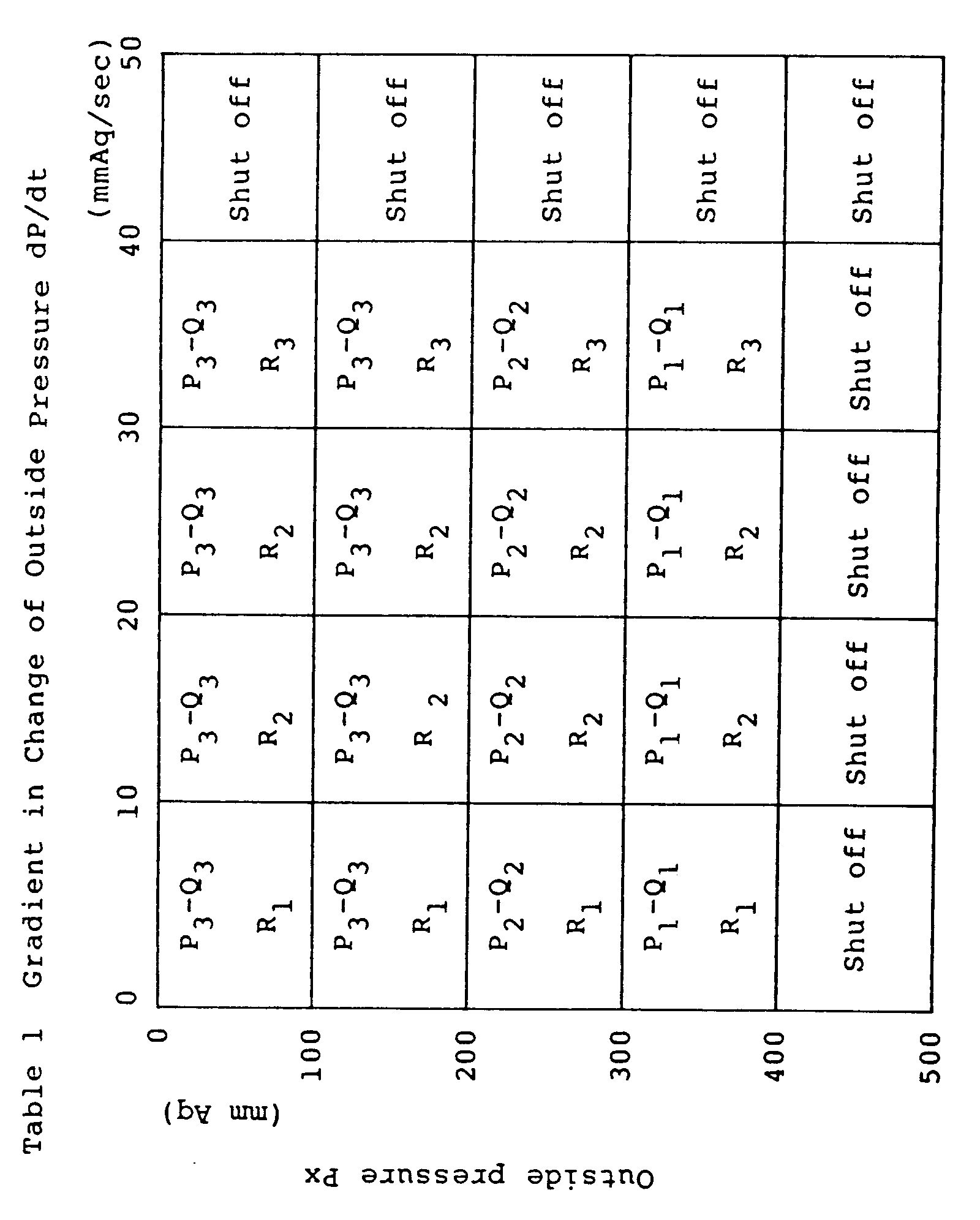
- The
controller 44 outputs, as the control outputs, the results calculated and judged as mentioned above to theblowers dampers blowers dampers controller 44. For example, where the pressure outside the vehicles is changed as shown in Fig. a change in the maximum pressure Pmax occurs in a short period of time. Accordingly, the absolute value Px of the change in pressure and the gradient dP/dt in change of the pressure increase in value. If the absolute value Px of the change in pressure is less than the maximum pressure, for example, 400 mm Aq, of theblowers blowers dampers blowers controller 44 to enhance the pressure characteristic of theblowers dampers dampers controller 44 are controlled and the gradient dP/dt in change of the pressure outside the vehicles increases. Thedampers blowers 33 and resulting from the change in pressure outside the vehicles can be regulated and the transmission of the pressure outside the vehicles into the vehicle can be regulated, and therefore, the variation is pressure within the vehicle can be regulated at minimum. - If the gradient dP/dt in change of the pressure outside the vehicles exceeds the value at which passengers feel uncomfortable, for example, 40 mm Aq/sec., the
dampers blowers dampers - In the present embodiment, if the absolute value Px of the change in pressure outside the vehicles and the variation gradient dP/dt in change of the pressure outside the vehicles are within the uncomfortable region A, ventilation is continuously carried out. At this time, the performance of the
blowers dampers - As described above, in the present invention, it is possible to regulate the change in pressure within the vehicle resulting from the variation in pressure outside the vehicles. Accordingly, the uncomfortable condition will not occur to the passengers.
Claims (2)
- A ventilating equipment for rolling stock comprising an air supply means (31) for drawing air from the outside of a vehicle into the inside of a vehicle and an exhaust means (40) for exhausting air from the inside of the vehicle to the outside of the vehicle,
characterized in that in both the air flowpassage on the air intake side of said air supply means (31) and the air flowpassage on the air exhaust side of said exhaust means (40), damper means (34, 42) are disposed for adjusting the air flowpassage areas, a pressure detecting means (43) is provided for detecting the outside air pressure, and a controller (44) is provided sending a control command to said damper means (34, 42) so as to adjust the air flowpassage area in accordance with a value detected by said pressure detecting means (43), as a control input. - A method of controlling a ventilating equipment for rolling stock, comprising an air supply means (31) for drawing air from the outside of a vehicle into the inside of the vehicle and an exhaust means (40) for exhausting air from the inside of the vehicle to the outside of the vehicle,
characterized in that there are provided damper means (34, 42) in said air flowpassages of the air supply means (31) and the exhaust means (40), for adjusting the areas of the air flowpassages, said method comprising the steps of continuously detecing the outside air pressure; obtaining a gradient of change in the outside air pressure and a change in the outside air pressure in accordance with the detected results; and causing said damper means (34, 42) to adjust the areas of said air flowpassages when said gradient of change in pressure or said change in pressure exceeds a set value.
Priority Applications (2)
| Application Number | Priority Date | Filing Date | Title |
|---|---|---|---|
| EP92116206A EP0523752A1 (en) | 1987-11-02 | 1988-10-31 | Ventilating equipment for rolling stock |
| EP95108526A EP0678434A1 (en) | 1987-11-02 | 1988-10-31 | Ventilating method and equipment for rolling stock |
Applications Claiming Priority (7)
| Application Number | Priority Date | Filing Date | Title |
|---|---|---|---|
| JP62275761A JPH0723091B2 (en) | 1987-11-02 | 1987-11-02 | Vehicle pressure relief device |
| JP275761/87 | 1987-11-02 | ||
| JP175091/87U | 1987-11-18 | ||
| JP17509187U JPH0635853Y2 (en) | 1987-11-18 | 1987-11-18 | Vehicle pressure relief device |
| JP32703487A JPH01168560A (en) | 1987-12-25 | 1987-12-25 | Vehicle ventilation system |
| JP327034/87 | 1987-12-25 | ||
| EP92116206A EP0523752A1 (en) | 1987-11-02 | 1988-10-31 | Ventilating equipment for rolling stock |
Related Parent Applications (1)
| Application Number | Title | Priority Date | Filing Date |
|---|---|---|---|
| EP88118132.5 Division | 1988-10-31 |
Related Child Applications (2)
| Application Number | Title | Priority Date | Filing Date |
|---|---|---|---|
| EP95108526.5 Division-Into | 1988-10-31 | ||
| EP95108526A Division EP0678434A1 (en) | 1987-11-02 | 1988-10-31 | Ventilating method and equipment for rolling stock |
Publications (1)
| Publication Number | Publication Date |
|---|---|
| EP0523752A1 true EP0523752A1 (en) | 1993-01-20 |
Family
ID=27442341
Family Applications (2)
| Application Number | Title | Priority Date | Filing Date |
|---|---|---|---|
| EP92116206A Withdrawn EP0523752A1 (en) | 1987-11-02 | 1988-10-31 | Ventilating equipment for rolling stock |
| EP95108526A Withdrawn EP0678434A1 (en) | 1987-11-02 | 1988-10-31 | Ventilating method and equipment for rolling stock |
Family Applications After (1)
| Application Number | Title | Priority Date | Filing Date |
|---|---|---|---|
| EP95108526A Withdrawn EP0678434A1 (en) | 1987-11-02 | 1988-10-31 | Ventilating method and equipment for rolling stock |
Country Status (1)
| Country | Link |
|---|---|
| EP (2) | EP0523752A1 (en) |
Cited By (4)
| Publication number | Priority date | Publication date | Assignee | Title |
|---|---|---|---|---|
| EP0620392A1 (en) * | 1993-04-16 | 1994-10-19 | Gec Alsthom Transport Sa | Device to prevent or limit sudden pressure changes in vehicles, especially in land crafts |
| DE19637309A1 (en) * | 1996-09-13 | 1998-03-19 | Abb Patent Gmbh | Device for ventilation of a rail vehicle |
| WO2015176879A1 (en) * | 2014-05-20 | 2015-11-26 | Siemens Aktiengesellschaft | Vehicle with a ventilation system |
| EP3674169A4 (en) * | 2017-08-22 | 2021-06-02 | CRRC Qingdao Sifang Co., Ltd. | AUTOMATIC EXHAUST VENTILATION DOOR AND VEHICLE BODY CONTROL DEVICE CONTAINING IT |
Families Citing this family (4)
| Publication number | Priority date | Publication date | Assignee | Title |
|---|---|---|---|---|
| DE102007019014A1 (en) * | 2007-04-18 | 2008-10-23 | Thyssenkrupp Transrapid Gmbh | Method and apparatus for avoiding rapid changes in internal pressure in a closed space |
| JP2012071680A (en) * | 2010-09-28 | 2012-04-12 | Hitachi Ltd | Railway vehicle including air intake device, exhaust device and exhaust blower, and method for controlling air intake device, exhaust device and exhaust blower provided in railway vehicle |
| CN103273935A (en) * | 2013-06-20 | 2013-09-04 | 南车南京浦镇车辆有限公司 | Method for assembling guiding air duct for metro trains |
| WO2022013937A1 (en) * | 2020-07-14 | 2022-01-20 | 株式会社日立製作所 | Railroad car |
Citations (7)
| Publication number | Priority date | Publication date | Assignee | Title |
|---|---|---|---|---|
| DE1530049A1 (en) * | 1965-09-09 | 1970-08-20 | Licentia Gmbh | Ventilation device for electrically operated rail vehicles |
| US3563155A (en) | 1967-12-27 | 1971-02-16 | Japan National Railway | Ventilating equipment for high speed train |
| US3593644A (en) * | 1969-04-21 | 1971-07-20 | Toraichi Shinya | Railroad car ventilator |
| JPS5328166U (en) | 1976-08-18 | 1978-03-10 | ||
| JPS589022A (en) | 1981-06-15 | 1983-01-19 | イング・チイ・オリベツチ・アンド・チイ・エス・ピ−・ア | optical transducer |
| EP0143931A2 (en) * | 1983-12-01 | 1985-06-12 | Messerschmitt-Bölkow-Blohm Gesellschaft mit beschränkter Haftung | Aeration and air conditioning device for railway coaches |
| JPS6228166U (en) | 1985-08-06 | 1987-02-20 |
Family Cites Families (4)
| Publication number | Priority date | Publication date | Assignee | Title |
|---|---|---|---|---|
| DE1917999A1 (en) * | 1969-04-09 | 1970-10-15 | Daimler Benz Ag | Device for supplying fresh air in vehicles, in particular in motor vehicles |
| DE3603802A1 (en) * | 1986-02-07 | 1987-08-13 | Bbc Brown Boveri & Cie | VENTILATION OPENINGS ON HIGH SPEED VEHICLES, ESPECIALLY HIGH SPEED RAIL VEHICLES |
| DE3618292C3 (en) * | 1986-05-30 | 1995-12-07 | Rainer Herma | Motor-operated pressure valve for cabins of railroad cars |
| FR2693698B1 (en) * | 1992-07-16 | 1994-08-19 | Alsthom Gec | Device for suppressing sudden variations in pressure in vehicles, in particular in land vehicles. |
-
1988
- 1988-10-31 EP EP92116206A patent/EP0523752A1/en not_active Withdrawn
- 1988-10-31 EP EP95108526A patent/EP0678434A1/en not_active Withdrawn
Patent Citations (7)
| Publication number | Priority date | Publication date | Assignee | Title |
|---|---|---|---|---|
| DE1530049A1 (en) * | 1965-09-09 | 1970-08-20 | Licentia Gmbh | Ventilation device for electrically operated rail vehicles |
| US3563155A (en) | 1967-12-27 | 1971-02-16 | Japan National Railway | Ventilating equipment for high speed train |
| US3593644A (en) * | 1969-04-21 | 1971-07-20 | Toraichi Shinya | Railroad car ventilator |
| JPS5328166U (en) | 1976-08-18 | 1978-03-10 | ||
| JPS589022A (en) | 1981-06-15 | 1983-01-19 | イング・チイ・オリベツチ・アンド・チイ・エス・ピ−・ア | optical transducer |
| EP0143931A2 (en) * | 1983-12-01 | 1985-06-12 | Messerschmitt-Bölkow-Blohm Gesellschaft mit beschränkter Haftung | Aeration and air conditioning device for railway coaches |
| JPS6228166U (en) | 1985-08-06 | 1987-02-20 |
Cited By (6)
| Publication number | Priority date | Publication date | Assignee | Title |
|---|---|---|---|---|
| EP0620392A1 (en) * | 1993-04-16 | 1994-10-19 | Gec Alsthom Transport Sa | Device to prevent or limit sudden pressure changes in vehicles, especially in land crafts |
| FR2704040A1 (en) * | 1993-04-16 | 1994-10-21 | Gec Alsthom Transport Sa | Device for suppressing or limiting sudden pressure changes in vehicles, particularly in land vehicles. |
| DE19637309A1 (en) * | 1996-09-13 | 1998-03-19 | Abb Patent Gmbh | Device for ventilation of a rail vehicle |
| WO2015176879A1 (en) * | 2014-05-20 | 2015-11-26 | Siemens Aktiengesellschaft | Vehicle with a ventilation system |
| RU177453U1 (en) * | 2014-05-20 | 2018-02-21 | Сименс Акциенгезелльшафт | VEHICLE WITH VENTILATION SYSTEM |
| EP3674169A4 (en) * | 2017-08-22 | 2021-06-02 | CRRC Qingdao Sifang Co., Ltd. | AUTOMATIC EXHAUST VENTILATION DOOR AND VEHICLE BODY CONTROL DEVICE CONTAINING IT |
Also Published As
| Publication number | Publication date |
|---|---|
| EP0678434A1 (en) | 1995-10-25 |
Similar Documents
| Publication | Publication Date | Title |
|---|---|---|
| EP0315108A2 (en) | Ventilating equipment for rolling stock | |
| US5413528A (en) | Air conditioning system for motor vehicles | |
| JP2894104B2 (en) | VEHICLE VENTILATION DEVICE AND CONTROL METHOD THEREOF | |
| KR960703476A (en) | Method and Control System For Controlling An Automotive HVAC System | |
| EP0523752A1 (en) | Ventilating equipment for rolling stock | |
| US20100052364A1 (en) | Vehicle cowl box structure | |
| JPH0316583B2 (en) | ||
| JPS56160213A (en) | Air conditioning controller for automobile | |
| US5813600A (en) | Method for operating a heating and/or air conditioning system | |
| US4343230A (en) | Auxiliary device for climate-control units in motor vehicles | |
| KR20000011426A (en) | Air supply apparatus and method for regulating the air supply in a vehicle | |
| JPH0986138A (en) | Vehicle air conditioning controller | |
| US4246918A (en) | Method and apparatus for forced air balancing of damper blades | |
| FI77216B (en) | REGLERINGSANORDNING FOER BLAOSTRYCKET I EN GLASHAERDNINGSANORDNINGS KYLMUNSTYCKEN. | |
| US3387549A (en) | Air-conditioning devices for vehicles | |
| US5868312A (en) | Climate control device for motor vehicles | |
| JPH0516652A (en) | Air conditioner for bus vehicle | |
| JP4457301B2 (en) | Air conditioning system for vehicles | |
| US5167273A (en) | Aspirator tube check valve assembly and method of continuously sensing vehicular interior compartment air temperature | |
| US3760706A (en) | Control installation for air or gas streams of ventilation systems | |
| US20250282199A1 (en) | Air Discharge System for a Vehicle | |
| JPH0577726A (en) | Vehicle ventilation device and control method thereof | |
| JPH09104344A (en) | Vehicle ventilation method and device | |
| JPH01168560A (en) | Vehicle ventilation system | |
| JP3597515B2 (en) | Vehicle ventilation system |
Legal Events
| Date | Code | Title | Description |
|---|---|---|---|
| PUAI | Public reference made under article 153(3) epc to a published international application that has entered the european phase |
Free format text: ORIGINAL CODE: 0009012 |
|
| 17P | Request for examination filed |
Effective date: 19920922 |
|
| AC | Divisional application: reference to earlier application |
Ref document number: 315108 Country of ref document: EP |
|
| AK | Designated contracting states |
Kind code of ref document: A1 Designated state(s): DE FR GB IT |
|
| 17Q | First examination report despatched |
Effective date: 19950111 |
|
| 18W | Application withdrawn |
Withdrawal date: 19950809 |