EP0522855A1 - Form-fill-seal type packaging machine - Google Patents
Form-fill-seal type packaging machine Download PDFInfo
- Publication number
- EP0522855A1 EP0522855A1 EP92306313A EP92306313A EP0522855A1 EP 0522855 A1 EP0522855 A1 EP 0522855A1 EP 92306313 A EP92306313 A EP 92306313A EP 92306313 A EP92306313 A EP 92306313A EP 0522855 A1 EP0522855 A1 EP 0522855A1
- Authority
- EP
- European Patent Office
- Prior art keywords
- film
- former
- packaging machine
- skirt
- path
- Prior art date
- Legal status (The legal status is an assumption and is not a legal conclusion. Google has not performed a legal analysis and makes no representation as to the accuracy of the status listed.)
- Granted
Links
- 238000004806 packaging method and process Methods 0.000 title claims abstract description 23
- 238000007789 sealing Methods 0.000 claims abstract description 6
- 230000011664 signaling Effects 0.000 claims 1
- 238000011144 upstream manufacturing Methods 0.000 description 10
- 230000000694 effects Effects 0.000 description 3
- 230000003213 activating effect Effects 0.000 description 1
- 230000002411 adverse Effects 0.000 description 1
- 238000001514 detection method Methods 0.000 description 1
- 230000004048 modification Effects 0.000 description 1
- 238000012986 modification Methods 0.000 description 1
Images


Classifications
-
- B—PERFORMING OPERATIONS; TRANSPORTING
- B65—CONVEYING; PACKING; STORING; HANDLING THIN OR FILAMENTARY MATERIAL
- B65B—MACHINES, APPARATUS OR DEVICES FOR, OR METHODS OF, PACKAGING ARTICLES OR MATERIALS; UNPACKING
- B65B9/00—Enclosing successive articles, or quantities of material, e.g. liquids or semiliquids, in flat, folded, or tubular webs of flexible sheet material; Subdividing filled flexible tubes to form packages
- B65B9/10—Enclosing successive articles, or quantities of material, in preformed tubular webs, or in webs formed into tubes around filling nozzles, e.g. extruded tubular webs
- B65B9/20—Enclosing successive articles, or quantities of material, in preformed tubular webs, or in webs formed into tubes around filling nozzles, e.g. extruded tubular webs the webs being formed into tubes in situ around the filling nozzles
- B65B9/22—Forming shoulders; Tube formers
-
- B—PERFORMING OPERATIONS; TRANSPORTING
- B65—CONVEYING; PACKING; STORING; HANDLING THIN OR FILAMENTARY MATERIAL
- B65B—MACHINES, APPARATUS OR DEVICES FOR, OR METHODS OF, PACKAGING ARTICLES OR MATERIALS; UNPACKING
- B65B41/00—Supplying or feeding container-forming sheets or wrapping material
- B65B41/12—Feeding webs from rolls
- B65B41/16—Feeding webs from rolls by rollers
-
- B—PERFORMING OPERATIONS; TRANSPORTING
- B65—CONVEYING; PACKING; STORING; HANDLING THIN OR FILAMENTARY MATERIAL
- B65B—MACHINES, APPARATUS OR DEVICES FOR, OR METHODS OF, PACKAGING ARTICLES OR MATERIALS; UNPACKING
- B65B57/00—Automatic control, checking, warning, or safety devices
-
- B—PERFORMING OPERATIONS; TRANSPORTING
- B65—CONVEYING; PACKING; STORING; HANDLING THIN OR FILAMENTARY MATERIAL
- B65B—MACHINES, APPARATUS OR DEVICES FOR, OR METHODS OF, PACKAGING ARTICLES OR MATERIALS; UNPACKING
- B65B59/00—Arrangements to enable machines to handle articles of different sizes, to produce packages of different sizes, to vary the contents of packages, to handle different types of packaging material, or to give access for cleaning or maintenance purposes
- B65B59/04—Machines constructed with readily-detachable units or assemblies, e.g. to facilitate maintenance
-
- B—PERFORMING OPERATIONS; TRANSPORTING
- B65—CONVEYING; PACKING; STORING; HANDLING THIN OR FILAMENTARY MATERIAL
- B65B—MACHINES, APPARATUS OR DEVICES FOR, OR METHODS OF, PACKAGING ARTICLES OR MATERIALS; UNPACKING
- B65B9/00—Enclosing successive articles, or quantities of material, e.g. liquids or semiliquids, in flat, folded, or tubular webs of flexible sheet material; Subdividing filled flexible tubes to form packages
- B65B9/10—Enclosing successive articles, or quantities of material, in preformed tubular webs, or in webs formed into tubes around filling nozzles, e.g. extruded tubular webs
- B65B9/20—Enclosing successive articles, or quantities of material, in preformed tubular webs, or in webs formed into tubes around filling nozzles, e.g. extruded tubular webs the webs being formed into tubes in situ around the filling nozzles
- B65B9/213—Enclosing successive articles, or quantities of material, in preformed tubular webs, or in webs formed into tubes around filling nozzles, e.g. extruded tubular webs the webs being formed into tubes in situ around the filling nozzles the web having intermittent motion
Definitions
- This invention relates to a so-called form-fill-seal type packaging machine having an improved device for transporting an elongated flexible film material from which bags are to be made by means of a former.
Landscapes
- Engineering & Computer Science (AREA)
- Mechanical Engineering (AREA)
- Containers And Plastic Fillers For Packaging (AREA)
- Registering, Tensioning, Guiding Webs, And Rollers Therefor (AREA)
Abstract
Description
- This invention relates to a so-called form-fill-seal type packaging machine having an improved device for transporting an elongated flexible film material from which bags are to be made by means of a former.
- As shown in Fig. 3, a prior art packaging machine of the form-fill-seal type may be characterized as having a
frame 2 which is vertically slidable with respect to a base 7 and a film roll 1 supported by acantilevered shaft 3 which extends perpendicularly to the front-back direction of the machine. An elongated flexible bag-forming material (hereinafter referred to as a film 4) is pulled out of the film roll 1 and is directed in the forward direction to a former 6 throughguide rollers dancer roller 10. The former 6 is of a conventional kind, having a skirt-like structure 12 (hereinafter simply referred to as "the skirt") and serving to transform thefilm 4 into a cylindrical shape. - The overlapping side edges of the film are sealed together by means of a
vertical sealer 61 to form a tube, and anend sealer 62 is operated to seal the tube at top and bottom positions to form a bag. - Prior art packaging machines thus structured encounter several problems. Firstly, although one of the guide rollers (32) at the downstream end (along the path of travel by the
film 4 from the film roll 1 to the former 6) is normally placed adjacent to theskirt 12 so as to be able to guide thefilm 4 smoothly over to the former 6, it must be removed away from its normal position when thefilm 4 is initially set or when the former 6 is to be replaced by another of a different kind. Since such removal operations are usually carried out manually, workability of the machine is adversely affected. Secondly, thefilm 4 must be prevented from moving in a zigzag because its side edge portions should desirably always overlap by the same amount. Although a means is generally provided for straightening thefilm 4 as it begins to slide transversely to its direction of intended motion, such film-straightening means should be placed as close to the former 6 as possible in order to be effective. If it is too close to the former 6, however, it will stand in the way of the operator when thefilm 4 is set or the former 6 is exchanged, as mentioned above. Moreover, the film-straightening means will include means for detecting the deviation of thefilm 4 from its normal course, and this will have the undesirable effect of increasing the number of components of the machine and complicating its structure. - In accordance with the present invention, a form-fill-seal type packaging machine comprises:
a former having a skirt-like structure for forming an elongated film pulled out of a film roll into a tubular shape;
a longitudinal sealer for longitudinally sealing side edges of said pulled out film;
an end sealer for transversely sealing said tubularly formed film at top and bottom ends to thereby form a bag;
an elongated guiding member for guiding said film to said skirt-like structure;
a slidable member supporting said guiding member and adapted to move selectively towards or away from said skirt-like structure; and
a positioning mechanism for automatically stopping said slidable member so as to position said guiding member adjacent to said skirt-like structure. - The present invention eliminates the disadvantages of prior art packaging machines described above by providing a packaging machine with an improved film-transporting device such that its guide roller and, in some cases film-straightening means, can be retracted automatically without requiring the operator's manual operations when the film is initially set or the former is exchanged such that the workability of the machine can be improved. This can be accomplished without unduly increasing the number of components or the overall size of the machine.
- In one example, an elongate film pulled out of a film roll is made into a cylindrical shape by leading it to the skirt of the former with the help of a roll-like elongated guiding member, a longitudinal sealer seals its side edges together to form a tube, and an end sealer seals it transversely at top and bottom ends to thereby form a bag. A sliding member is provided such that the guiding member for leading the film to the skirt of the former can be retracted from its normal position adjacent to the skirt. This sliding member is provided with a positioning mechanism for stopping the guiding member adjacent to the skirt when it is brought closer to the former from its retracted position by the sliding member. The sliding member is further provided with a mechanism for correcting the effects of transverse deviations of the film from its intended travel path. This mechanism is comprised of a pair of elongated members which are maintained parallel to each other and a means for rotating them within the plane of the motion of the film. One of these elongated members is provided with a load cell and is adapted to detect the tension within the film. The output from this load cell is inputted as a feedback to the control device for controlling the pulling of the film from the film roll, thereby adjusting the film tension to a preset level.
- With a packaging machine thus structured, both the guiding member and the mechanism for correcting the transverse deviations of the film path can be retracted away from the former so as not to be in the way of the operator when, for example, a new film is set in the path or the former is removed to be replaced by a new one. After the operator's job is done, the sliding member is automatically stopped such that the guiding member is positioned adjacent to the skirt of the former.
- The accompanying drawings, which are incorporated in and form a part of this specification, illustrate an embodiment of the invention and, together with the description, serve to explain the principles of the invention and the prior art. In the drawings:
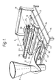
- Fig. 1 is a perspective view of some of essential parts of a film-transporting device for a packaging machine embodying the present invention;
- Fig. 2 is a partially sectional side view of the film-transporting device of Fig. 1; and
- Fig. 3 is a diagonal view of an example of prior art packaging machine of the form-fill-seal type.
- A packaging machine embodying an example of the invention will be described with reference to Figs. 1 and 2. In these figures, components and parts which are identical or substantially similar to those described above with reference to the prior art machine of Fig. 3 will be indicated by the same numerals and will not be explained separately.
- In Fig. 1,
numeral 15 indicates the ceiling of the housing for the packaging machine. A guide roller (referred to as the upstream guide roller 16) is axially supported on theceiling 15 away from the former 6 and extending perpendicularly to the direction of the path of thefilm 4 such that thefilm 4, which is pulled upwards from the film roll (not shown in Fig. 1), is directed forward towards the former 6. A supportingplate 17 with a parallel pair ofguide rails 18 directed towards the former 6 is provided on top of theceiling 15, and abase plate 19 is placed parallel to and above the supportingplate 17.Sliders 21, which engage and slide along theguide rails 18, are attached to the bottom surface of thebase plate 19 such that thebase plate 19 itself can slidably move towards or away from the former 6. On the top surface of thebase plate 19 proximally to the former 6, another guide roller (referred to as the downstream guide roller 32) is axially supported parallel to theupstream guide roller 16. As shown in Fig. 2, a pair oflegs 22 is also attached to the bottom surface of thebase plate 19, extending downward through an opening (not shown) in theceiling 15 of the machine housing and the supportingplate 17. Aconnector shaft 23 between theselegs 22 is provided with anut 24 engaging ascrew shaft 27 which extends parallel to theguide rails 18 and is adapted to be rotated by amotor 26 contained inside the housing for the packaging machine. - In Fig. 2,
numeral 31 generally indicates a film-straightening device according to the present invention, provided near the former 6 on its upstream side (with reference to the direction of motion of the film 4) for preventing thefilm 4 from undergoing a zigzag motion. This film-straightening device 31 includes arotatable plate 34 axially supported by apin 33 on the top surface of thebase plate 19, adownstream guide pipe 30 supported normally parallel to theguide rollers rotatable plate 34 between thepin 33 and theupstream guide roller 16, a film-straighteningmotor 37, aload cell 38, aswing lever 29 and an upstream (tension-detecting)guide pipe 36 maintained parallel to thedownstream guide pipe 30. Themotor 37 and theload cell 38 are disposed on the surface of therotatable plate 34 between thedownstream guide pipe 30 and theupstream guide roller 16, themotor 37 being disposed closer to theguide pipe 30 and theload cell 38 closer to theupstream guide roller 16. Theswing lever 29 is axially supported by theload cell 38 near one of its ends and supports at the other of its ends the tension-detectingguide pipe 36. Aspring 35 is provided between theload cell 38 and theswing lever 29 such that its biasing force tends to keep theswing lever 29 normally in the nearly horizontal position shown by solid lines in Fig. 2. When theswing lever 29 is in this normal position, the tension-detectingguide pipe 36 assumes a position slightly above thedownstream guide pipe 30 so as to define an S-shaped portion in the travel path of thefilm 4 between theguide rollers guide pipes small air holes 44, as shown in Fig. 1, on the portions of their surfaces which contact thefilm 4 as the direction of motion of thefilm 4 is reversed thereby. Outward air flows through theseholes 44 serve to reduce the friction between thefilm 4 and thesepipes motor 37 penetrates through an opening provided in therotatable plate 34. Apinion 39, attached to this drive shaft, engages a fan-shapedrack 40 fastened to thebase plate 19. Affixed onto thebase plate 19 near its front edge (near the former 6) is asensor 41 for detecting theskirt 12 of the former 6. - To operate a packaging machine as described above, the
film 4 is pulled out of a film roll supported by a shaft (not shown in Figs. 1 and 2), directed from theupstream guide roller 16 to thedownstream guide roller 32 by passing half-way around each of theguide pipes - In order to improve the efficiency of such a bag-making operation, it has been known to place the
downstream guide roller 32 as close as practicable to theskirt 12 of the former 6 such that thedownstream guide roller 32 will be able to cause theincoming film 4 to smoothly start moving along theskirt 12. If thisguide roller 32 is placed too close to theskirt 12, however, it tends to get in the way of the operator when thefilm 4 is initially set from the film roll to the former 6 or when the former 6 is removed and another former is installed. For this reason, thedownstream guide roller 32 according to the present invention is made retractable by a safe distance from the position shown in Figs. 1 and 2 by activating the baseplate advancing motor 26 to rotate thescrew shaft 27 such that the motive force of themotor 26 is communicated through thenut 24, theconnector shaft 23 and thelegs 22 to thebase plate 19, causing thebase plate 19 to slide along theguide rails 18. Thedownstream guide roller 32, being affixed to thebase plate 19, thereby also moves away from theskirt 12, giving the operator enough space to maneuver for setting thefilm 4 or for exchanging formers. - After the
new film 4 has been set or a new former 6 has been attached, themotor 26 is activated again in the reverse direction to cause thebase plate 19 to advance towards the former 6. As soon as the distal edge of theskirt 12 away from the former 6 is detected by thesensor 41 near the front edge of thebase plate 19 where thedownstream guide roller 32 is located, a detection signal is outputted from thesensor 41, automatically causing themotor 26 to stop its movement. When the forward motion of thebase plate 19 is thus stopped, thedownstream guide roller 32 is adjacent to theskirt 12. - Although not shown in Fig. 1 or 2, there is also provided an edge sensor, for example, of a conventional type disposed both above and below the
film 4 for detecting the position of one of its side edges to thereby detect its zigzag motion. When this edge sensor detects such a zigzag motion of thefilm 4 during the operation of the machine, a signal to this effect is outputted therefrom to cause the film-straighteningmotor 37 to rotate thepinion 39 engaging the fan-shaped rack 40 attached to thebase plate 19. The rotatable table 34 is thereby caused to rotate around thepin 33, changing the direction of extension of the mutuallyparallel guide pipes film 4. The zigzag motion of thefilm 4, or its lateral motion with respect to its direction of motion, is thus corrected as thefilm 4 moves along the S-shaped portion of its travel path around theseguide pipes device 31 is placed to the former 6, the better it can function with improved response characteristics. According to the present invention, the entire film-straighteningdevice 31 including theparallel pipes motor 37, thepinion 39 and therack 40 is retracted, as explained above. At the same time,upstream guide pipe 36 is additionally moved away from the former 6 by rotating theswing lever 29 upward against the biasing force of thespring 35 to a nearly vertical retracted position shown by broken lines in Fig. 2. - During a normal operation of the packaging machine, the tension in the
film 4 is communicated through the upstream tension-detectingguide pipe 36 to theload cell 38. If the tension, as measured by theload cell 38, exceeds a specified preset level, a control signal indicative of the excess is communicated from theload cell 38 to a tension controlling device (shown schematically in Fig. 2 at 50) for controlling a mechanism (shown schematically in Fig. 2 at 55) for pulling thefilm 4 from the film roll 1, thereby adjusting the film tension to the preset level. - The present invention has been described above by way of only one example, but this example is not intended to limit the scope of the invention. Many modifications and variations can be made within the scope of this invention. For example, the
base plate 19 may be caused to slide on an endless belt or the like when it is moved away from the former 6. As another example, the mutuallyparallel guide pipes air holes 44 may be replaced by axially supported rollers although such use has the disadvantage of increased friction with thefilm 4. Furthermore, theseguide pipes film 4 is not a serious trouble, theseguide pipes
Claims (8)
- A form-fill-seal type packaging machine comprising:
a former having a skirt-like structure for forming an elongated film pulled out of a film roll into a tubular shape;
a longitudinal sealer for longitudinally sealing side edges of said pulled out film;
an end sealer for transversely sealing said tubularly formed film at top and bottom ends to thereby form a bag;
an elongated guiding member for guiding said film to said skirt-like structure;
a slidable member supporting said guiding member and adapted to move selectively towards or away from said skirt-like structure; and
a positioning mechanism for automatically stopping said slidable member so as to position said guiding member adjacent to said skirt-like structure. - The packaging machine of claim 1 having a defined film path along which said film is transported from said film roll to said former, said slidable member also supporting film-straightening means for correcting transverse deviations of said film from said film path.
- The packaging machine of claim 2 wherein said film-straightening means include a pair of mutually parallel elongated direction-adjusting members disposed within said film path, said film path having an S-shaped portion around said direction-adjusting members, and a direction-adjusting motor for changing the orientation of said pair of direction-adjusting members with respect to said film path.
- The packaging machine of claim 3 further comprising:
a load cell for measuring the tension in said film, one of said direction-adjusting members being supported by said load cell;
film-driving means for causing said film to be pulled out of said film roll; and
tension control means for receiving outputs from said load cell as feedback signal and controlling said film-driving means according to said feedback signal. - A packaging machine according to claim 3 or claim 4, wherein said direction-adjusting members are tubular and have air holes on portions of their surfaces which contact said film.
- A packaging machine according to any of claims 3 to 5, wherein said pair of direction-adjusting members is supported on a movable plate adapted to rotate with respect to said film path, said movable plate being in motion-communicating relationship with said direction-adjusting motor.
- A machine according to any of the preceding claims, wherein said elongated guiding member substantially consists of a roller which is axially supported so as to extend perpendicularly to said film path and to be rotatable axially, said film from said film roll being caused to pass partially around said roller.
- A packaging machine according to any of the preceding claims, wherein said slidable member is adapted to slide on guiding rails between a normal position where said guiding member is adjacent to said skirt-like structure and a retracted position which is farther removed away from said former than said normal position is.
Applications Claiming Priority (2)
| Application Number | Priority Date | Filing Date | Title |
|---|---|---|---|
| JP3198864A JP2934067B2 (en) | 1991-07-12 | 1991-07-12 | Bag making and packaging machine |
| JP198864/91 | 1991-07-12 |
Publications (2)
| Publication Number | Publication Date |
|---|---|
| EP0522855A1 true EP0522855A1 (en) | 1993-01-13 |
| EP0522855B1 EP0522855B1 (en) | 1995-09-13 |
Family
ID=26511219
Family Applications (1)
| Application Number | Title | Priority Date | Filing Date |
|---|---|---|---|
| EP92306313A Expired - Lifetime EP0522855B1 (en) | 1991-07-12 | 1992-07-09 | Form-fill-seal type packaging machine |
Country Status (4)
| Country | Link |
|---|---|
| US (1) | US5237798A (en) |
| EP (1) | EP0522855B1 (en) |
| JP (1) | JP2934067B2 (en) |
| DE (1) | DE69204770T2 (en) |
Cited By (4)
| Publication number | Priority date | Publication date | Assignee | Title |
|---|---|---|---|---|
| EP0618869A1 (en) * | 1992-10-30 | 1994-10-12 | Hayssen Manufacturing Company | Form-fill-seal packaging apparatus |
| DE19724178A1 (en) * | 1997-06-09 | 1998-12-10 | Rovema Gmbh | Packing device |
| CN102372100A (en) * | 2010-08-03 | 2012-03-14 | 克朗斯公司 | Method and apparatus for operating a plant for the treatment of containers with controlled parameter selection |
| EP2497716A1 (en) * | 2011-03-11 | 2012-09-12 | GEA CFS Weert B.V. | Vertical flow wrapper with film feed means |
Families Citing this family (16)
| Publication number | Priority date | Publication date | Assignee | Title |
|---|---|---|---|---|
| US6428457B1 (en) * | 1995-09-29 | 2002-08-06 | Ishida Co., Ltd. | Former for a bag maker |
| DE69510204T2 (en) | 1995-11-23 | 1999-11-11 | Ishida Co., Ltd. | Shaped shoulder for a device for manufacturing bags and method for the production thereof. |
| JP3750759B2 (en) * | 1996-09-26 | 2006-03-01 | 株式会社イシダ | Bag making and packaging machine |
| US5707329A (en) * | 1997-02-11 | 1998-01-13 | Pool; George H. | Narrow profile apparatus for forming tubes from plastic web stock |
| JP3940200B2 (en) * | 1997-04-09 | 2007-07-04 | 株式会社イシダ | Bag making and packaging machine |
| TW466203B (en) * | 1999-07-07 | 2001-12-01 | Tetra Laval Holdings & Amp Fin | Filling machine |
| JP4536213B2 (en) * | 2000-06-01 | 2010-09-01 | 日本テトラパック株式会社 | Centering device for packaging tube |
| JP3634993B2 (en) * | 1999-11-30 | 2005-03-30 | シグノード株式会社 | Film feeding unit |
| US6451961B2 (en) | 2000-02-03 | 2002-09-17 | Nippon Shokubai Co Ltd | Ethylenimine polymer, aqueous solution of ethylenimine polymer, production process for the same and purifying process therefor |
| JP4101072B2 (en) * | 2003-01-28 | 2008-06-11 | 株式会社東京自働機械製作所 | Vertical bag making and filling machine |
| US8158227B2 (en) * | 2005-04-08 | 2012-04-17 | Applied Extrusion Technologies, Inc. | Solvent resistant labels and containers including said labels |
| JP4707441B2 (en) * | 2005-04-14 | 2011-06-22 | 株式会社イシダ | Roller device and packaging device |
| KR101066428B1 (en) * | 2011-06-20 | 2011-09-23 | 김중권 | Tension detector for fabric transfer machine |
| CN103569414B (en) * | 2013-10-23 | 2015-09-09 | 广州市一路高包装机械技术有限公司 | Bag building mortion and wrapping machine |
| CN108860777B (en) * | 2018-06-28 | 2023-07-28 | 苏州巨一智能装备有限公司 | Cylindrical cell film sleeving machine and processing method thereof |
| CN109592464B (en) * | 2018-10-21 | 2023-11-03 | 河南惠强新能源材料科技股份有限公司 | Automatic feeding machine for lithium battery processing |
Citations (4)
| Publication number | Priority date | Publication date | Assignee | Title |
|---|---|---|---|---|
| US3067555A (en) * | 1960-09-12 | 1962-12-11 | Package Machinery Co | Mounting means for wrapper forming instrumentalities |
| CH611854A5 (en) * | 1977-02-16 | 1979-06-29 | Hobart Eng Ltd | Process for guiding a web of packaging material to a former and device for carrying out this process |
| FR2440313A1 (en) * | 1978-10-30 | 1980-05-30 | Sigma Systems | WEB PROCESSING MECHANISM FOR FORMING PACKAGING |
| EP0479594A2 (en) * | 1990-10-05 | 1992-04-08 | ISHIDA CO., Ltd. | Form-fill-seal type packaging machine |
Family Cites Families (6)
| Publication number | Priority date | Publication date | Assignee | Title |
|---|---|---|---|---|
| US3432980A (en) * | 1967-06-07 | 1969-03-18 | Mayer & Co Inc O | Method and apparatus for making a clip and seal package |
| US3557525A (en) * | 1968-01-18 | 1971-01-26 | Hesser Ag Maschf | Apparatus for making and filling bags |
| US4800707A (en) * | 1986-10-20 | 1989-01-31 | Package Machinery Company | Vertical form, fill & seal packaging machine with servo motor drive means |
| US4744202A (en) * | 1986-11-14 | 1988-05-17 | Milliken Research Corporation | Apparatus and method for maintaining uniform, registration in a packaging machine |
| US4989376A (en) * | 1989-05-10 | 1991-02-05 | Electro-Matic Products Co. | Control mechanism for advancing parts of a machine tool |
| US5014498A (en) * | 1990-01-12 | 1991-05-14 | Illinois Tool Works | Web control means and method for bag making machine |
-
1991
- 1991-07-12 JP JP3198864A patent/JP2934067B2/en not_active Expired - Lifetime
-
1992
- 1992-07-07 US US07/909,952 patent/US5237798A/en not_active Expired - Fee Related
- 1992-07-09 EP EP92306313A patent/EP0522855B1/en not_active Expired - Lifetime
- 1992-07-09 DE DE69204770T patent/DE69204770T2/en not_active Expired - Fee Related
Patent Citations (4)
| Publication number | Priority date | Publication date | Assignee | Title |
|---|---|---|---|---|
| US3067555A (en) * | 1960-09-12 | 1962-12-11 | Package Machinery Co | Mounting means for wrapper forming instrumentalities |
| CH611854A5 (en) * | 1977-02-16 | 1979-06-29 | Hobart Eng Ltd | Process for guiding a web of packaging material to a former and device for carrying out this process |
| FR2440313A1 (en) * | 1978-10-30 | 1980-05-30 | Sigma Systems | WEB PROCESSING MECHANISM FOR FORMING PACKAGING |
| EP0479594A2 (en) * | 1990-10-05 | 1992-04-08 | ISHIDA CO., Ltd. | Form-fill-seal type packaging machine |
Cited By (6)
| Publication number | Priority date | Publication date | Assignee | Title |
|---|---|---|---|---|
| EP0618869A1 (en) * | 1992-10-30 | 1994-10-12 | Hayssen Manufacturing Company | Form-fill-seal packaging apparatus |
| EP0618869A4 (en) * | 1992-10-30 | 1998-01-07 | Hayssen Mfg Co | Form-fill-seal packaging apparatus. |
| DE19724178A1 (en) * | 1997-06-09 | 1998-12-10 | Rovema Gmbh | Packing device |
| CN102372100A (en) * | 2010-08-03 | 2012-03-14 | 克朗斯公司 | Method and apparatus for operating a plant for the treatment of containers with controlled parameter selection |
| CN102372100B (en) * | 2010-08-03 | 2016-04-13 | 克朗斯公司 | A kind of method and apparatus utilizing controlled parameter to select process container treatment facility |
| EP2497716A1 (en) * | 2011-03-11 | 2012-09-12 | GEA CFS Weert B.V. | Vertical flow wrapper with film feed means |
Also Published As
| Publication number | Publication date |
|---|---|
| DE69204770D1 (en) | 1995-10-19 |
| JPH0516905A (en) | 1993-01-26 |
| DE69204770T2 (en) | 1996-03-07 |
| EP0522855B1 (en) | 1995-09-13 |
| JP2934067B2 (en) | 1999-08-16 |
| US5237798A (en) | 1993-08-24 |
Similar Documents
| Publication | Publication Date | Title |
|---|---|---|
| EP0522855B1 (en) | Form-fill-seal type packaging machine | |
| US5174096A (en) | Form-fill-seal type packaging machine | |
| EP1120344B1 (en) | Packaging machine and means for supplying a bag-forming film | |
| US7082737B2 (en) | Form-fill-seal machine | |
| US3502322A (en) | Folding of sheet material | |
| US20170081055A1 (en) | Vertically Positioned Horizontally Traversing Plastic Film Bags Opening, Filling and Closing Apparatus Including Vertically Moving Supporting Conveyor | |
| EP1136359B1 (en) | Machine for packaging mattresses in a sheet unwound continuously from a roll | |
| JP2935614B2 (en) | Blank unit for supplying blanks to packaging objects | |
| US5366130A (en) | Dancer roller having multi-rack and pinion tension control | |
| US20170080634A1 (en) | Aligned Perforation Knife and Heat Seal Bar Apparatus for Vertically Positioned Horizontally Traversing Plastic Film Bags Forming Machine | |
| JP6983414B2 (en) | Film packaging method and film packaging equipment | |
| CA2352721C (en) | Wrapping apparatus | |
| US5673837A (en) | Apparatus for the high speed stacking of paper sheets | |
| US5179795A (en) | Device for straightening one edge of rectangular sheet | |
| US4132184A (en) | Sheet material guidance system | |
| US20170081062A1 (en) | Apparatus for Pulling Vertically Positioned Horizontally Traversing Plastic Film Bag Walls and Heat Fusing the Walls and Closing the Bag | |
| EP0059752B1 (en) | Catcherless cloth spreading machine | |
| EP3398860A1 (en) | A flow-pack packaging machine | |
| EP0427844A1 (en) | Vertical dancer with constant torque. | |
| US3398656A (en) | Web guiding and plowing system for a packaging machine and the like | |
| JP2934069B2 (en) | Packaging machine | |
| US20170081058A1 (en) | Apparatus for Maintaining Tension in a Vertically Positioned Horizontally Traversing Plastic Film Web | |
| JPH055121Y2 (en) | ||
| US20070213190A1 (en) | Folding device for folding textile or other foldable material | |
| EP1044881A2 (en) | Packaging system |
Legal Events
| Date | Code | Title | Description |
|---|---|---|---|
| PUAI | Public reference made under article 153(3) epc to a published international application that has entered the european phase |
Free format text: ORIGINAL CODE: 0009012 |
|
| AK | Designated contracting states |
Kind code of ref document: A1 Designated state(s): DE FR GB IT |
|
| 17P | Request for examination filed |
Effective date: 19930709 |
|
| RAP1 | Party data changed (applicant data changed or rights of an application transferred) |
Owner name: ISHIDA CO., LTD. |
|
| 17Q | First examination report despatched |
Effective date: 19941012 |
|
| GRAA | (expected) grant |
Free format text: ORIGINAL CODE: 0009210 |
|
| AK | Designated contracting states |
Kind code of ref document: B1 Designated state(s): DE FR GB IT |
|
| ET | Fr: translation filed | ||
| REF | Corresponds to: |
Ref document number: 69204770 Country of ref document: DE Date of ref document: 19951019 |
|
| ITF | It: translation for a ep patent filed | ||
| PLBE | No opposition filed within time limit |
Free format text: ORIGINAL CODE: 0009261 |
|
| STAA | Information on the status of an ep patent application or granted ep patent |
Free format text: STATUS: NO OPPOSITION FILED WITHIN TIME LIMIT |
|
| 26N | No opposition filed | ||
| REG | Reference to a national code |
Ref country code: GB Ref legal event code: IF02 |
|
| PGFP | Annual fee paid to national office [announced via postgrant information from national office to epo] |
Ref country code: FR Payment date: 20030711 Year of fee payment: 12 |
|
| PGFP | Annual fee paid to national office [announced via postgrant information from national office to epo] |
Ref country code: GB Payment date: 20040707 Year of fee payment: 13 |
|
| PGFP | Annual fee paid to national office [announced via postgrant information from national office to epo] |
Ref country code: DE Payment date: 20040722 Year of fee payment: 13 |
|
| PG25 | Lapsed in a contracting state [announced via postgrant information from national office to epo] |
Ref country code: FR Free format text: LAPSE BECAUSE OF NON-PAYMENT OF DUE FEES Effective date: 20050331 |
|
| REG | Reference to a national code |
Ref country code: FR Ref legal event code: ST |
|
| PG25 | Lapsed in a contracting state [announced via postgrant information from national office to epo] |
Ref country code: IT Free format text: LAPSE BECAUSE OF NON-PAYMENT OF DUE FEES;WARNING: LAPSES OF ITALIAN PATENTS WITH EFFECTIVE DATE BEFORE 2007 MAY HAVE OCCURRED AT ANY TIME BEFORE 2007. THE CORRECT EFFECTIVE DATE MAY BE DIFFERENT FROM THE ONE RECORDED. Effective date: 20050709 Ref country code: GB Free format text: LAPSE BECAUSE OF NON-PAYMENT OF DUE FEES Effective date: 20050709 |
|
| PG25 | Lapsed in a contracting state [announced via postgrant information from national office to epo] |
Ref country code: DE Free format text: LAPSE BECAUSE OF NON-PAYMENT OF DUE FEES Effective date: 20060201 |
|
| GBPC | Gb: european patent ceased through non-payment of renewal fee |
Effective date: 20050709 |