EP0522847B1 - A method of operating a transport refrigeration unit - Google Patents
A method of operating a transport refrigeration unit Download PDFInfo
- Publication number
- EP0522847B1 EP0522847B1 EP92306281A EP92306281A EP0522847B1 EP 0522847 B1 EP0522847 B1 EP 0522847B1 EP 92306281 A EP92306281 A EP 92306281A EP 92306281 A EP92306281 A EP 92306281A EP 0522847 B1 EP0522847 B1 EP 0522847B1
- Authority
- EP
- European Patent Office
- Prior art keywords
- engine
- temperature
- predetermined
- oil pressure
- refrigeration unit
- Prior art date
- Legal status (The legal status is an assumption and is not a legal conclusion. Google has not performed a legal analysis and makes no representation as to the accuracy of the status listed.)
- Expired - Lifetime
Links
Images

Classifications
-
- B—PERFORMING OPERATIONS; TRANSPORTING
- B60—VEHICLES IN GENERAL
- B60H—ARRANGEMENTS OF HEATING, COOLING, VENTILATING OR OTHER AIR-TREATING DEVICES SPECIALLY ADAPTED FOR PASSENGER OR GOODS SPACES OF VEHICLES
- B60H1/00—Heating, cooling or ventilating [HVAC] devices
- B60H1/32—Cooling devices
- B60H1/3204—Cooling devices using compression
- B60H1/3225—Cooling devices using compression characterised by safety arrangements, e.g. compressor anti-seizure means or by signalling devices
-
- F—MECHANICAL ENGINEERING; LIGHTING; HEATING; WEAPONS; BLASTING
- F25—REFRIGERATION OR COOLING; COMBINED HEATING AND REFRIGERATION SYSTEMS; HEAT PUMP SYSTEMS; MANUFACTURE OR STORAGE OF ICE; LIQUEFACTION SOLIDIFICATION OF GASES
- F25B—REFRIGERATION MACHINES, PLANTS OR SYSTEMS; COMBINED HEATING AND REFRIGERATION SYSTEMS; HEAT PUMP SYSTEMS
- F25B27/00—Machines, plants or systems, using particular sources of energy
-
- F—MECHANICAL ENGINEERING; LIGHTING; HEATING; WEAPONS; BLASTING
- F25—REFRIGERATION OR COOLING; COMBINED HEATING AND REFRIGERATION SYSTEMS; HEAT PUMP SYSTEMS; MANUFACTURE OR STORAGE OF ICE; LIQUEFACTION SOLIDIFICATION OF GASES
- F25B—REFRIGERATION MACHINES, PLANTS OR SYSTEMS; COMBINED HEATING AND REFRIGERATION SYSTEMS; HEAT PUMP SYSTEMS
- F25B49/00—Arrangement or mounting of control or safety devices
- F25B49/005—Arrangement or mounting of control or safety devices of safety devices
-
- F—MECHANICAL ENGINEERING; LIGHTING; HEATING; WEAPONS; BLASTING
- F25—REFRIGERATION OR COOLING; COMBINED HEATING AND REFRIGERATION SYSTEMS; HEAT PUMP SYSTEMS; MANUFACTURE OR STORAGE OF ICE; LIQUEFACTION SOLIDIFICATION OF GASES
- F25D—REFRIGERATORS; COLD ROOMS; ICE-BOXES; COOLING OR FREEZING APPARATUS NOT OTHERWISE PROVIDED FOR
- F25D29/00—Arrangement or mounting of control or safety devices
- F25D29/003—Arrangement or mounting of control or safety devices for movable devices
Definitions
- the invention relates in general to transport refrigeration units, and more specifically to transport refrigeration units which have microprocessor based electrical control.
- U.S. Patent 4,663,725 which is assigned to the same assignee as the present application, discloses the use of microprocessor based transport refrigeration control for use with a refrigerated container, with the refrigerant compressor being driven by an electric motor.
- This patent is directed primarily to the use of a microprocessor to operate the various components of the refrigeration system according to predetermined algorithms, and to detect and record faults which occur during the operation thereof.
- U.S. Patent 4,918,932 which is assigned to the same assignee as the present application, discloses the use of a microprocessor to determine average error between an operator selected set point temperature and the temperature of a space to be conditioned, using the outputs of return air and discharge air sensors. The average error is then used in the determination of an error signal which modulates the capacity of the system.
- the invention consists in a method of operating a refrigeration unit when a condition is detected which may result in shutdown of the unit, with the refrigeration unit having a refrigerant compressor driven at low and high speeds by an internal combustion engine, with the engine including a temperature sensor comprising the steps of: monitoring the temperature of the engine, detecting if a predetermined over-temperature condition exists by comparing the monitored temperature of the engine with a predetermined value; initiating a first modification of the refrigeration unit, including the step of switching the engine to low speed when it is in high speed at the time the detecting step detects the predetermined over-temperature condition, determining if the engine temperature has dropped below a predetermined value after the step of switching to low speed, initiating a second modification of the refrigeration unit when the engine temperature does not drop below the predetermined value, maintaining the engine at low speed when it is in low speed when the detecting step detects the predetermined over-temperature condition, and initiating the second modification of the refrigeration unit immediately when the engine is in low speed at the time the detecting step detects the predetermined
- the method includes the steps of monitoring the temperature and the level of the engine coolant, with the steps of initiating the first and second modifications in the operation of the unit taking place only if the level of the engine coolant exceeds a predetermined value.
- the method includes the step of monitoring the engine oil pressure. Upon finding the engine oil pressure below predetermined value, the method includes the steps of determining if the engine is currently operating at the lower of the two operating speeds. If the engine is operating at low speed, the method attempts to prevent shutdown by the steps of switching the engine to high speed and determining if the oil pressure is still below the predetermined value. If the engine oil pressure has now risen to, or above, the predetermined value, instead of shutting the engine down, the engine is continuously operated at high speed. Appropriate alarms are generated to inform the operator of modified operating conditions.
- the invention also checks the oil level of the engine, with the step of switching the engine to high speed taking place only when the oil level is above a predetermined level. Finding the engine already at the higher of the two operating speeds, or finding the oil level is low, results in the step of initiating engine shut down.
- the present invention sets forth methods which modify the operation of the engine and/or the associated refrigeration unit, in an attempt to find a modified operating condition of the engine and/or refrigeration unit which will prevent shutdown. If the engine is allowed to continue to operate in a modified operating condition, appropriate alarms are generated which notify the operator that one or more operating conditions have been modified, and to check the reason for the modified operation. The alarms identify specific items which should be checked ie., engine oil or engine coolant. If the engine is shut down, other alarms are generated which inform the operator as to the nature of the cause which initiated shutdown.
- Refrigeration unit 20 may be mounted on a container, truck, or trailer, such as on a wall 22 thereof, for example.
- Refrigeration unit 20 has a closed fluid refrigerant circuit 24 which includes a refrigerant compressor 26 driven by a prime mover arrangement 28.
- Prime mover arrangement 28 includes an internal combustion engine 30, and it may optionally include a stand-by electric motor 32.
- Engine 30 and motor 32 are coupled to compressor 26 by a suitable clutch or coupling 34 which disengages engine 30 while motor 32 is operative.
- a selector 35 selects one of the two prime movers and provides an output signal to identify the selection.
- Discharge ports of compressor 26 are connected to an inlet port of a three-way valve 36 via a discharge service valve 38 and a hot gas line 40.
- the functions of three-way valve 36 which selects heating and cooling cycles, may be provided by two separate valves, if desired.
- Three-way valve 36 has a first output port 42, which is selected to initiate a cooling cycle, with the first output port 42 being connected to the inlet side of a condenser coil 44.
- Three-way valve 36 has a second outlet port 46, which is selected to initiate a heating cycle, as will be hereinafter described.
- three-way valve 36 When three-way valve 36 selects the cooling cycle output port 42, it connects compressor 26 in a first refrigerant circuit 48, which in addition to condenser 44, includes a one-way condenser check valve CV1, a receiver 50, a liquid line 52, a refrigerant drier 54, a heat exchanger 56, an expansion valve 58, a refrigerant distributor 60, an evaporator coil 62, an optional controllable suction line modulation valve 64, another path through heat exchanger 56, an accumulator 66, a suction line 68, and back to a suction port of compressor 26 via a suction line service valve 70.
- a first refrigerant circuit 48 which in addition to condenser 44, includes a one-way condenser check valve CV1, a receiver 50, a liquid line 52, a refrigerant drier 54, a heat exchanger 56, an expansion valve 58, a refrigerant distributor 60, an evaporator
- the operative prime mover may be protected against overload by controlling modulation valve 64 to provide the function of a conventional compressor throttling valve, as taught by U.S. Patent 4,977,751, which is assigned to the same assignee as the present application; or, a conventional compressor throttling valve may be disposed in suction line 68, as desired.
- Expansion valve 58 is controlled by a thermal bulb 71 and an equalizer line 73.
- three-way valve 36 selects the heating cycle output port 46, it connects compressor 26 in a second refrigerant circuit 72.
- the second refrigerant circuit 72 by-passes condenser 44 and expansion valve 58, connecting the hot gas output of compressor 26 to the refrigerant distributor 60 via a hot gas line 74 and a defrost pan heater 76.
- a hot gas by-pass solenoid valve 77 may optionally be disposed in hot gas line 74.
- a by-pass or pressurizing line 78 connects hot gas line 74 to receiver 50 via by-pass and check valves 80, to force refrigerant from receiver 50 into an active refrigerant circuit during heating and defrost cycles.
- a conduit or line 82 connects three-way valve 36 to the low side of compressor 26 via a normally closed pilot solenoid valve PS.
- solenoid valve PS When solenoid valve PS is de-energized and thus closed, three-way valve 18 is spring biased to select the cooling cycle output port 42.
- pilot solenoid valve PS When evaporator 62 requires defrosting, and when the load being conditioned requires heat to maintain set point, pilot solenoid valve PS is energized to allow the low pressure side of compressor 26 to operate three-way valve 36 to select the heating cycle output port 46.
- a condenser fan or blower causes ambient air 84 to flow through condenser coil 44, with the resulting heated air 86 being discharged to the atmosphere.
- An evaporator fan or blower draws air 88, called "return air”, from a served space 90 whose air is to be conditioned, through the evaporator coil 62, and the resulting cooled or heated air 92, called “discharge air", is returned to the space 90.
- return air air
- the evaporator fan or blower is not operated, and a defrost air damper may be operated to close the discharge air path to the conditioned space 90.
- Transport refrigeration unit 20 is controlled by microprocessor based electrical control 94 which includes a microprocessor 96 and electrical control 98.
- Electrical control 98 includes relays, and the like, as will be explained relative to Figures 2A and 2B.
- the microprocessor 96 receives input signals from appropriate sensors, such as from a return air temperature sensor 100 disposed in a suitable return air path 102, a discharge air temperature sensor 104 disposed in a suitable discharge air path 106, from a coil temperature sensor 108 disposed to sense the temperature of the evaporator coil 62, from a refrigerant pressure sensor (HPCO) 110 disposed on the high side of the refrigerant circuit 48, and from various engine sensors shown in Figure 2B, such as oil level sensor 112 , oil pressure sensor 114, engine coolant level sensor 115, engine coolant temperature sensor 116, and engine speed sensor 118.
- HPCO refrigerant pressure sensor
- Microprocessor 96 controls modulation valve 64, hot gas solenoid valve 77, and a throttle or high speed solenoid 120. Other functions controlled by microprocessor 96 are shown in Figures 2A and 2B, and will be hereinafter described.
- FIGS. 2A and 2B may be assembled to provide a detailed schematic diagram of microprocessor based electrical control 94, which includes microprocessor 96 and control 98.
- microprocessor 96 includes a read-only memory (ROM) 122 for storing programs to be hereinafter described, and a random access memory (RAM) 124 for software timers, flags, input signals, output signals, and other values generated by the operating programs.
- ROM read-only memory
- RAM random access memory
- Microprocessor 96 also includes a display 125 for displaying fault codes, system status indicating lights, and the like.
- Electrical control 98 includes a battery 126 which has one side connected to a first conductor 128 via a DC shunt 130, an on-off switch 132, and normally closed contacts 134 of a protective reset switch SSW. The remaining side of battery 126 is connected to conductor 136, which is grounded.
- Control 98 further includes an alternator 138 driven by prime mover 28; a starter motor 140, for cranking engine 30, which is controlled by a starter solenoid 142 having associated normally open contacts 143, an ignition switch 144, and a start relay 146 having associated normally open contacts 147; and glow plug resistors (GP) 148, for pre-heating engine 30, which are controlled by a pre-heat switch 150 and by a pre-heat relay 152 which has normally open contacts 153.
- GP glow plug resistors
- Control 98 also includes a three-position switch 154 which has two banks of three terminals each comprising a center terminal and upper and lower terminals, with reference to Figure 2A.
- Switch 154 in the illustrated upper position which connects the center terminal to the upper terminal, places unit 20 under control of the microprocessor 96. The upper position provides voltage from conductor 128 to a conductor 155.
- An intermediate position of switch 154 in which the center terminal is not connected to either the upper terminal or the lower terminal, is selected when the microprocessor 96 is not utilized and the load in the conditioned space 90 is frozen. This switch position will cause unit 20 to operate continuously in a low speed cool mode.
- the lower position of switch 154 is selected when the microprocessor 96 is not utilized and the load in the conditioned space is fresh.
- Coil temperature switch 108 is preset to close at a predetermined coil temperature, such as 35°F (1.7°C), to energize the pilot solenoid PS and initiate a heating cycle, and to open at a predetermined higher temperature, such as 38°F (3.3°C), to de-energize pilot solenoid PS and initiate a cooling cycle.
- control 98 includes a shutdown relay 156, a run relay 158, a heat relay 160, a high speed relay 162, a defrost damper relay 164, and a hot gas relay 166.
- Shutdown relay 156 is normally energized, and is de-energized to shut unit 10 down via its associated set of normally-closed contacts 168 which ground the protective switch SSW and cause it to open its contacts 134.
- the run relay 158 has normally-closed and normally open contacts 170 and 172, respectively, connected to a mode selector switch 174 which has an input connected to conductor 128. Selector switch 174 selects either a continuous operating mode in which the prime mover 28 operates continuously, or a cycling start-stop mode, also called “cycle sentry", which includes starting and stopping the prime mover 28.
- the normally-closed contacts 170 of run relay 158 are connected to the "continuous" position of selector switch 174, and the normally-open contacts 172 of run relay 158 are connected to the "cycling" position of selector switch 174.
- Contacts 170 or contacts 172 provide voltage to a conductor 175 from conductor 128 and selector switch 174.
- Heat relay 160 has a set of normally open contacts 176 for controlling the pilot solenoid PS.
- High speed relay 162 has a set of normally open contacts 178 for controlling the high speed solenoid 120.
- Damper relay has a set of normally closed contacts 180 and a set of normally open contacts 182, connected to control a defrost damper solenoid 184.
- Hot gas relay 166 is provided for controlling the hot gas solenoid valve 77 via a set of normally open contacts 186, when a hot gas solenoid 77 is provided in hot gas line 74.
- Control 98 also includes a engine coolant temperature switch (high water temperature -HWT) 190, which closes when the engine coolant reaches a predetermined elevated temperature, and a low oil pressure switch (LOPS) 192 which is open as long as engine pressure is normal. The closing of either switch 190 or 192 will shut unit 20 down via the manual reset switch SSW.
- a engine coolant temperature switch high water temperature -HWT
- LOPS low oil pressure switch
- Microprocessor 96 senses the voltage across DC shunt 130 via conductors 194 and 196, and can thus determine the magnitude and polarity of battery current.
- One polarity which will be called positive, indicates the battery 126 is being charged by alternator 138, which also indicates the prime mover 28 is running.
- the other polarity ie., negative, indicates the battery is discharging.
- Microprocessor 96 also has a conductor 198 which senses the position of the low oil pressure switch 192, conductors 200 and 202 which sense the voltage level on first and second sides, respectively, of the high refrigerant cut-out switch 110, a conductor 204 which senses whether or not a modulation valve selector jumper 206 has connected conductor 204 to system ground 136, a conductor 208 which senses whether or not a defrost sensor switch 210 has operated, signifying the need for a defrost cycle, and a conductor 211 which detects voltage on the damper solenoid 184.
- Microprocessor 96 has a plurality of output conductors for controlling various functions, including conductors 212, 214, 216, 218, 220, 222, 224 and 226 for respectively controlling the operation of start relay 146, pre-heat relay 152, shutdown relay 156, damper relay 164, high speed relay 162, run relay 158, heat relay 160, and hot gas relay 166.
- a conductor 228 is also provided for controlling the current level in the modulation valve 64.
- step 234 determines if engine 30 has been selected as the prime mover, and if so, step 234 also determines if engine 30 running. If electric motor 32 has been selected as the prime mover, or engine 30 has been selected but it is not running, step 234 exits program 230 at 236.
- step 238 determines if the temperature of engine 30 exceeds a predetermined maximum value.
- engine 30 is liquid cooled and the temperature of engine 30 is monitored by water temperature sensor 116 shown in Figure 2B.
- Other engine parameters which could be monitored to determine engine temperature include the temperature of the engine block and the temperature of the engine exhaust gases.
- the predetermined maximum temperature value used in step 238 is selected such that if the water temperature exceeds this value, eg., 220°F, it may not be necessary to run portions of program 230 related to detecting conditions which may lead to shutdown, as with an engine temperature above the selected maximum value, shutdown may be imminent.
- step 240 sets a shutdown flag SDF true, which will result in the shutdown of engine 30, and thus unit 20, if program 230 is exited with flag SDF true.
- step 240 also sets an alarm HWT, indicating with an appropriate code in display 125 the exact cause of shutdown, ie., high engine water temperature.
- program 230 determines if the high engine water temperature is a transitory condition which will shortly drop to a safer level. To determine this, time is provided for the engine temperature to drop below a predetermined value, e.g., below 218°F. To implement this feature, step 240 also starts a timer, such as a software timer in RAM 124. Step 242 updates the timer and the program does not advance until either the engine temperature drops below 218°F, or a predetermined period of time has elapsed, e.g., 25 seconds.
- a timer such as a software timer in RAM 124.
- Step 242 updates the timer and the program does not advance until either the engine temperature drops below 218°F, or a predetermined period of time has elapsed, e.g., 25 seconds.
- step 244 determines if the engine water temperature has dropped below 218°F, and step 246 detects when the timer started in step 240 reaches 25 seconds. Steps 218 and 246 loop back to the timer updating step 242 until either step 244 or step 246 find "yes" answers to the questions posed by the steps, and step 248 then determines whether the program arrived at this point via step 244 or step 246.
- step 248 finds the timer did not reach or exceed 25 seconds, then step 244 found that the water temperature dropped below 218°F. Step 248 is then entered which clears the alarm HWT which was set in Step 240.
- Step 254 determines if there are any other active alarms which will, or have, shut unit 20 down. If there are no other shutdown alarms, step 256 sets the shutdown flag SDF false, and step 256 also energizes shutdown relay 156, in the event unit 20 had already been shut down. If step 254 finds some other shutdown alarms exist, they are allowed to remain, with both step 256 and the "yes" branch from step 254 going to step 258.
- Step 258 determines if the engine water temperature is below a predetermined value, eg., 190°F (88°C), with this value being a dividing line which separates normal engine temperature from a water temperature range which borders a temperature value which indicates a potential water temperature problem. If step 258 finds the water temperature is below 190°F (88°C), step 260 determines if there are any water temperature related alarms which have not been cleared. If there are, with the engine water temperature now below 190°F (88°C) these set alarms may be cleared. Accordingly, step 262 clears alarm UFTLS "unit forced to low speed", and it also clears alarm UFTFM "unit forced to full modulation”. Step 262 then turns off the alarm light in display 125, and the program exits at 236.
- a predetermined value eg., 190°F (88°C)
- step 264 determines if the water temperature is high enough, eg., 210°F (99°C), that modification of the operating mode of unit 20 should be considered, to prevent an eventual shutdown of unit 20 because of excessive engine temperature. If step 264 finds that the water temperature is between 190°F (88°C) and 210°F (99°C), the water temperature is still in a zone which does not require modification of the operating mode of unit 20, and the program exits at 236.
- step 266 starts a software timer in RAM 124
- step 268 updates the timer
- step 270 checks to see if the water temperature has dropped to, or below, a predetermined value below 210° (99°C), such as 205°F (96°C)
- step 272 limits the amount of time which has been provided to determine if the engine water temperature is going to drop.
- steps 266, 268, 270 and 272 are similar to the hereinbefore described steps 240, 242, 244 and 246.
- step 274 determines whether step 270 or step 272 caused the program to reach step 274. If the timer did not reach the predetermined value, eg., 30 seconds, then the water temperature dropped below 205°F (96°C) and the program exits at 236. If the timer reached or exceeded 30 seconds, then the water temperature did not drop below 205°F (96°C) and step 274 goes to step 276 which sets an alarm "check engine water temperature" (CEWT).
- CEWT check engine water temperature
- the engine water level is checked in step 278 via water level sensor 115, to determine if the level is below a predetermined safe level.
- Sensor 115 may simply be of the type which provides a signal when the water level is below a predetermined level. If the water level is low, as determined by step 278, then alternative operating modes will not be of benefit, and the program exits at 236.
- the hereinbefore described step 238 will eventually start the shutdown of engine 30 and unit 20, if the low water level problem is not corrected.
- Alarm CEWT generated in step 276, will alert the operator to check the engine water level.
- step 278 advances to step 280 which checks high speed relay 162 to determine if engine 30 is currently running at high speed, eg., 2200 RPM, or low speed, eg., 1400 RPM. If engine 30 is running at high speed, program 230 starts a first modification phase with step 282. Step 282 de-energizes high speed relay 162, and its normally open contacts 178 open to de-energize high speed solenoid 120 and drop engine 30 to the low speed setting. Step 284 then continues the first modification phase by setting the hereinbefore mentioned alarm UFTLS, which notifies the operator that the operation of unit 20 has been modified by forcing it to low speed. Step 284 also turns on the alarm indicator light in display 125, so the operator's attention will be directed to the alarm code portion of display 125.
- step 280 checks high speed relay 162 to determine if engine 30 is currently running at high speed, eg., 2200 RPM, or low speed, eg., 1400 RPM. If engine 30 is running at high speed, program 230 starts a first
- Program 230 then provides time for the first phase modification to work, by setting a timer in step 284.
- the timer is updated in step 286.
- Step 288 detects the dropping of the engine water temperature into the safe range, ie., below 190°F (88°C).
- Step 290 terminates the test period if the engine water temperature does not fall into the safe range after a predetermined period of time, eg., 5 minutes.
- Step 292 determines whether step 288 or step 290 caused the program to break out of the loop which includes steps 286, 288 and 290. If step 292 finds that the water temperature dropped into the safe range, then the program exits at 236. The hereinbefore described step 262 will clear alarm UFTLS during the next running of program 230.
- step 292 finds that the timer reached 5 minutes, then the engine water temperature did not drop into the safe range, and program 230 starts a second modification phase to further modify the operation of unit 20 in an attempt to provide an operational mode which will prevent an eventual shutdown of unit 20 due to high engine water temperature.
- This second phase starts with step 294 which determines if the present operational mode is "low speed, full modulation". Full modulation indicates that suction line modulation valve 64 is fully closed, with full modulation reducing the load on engine 30. If the program arrived at step 294 from step 282, the operational mode should be "low speed", and the microprocessor checks to see if it is providing a signal which causes the modulation valve 64 to fully close.
- suction line modulation valve 64 If suction line modulation valve 64 is fully closed, then unit 20 is already in low speed, full modulation, and the program exits at 236. If the engine water temperature continues to rise while unit 20 is in low speed, full modulation, then the hereinbefore described step 238 will eventually start shutdown of unit 20.
- step 294 finds that unit 20 is not in a low speed, full modulation operating mode, the second phase of the operating condition modification quest continues, with step 296 causing microprocessor to provide a current sinking path for current through modulation valve 64 which increases the modulation valve current to the magnitude required to fully close valve 64.
- step 296 also disables the high speed relay 162, to prevent some other program from switching engine 30 to high speed.
- Step 296 also sets the hereinbefore mentioned alarms UFTLS and UFTFM, it turns the alarm indicator light in display 125 on, and the program exits at 236.
- the operational mode modifications initiated by program 230 do not keep the water temperature from eventually reaching 220°F (105°C), the hereinbefore described step 238 will initiate the shutdown process.
- step 280 finds that engine 30 is already in low speed then the first modification phase is skipped, and the second modification phase is immediately entered, with step 280 going to the hereinbefore described step 294.
- the methods of the invention also include monitoring engine oil pressure, with Figure 4 setting forth a program 300 for monitoring engine oil pressure.
- Program 300 is entered at 302 and step 304 determines if engine 30 is the selected prime mover, and that it is running. If not, the program exits at 306.
- step 308 checks to see if the engine oil pressure is below a predetermined value, eg., 15 psi (1.035 bar), which gives rise to concern.
- Oil pressure sensor 114 may be of the type which provides an input to microprocessor which indicates whether or not the engine oil pressure is below the predetermined value. If the engine oil pressure is not below 15 psi, the oil pressure is O.K. and program 300 exits at 306.
- step 310 determines if modification of the current operating mode of unit 20 may be beneficial.
- Step 310 checks the high speed relay 162 to determine if engine 30 is running at the low or high speed settings of the engine throttle. If engine 30 is running at high speed, then modification of the operating mode of unit 20 would not be beneficial, and step 312 sets alarm LOP, indicating low engine oil pressure. Shutdown flag SDF is also set true in step 312, as continued operation with low oil pressure may damage engine 30. Step 312 also turns on an alarm indicator light in display 125.
- step 310 finds that engine 30 is operating in low speed, then, if the oil level is not low, the engine oil pressure may possibly be raised by going to the high engine speed setting.
- Step 314 first checks the oil level sensor 112 in step 314 to detect a low oil level.
- Oil level sensor 112 may be of the type which provides a predetermined output when the engine oil level drops below a predetermined level. If oil level sensor 112 indicates that the oil level is low, then step 314 goes to step 312 to start the shutdown process.
- step 314 continues the modification phase of program 300 by going to step 316 which energizes high speed relay 162. Normally open contacts 178 of high speed relay 162 close, and high speed solenoid 120 is energized to move the engine throttle to the high speed setting.
- Program 300 then provides time for the engine oil pressure to increase after the switch from low to high engine speed, by starting a timer in step 318, updating the timer in step 320, and determining when a predetermined time period has elapsed, eg., 5 seconds. After 5 seconds, step 324 checks oil pressure sensor 114 to determine if high speed engine operation has raised the engine oil pressure to, or above, the oil pressure setting, which is 15 psi (1.035 bar) in the example. If the modification of the operating mode from low speed to high speed did not raise the oil pressure out of the danger zone, then step 324 goes to the hereinbefore described step 312 to start the shutdown process.
- step 324 finds the engine oil pressure has been raised to, or above, 15 psi (1.035 bar), then program 300 allows engine 30 to operate at high speed, exiting at 306 after setting alarms CEOP and UFTHS, and turning the on the alarm light in display 125.
- Alarm CEOP alerts the operator to check the engine oil pressure, and alarm UFTHS notifies the operator that the unit has been forced to high speed operation.
Description
- The invention relates in general to transport refrigeration units, and more specifically to transport refrigeration units which have microprocessor based electrical control.
- U.S. Patent 4,663,725, which is assigned to the same assignee as the present application, discloses the use of microprocessor based transport refrigeration control for use with a refrigerated container, with the refrigerant compressor being driven by an electric motor. This patent is directed primarily to the use of a microprocessor to operate the various components of the refrigeration system according to predetermined algorithms, and to detect and record faults which occur during the operation thereof.
- U.S. Patent 4,918,932, which is assigned to the same assignee as the present application, discloses the use of a microprocessor to determine average error between an operator selected set point temperature and the temperature of a space to be conditioned, using the outputs of return air and discharge air sensors. The average error is then used in the determination of an error signal which modulates the capacity of the system.
- While these patents ably utilize the capabilities of a microprocessor in controlling the operation of a transport refrigeration system, it would be desirable, and it is an object of the present invention, to expand the use of the microprocessor which controls the unit to provide additional services in the area of unit fault conditions.
- The invention consists in a method of operating a refrigeration unit when a condition is detected which may result in shutdown of the unit, with the refrigeration unit having a refrigerant compressor driven at low and high speeds by an internal combustion engine, with the engine including a temperature sensor comprising the steps of: monitoring the temperature of the engine, detecting if a predetermined over-temperature condition exists by comparing the monitored temperature of the engine with a predetermined value; initiating a first modification of the refrigeration unit, including the step of switching the engine to low speed when it is in high speed at the time the detecting step detects the predetermined over-temperature condition, determining if the engine temperature has dropped below a predetermined value after the step of switching to low speed, initiating a second modification of the refrigeration unit when the engine temperature does not drop below the predetermined value, maintaining the engine at low speed when it is in low speed when the detecting step detects the predetermined over-temperature condition, and initiating the second modification of the refrigeration unit immediately when the engine is in low speed at the time the detecting step detects the predetermined over-temperature condition, the refrigeration unit including a controllable suction line modulation valve, with the second modification of the refrigeration unit including the step of switching the refrigeration unit to full modulation.
- In a preferred embodiment of the invention, the method includes the steps of monitoring the temperature and the level of the engine coolant, with the steps of initiating the first and second modifications in the operation of the unit taking place only if the level of the engine coolant exceeds a predetermined value.
- In another embodiment of the invention, the method includes the step of monitoring the engine oil pressure. Upon finding the engine oil pressure below predetermined value, the method includes the steps of determining if the engine is currently operating at the lower of the two operating speeds. If the engine is operating at low speed, the method attempts to prevent shutdown by the steps of switching the engine to high speed and determining if the oil pressure is still below the predetermined value. If the engine oil pressure has now risen to, or above, the predetermined value, instead of shutting the engine down, the engine is continuously operated at high speed. Appropriate alarms are generated to inform the operator of modified operating conditions.
- In an embodiment of the oil pressure checking method, the invention also checks the oil level of the engine, with the step of switching the engine to high speed taking place only when the oil level is above a predetermined level. Finding the engine already at the higher of the two operating speeds, or finding the oil level is low, results in the step of initiating engine shut down.
- Thus, in addition to detecting certain engine faults which may result in shutdown of the prime mover, and thus shutdown of the transport refrigeration unit, the present invention sets forth methods which modify the operation of the engine and/or the associated refrigeration unit, in an attempt to find a modified operating condition of the engine and/or refrigeration unit which will prevent shutdown. If the engine is allowed to continue to operate in a modified operating condition, appropriate alarms are generated which notify the operator that one or more operating conditions have been modified, and to check the reason for the modified operation. The alarms identify specific items which should be checked ie., engine oil or engine coolant. If the engine is shut down, other alarms are generated which inform the operator as to the nature of the cause which initiated shutdown.
- The invention will become more apparent by reading the following detailed description in conjunction with the drawings, which are shown by way of example only, wherein:
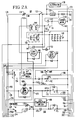
- Figure 1 is a partially block and partially schematic diagram of a transport refrigeration system having a refrigerant compressor driven by an internal combustion engine, which may utilize the methods of the invention;
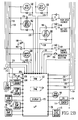
- Figures 2A and 2B may be assembled to provide an electrical schematic diagram of microprocessor based electrical control shown in block form in Figure 1;
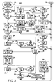
- Figure 3 is a flow diagram of a program which sets forth a microprocessor controlled temperature check of the internal combustion engine which drives the refrigerant compressor utilized in the transport refrigeration system; and
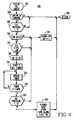
- Figure 4 is a flow diagram of a program which sets forth a microprocessor controlled oil pressure check of the internal combustion engine.
- Referring now to the drawing, and to Figure 1 in particular, there is shown a
transport refrigeration unit 20 which may utilize the methods of the invention.Refrigeration unit 20 may be mounted on a container, truck, or trailer, such as on awall 22 thereof, for example.Refrigeration unit 20 has a closedfluid refrigerant circuit 24 which includes arefrigerant compressor 26 driven by aprime mover arrangement 28.Prime mover arrangement 28 includes aninternal combustion engine 30, and it may optionally include a stand-byelectric motor 32.Engine 30 andmotor 32 are coupled tocompressor 26 by a suitable clutch orcoupling 34 which disengagesengine 30 whilemotor 32 is operative. Aselector 35 selects one of the two prime movers and provides an output signal to identify the selection. - Discharge ports of
compressor 26 are connected to an inlet port of a three-way valve 36 via adischarge service valve 38 and ahot gas line 40. The functions of three-way valve 36, which selects heating and cooling cycles, may be provided by two separate valves, if desired. Three-way valve 36 has afirst output port 42, which is selected to initiate a cooling cycle, with thefirst output port 42 being connected to the inlet side of a condenser coil 44. Three-way valve 36 has asecond outlet port 46, which is selected to initiate a heating cycle, as will be hereinafter described. - When three-
way valve 36 selects the coolingcycle output port 42, it connectscompressor 26 in afirst refrigerant circuit 48, which in addition to condenser 44, includes a one-way condenser check valve CV1, areceiver 50, aliquid line 52, arefrigerant drier 54, aheat exchanger 56, anexpansion valve 58, arefrigerant distributor 60, anevaporator coil 62, an optional controllable suctionline modulation valve 64, another path throughheat exchanger 56, anaccumulator 66, asuction line 68, and back to a suction port ofcompressor 26 via a suctionline service valve 70. The operative prime mover may be protected against overload by controllingmodulation valve 64 to provide the function of a conventional compressor throttling valve, as taught by U.S. Patent 4,977,751, which is assigned to the same assignee as the present application; or, a conventional compressor throttling valve may be disposed insuction line 68, as desired.Expansion valve 58 is controlled by athermal bulb 71 and anequalizer line 73. - When three-
way valve 36 selects the heatingcycle output port 46, it connectscompressor 26 in asecond refrigerant circuit 72. Thesecond refrigerant circuit 72 by-passes condenser 44 andexpansion valve 58, connecting the hot gas output ofcompressor 26 to therefrigerant distributor 60 via ahot gas line 74 and adefrost pan heater 76. A hot gas by-pass solenoid valve 77 may optionally be disposed inhot gas line 74. A by-pass or pressurizingline 78 connectshot gas line 74 toreceiver 50 via by-pass andcheck valves 80, to force refrigerant fromreceiver 50 into an active refrigerant circuit during heating and defrost cycles. - A conduit or
line 82 connects three-way valve 36 to the low side ofcompressor 26 via a normally closed pilot solenoid valve PS. When solenoid valve PS is de-energized and thus closed, three-way valve 18 is spring biased to select the coolingcycle output port 42. Whenevaporator 62 requires defrosting, and when the load being conditioned requires heat to maintain set point, pilot solenoid valve PS is energized to allow the low pressure side ofcompressor 26 to operate three-way valve 36 to select the heatingcycle output port 46. - A condenser fan or blower (not shown) causes
ambient air 84 to flow through condenser coil 44, with the resultingheated air 86 being discharged to the atmosphere. An evaporator fan or blower (not shown) draws air 88, called "return air", from a servedspace 90 whose air is to be conditioned, through theevaporator coil 62, and the resulting cooled or heatedair 92, called "discharge air", is returned to thespace 90. During an evaporator defrost cycle, the evaporator fan or blower is not operated, and a defrost air damper may be operated to close the discharge air path to the conditionedspace 90. -
Transport refrigeration unit 20 is controlled by microprocessor basedelectrical control 94 which includes amicroprocessor 96 andelectrical control 98.Electrical control 98 includes relays, and the like, as will be explained relative to Figures 2A and 2B. Themicroprocessor 96 receives input signals from appropriate sensors, such as from a returnair temperature sensor 100 disposed in a suitablereturn air path 102, a dischargeair temperature sensor 104 disposed in a suitabledischarge air path 106, from acoil temperature sensor 108 disposed to sense the temperature of theevaporator coil 62, from a refrigerant pressure sensor (HPCO) 110 disposed on the high side of therefrigerant circuit 48, and from various engine sensors shown in Figure 2B, such asoil level sensor 112 ,oil pressure sensor 114, enginecoolant level sensor 115, enginecoolant temperature sensor 116, andengine speed sensor 118. -
Microprocessor 96, among other things, controlsmodulation valve 64, hot gas solenoid valve 77, and a throttle orhigh speed solenoid 120. Other functions controlled bymicroprocessor 96 are shown in Figures 2A and 2B, and will be hereinafter described. - Figures 2A and 2B may be assembled to provide a detailed schematic diagram of microprocessor based
electrical control 94, which includesmicroprocessor 96 andcontrol 98. As is well known,microprocessor 96 includes a read-only memory (ROM) 122 for storing programs to be hereinafter described, and a random access memory (RAM) 124 for software timers, flags, input signals, output signals, and other values generated by the operating programs.Microprocessor 96 also includes adisplay 125 for displaying fault codes, system status indicating lights, and the like. -
Electrical control 98 includes abattery 126 which has one side connected to afirst conductor 128 via aDC shunt 130, an on-off switch 132, and normally closedcontacts 134 of a protective reset switch SSW. The remaining side ofbattery 126 is connected toconductor 136, which is grounded.Control 98 further includes analternator 138 driven byprime mover 28; astarter motor 140, for crankingengine 30, which is controlled by astarter solenoid 142 having associated normallyopen contacts 143, an ignition switch 144, and astart relay 146 having associated normallyopen contacts 147; and glow plug resistors (GP) 148, forpre-heating engine 30, which are controlled by apre-heat switch 150 and by apre-heat relay 152 which has normally opencontacts 153. -
Control 98 also includes a three-position switch 154 which has two banks of three terminals each comprising a center terminal and upper and lower terminals, with reference to Figure 2A.Switch 154, in the illustrated upper position which connects the center terminal to the upper terminal, placesunit 20 under control of themicroprocessor 96. The upper position provides voltage fromconductor 128 to aconductor 155. An intermediate position ofswitch 154, in which the center terminal is not connected to either the upper terminal or the lower terminal, is selected when themicroprocessor 96 is not utilized and the load in the conditionedspace 90 is frozen. This switch position will causeunit 20 to operate continuously in a low speed cool mode. The lower position ofswitch 154 is selected when themicroprocessor 96 is not utilized and the load in the conditioned space is fresh. This position ofswitch 154 will cause unit 10 to operate continuously, cycling between heating and cooling cycles under the control of the hereinbefore mentionedcoil temperature switch 108.Coil temperature switch 108 is preset to close at a predetermined coil temperature, such as 35°F (1.7°C), to energize the pilot solenoid PS and initiate a heating cycle, and to open at a predetermined higher temperature, such as 38°F (3.3°C), to de-energize pilot solenoid PS and initiate a cooling cycle. - In addition to the relays already mentioned,
control 98 includes ashutdown relay 156, arun relay 158, aheat relay 160, ahigh speed relay 162, adefrost damper relay 164, and ahot gas relay 166.Shutdown relay 156 is normally energized, and is de-energized to shut unit 10 down via its associated set of normally-closedcontacts 168 which ground the protective switch SSW and cause it to open itscontacts 134. Therun relay 158 has normally-closed and normallyopen contacts 170 and 172, respectively, connected to amode selector switch 174 which has an input connected toconductor 128.Selector switch 174 selects either a continuous operating mode in which theprime mover 28 operates continuously, or a cycling start-stop mode, also called "cycle sentry", which includes starting and stopping theprime mover 28. - The normally-closed contacts 170 of
run relay 158 are connected to the "continuous" position ofselector switch 174, and the normally-open contacts 172 ofrun relay 158 are connected to the "cycling" position ofselector switch 174. Contacts 170 orcontacts 172 provide voltage to aconductor 175 fromconductor 128 andselector switch 174. -
Heat relay 160 has a set of normallyopen contacts 176 for controlling the pilot solenoid PS.High speed relay 162 has a set of normallyopen contacts 178 for controlling thehigh speed solenoid 120. Damper relay has a set of normally closedcontacts 180 and a set of normallyopen contacts 182, connected to control adefrost damper solenoid 184.Hot gas relay 166 is provided for controlling the hot gas solenoid valve 77 via a set of normallyopen contacts 186, when a hot gas solenoid 77 is provided inhot gas line 74. -
Control 98 also includes a engine coolant temperature switch (high water temperature -HWT) 190, which closes when the engine coolant reaches a predetermined elevated temperature, and a low oil pressure switch (LOPS) 192 which is open as long as engine pressure is normal. The closing of eitherswitch unit 20 down via the manual reset switch SSW. -
Microprocessor 96 senses the voltage acrossDC shunt 130 viaconductors battery 126 is being charged byalternator 138, which also indicates theprime mover 28 is running. The other polarity, ie., negative, indicates the battery is discharging. -
Microprocessor 96 also has aconductor 198 which senses the position of the lowoil pressure switch 192,conductors out switch 110, aconductor 204 which senses whether or not a modulationvalve selector jumper 206 has connectedconductor 204 tosystem ground 136, aconductor 208 which senses whether or not adefrost sensor switch 210 has operated, signifying the need for a defrost cycle, and aconductor 211 which detects voltage on thedamper solenoid 184. -
Microprocessor 96 has a plurality of output conductors for controlling various functions, includingconductors start relay 146,pre-heat relay 152,shutdown relay 156,damper relay 164,high speed relay 162,run relay 158,heat relay 160, andhot gas relay 166. Aconductor 228 is also provided for controlling the current level in themodulation valve 64. - Referring now to Figure 3, there is shown an engine
temperature monitoring program 230 which sets forth certain teachings of the invention.Program 230 is entered at 232 and step 234 determines ifengine 30 has been selected as the prime mover, and if so, step 234 also determines ifengine 30 running. Ifelectric motor 32 has been selected as the prime mover, orengine 30 has been selected but it is not running, step 234exits program 230 at 236. - If
step 234 findsengine 30 is the prime mover, andengine 30 is running,step 238 determines if the temperature ofengine 30 exceeds a predetermined maximum value. In the exemplary embodiment of the invention,engine 30 is liquid cooled and the temperature ofengine 30 is monitored bywater temperature sensor 116 shown in Figure 2B. Other engine parameters which could be monitored to determine engine temperature include the temperature of the engine block and the temperature of the engine exhaust gases. - The predetermined maximum temperature value used in
step 238 is selected such that if the water temperature exceeds this value, eg., 220°F, it may not be necessary to run portions ofprogram 230 related to detecting conditions which may lead to shutdown, as with an engine temperature above the selected maximum value, shutdown may be imminent. - If
step 238 finds the water temperature above 220°F, step 240 sets a shutdown flag SDF true, which will result in the shutdown ofengine 30, and thusunit 20, ifprogram 230 is exited with flag SDF true. Step 240 also sets an alarm HWT, indicating with an appropriate code indisplay 125 the exact cause of shutdown, ie., high engine water temperature. - Before exiting
program 230 with SDF true, however,program 230 determines if the high engine water temperature is a transitory condition which will shortly drop to a safer level. To determine this, time is provided for the engine temperature to drop below a predetermined value, e.g., below 218°F. To implement this feature, step 240 also starts a timer, such as a software timer inRAM 124. Step 242 updates the timer and the program does not advance until either the engine temperature drops below 218°F, or a predetermined period of time has elapsed, e.g., 25 seconds. - More specifically,
step 244 determines if the engine water temperature has dropped below 218°F, and step 246 detects when the timer started instep 240 reaches 25 seconds.Steps timer updating step 242 until either step 244 or step 246 find "yes" answers to the questions posed by the steps, and step 248 then determines whether the program arrived at this point viastep 244 orstep 246. - If the timer reached 25 seconds, the temperature did not drop below 218° during the 25 second time period, and the true shutdown flag SDF remains true as the program exits at 236 after step 250 turns on a shutdown indicating light on
display 125. - If
step 248 finds the timer did not reach or exceed 25 seconds, then step 244 found that the water temperature dropped below 218°F. Step 248 is then entered which clears the alarm HWT which was set inStep 240. Step 254 determines if there are any other active alarms which will, or have, shutunit 20 down. If there are no other shutdown alarms, step 256 sets the shutdown flag SDF false, and step 256 also energizesshutdown relay 156, in theevent unit 20 had already been shut down. Ifstep 254 finds some other shutdown alarms exist, they are allowed to remain, with bothstep 256 and the "yes" branch fromstep 254 going to step 258. - Step 258 determines if the engine water temperature is below a predetermined value, eg., 190°F (88°C), with this value being a dividing line which separates normal engine temperature from a water temperature range which borders a temperature value which indicates a potential water temperature problem. If
step 258 finds the water temperature is below 190°F (88°C),step 260 determines if there are any water temperature related alarms which have not been cleared. If there are, with the engine water temperature now below 190°F (88°C) these set alarms may be cleared. Accordingly,step 262 clears alarm UFTLS "unit forced to low speed", and it also clears alarm UFTFM "unit forced to full modulation". Step 262 then turns off the alarm light indisplay 125, and the program exits at 236. - If
step 258 finds that the water temperature exceeds 190° (88°C),step 264 determines if the water temperature is high enough, eg., 210°F (99°C), that modification of the operating mode ofunit 20 should be considered, to prevent an eventual shutdown ofunit 20 because of excessive engine temperature. Ifstep 264 finds that the water temperature is between 190°F (88°C) and 210°F (99°C), the water temperature is still in a zone which does not require modification of the operating mode ofunit 20, and the program exits at 236. - If the engine temperature continues to rise and a subsequent running of
program 230 finds that the water temperature is equal to, or higher than 210° (99°C), thenprogram 230 enters a phase to determine if the elevated engine water temperature is transitory. Step 266 starts a software timer inRAM 124,step 268 updates the timer,step 270 checks to see if the water temperature has dropped to, or below, a predetermined value below 210° (99°C), such as 205°F (96°C), and step 272 limits the amount of time which has been provided to determine if the engine water temperature is going to drop. Except for the values of the water temperature and time, steps 266, 268, 270 and 272 are similar to the hereinbefore describedsteps - If the water temperature drops below 205°F (96°C), detected by
step 270, or the timer reaches or exceeds 30 seconds, detected bystep 272, the program arrives atstep 274 which determines whetherstep 270 or step 272 caused the program to reachstep 274. If the timer did not reach the predetermined value, eg., 30 seconds, then the water temperature dropped below 205°F (96°C) and the program exits at 236. If the timer reached or exceeded 30 seconds, then the water temperature did not drop below 205°F (96°C) and step 274 goes to step 276 which sets an alarm "check engine water temperature" (CEWT). - In a preferred embodiment of the invention, before proceeding with the program portion devoted to finding modified operating modes which may keep
unit 20 running, the engine water level is checked instep 278 viawater level sensor 115, to determine if the level is below a predetermined safe level.Sensor 115 may simply be of the type which provides a signal when the water level is below a predetermined level. If the water level is low, as determined bystep 278, then alternative operating modes will not be of benefit, and the program exits at 236. The hereinbefore describedstep 238 will eventually start the shutdown ofengine 30 andunit 20, if the low water level problem is not corrected. Alarm CEWT, generated instep 276, will alert the operator to check the engine water level. - If
step 278 does not find that the engine water level is low, then step 278 advances to step 280 which checkshigh speed relay 162 to determine ifengine 30 is currently running at high speed, eg., 2200 RPM, or low speed, eg., 1400 RPM. Ifengine 30 is running at high speed,program 230 starts a first modification phase withstep 282. Step 282 de-energizeshigh speed relay 162, and its normallyopen contacts 178 open to de-energizehigh speed solenoid 120 and dropengine 30 to the low speed setting. Step 284 then continues the first modification phase by setting the hereinbefore mentioned alarm UFTLS, which notifies the operator that the operation ofunit 20 has been modified by forcing it to low speed. Step 284 also turns on the alarm indicator light indisplay 125, so the operator's attention will be directed to the alarm code portion ofdisplay 125. -
Program 230 then provides time for the first phase modification to work, by setting a timer instep 284. The timer is updated instep 286. Step 288 detects the dropping of the engine water temperature into the safe range, ie., below 190°F (88°C). Step 290 terminates the test period if the engine water temperature does not fall into the safe range after a predetermined period of time, eg., 5 minutes. Step 292 determines whetherstep 288 or step 290 caused the program to break out of the loop which includessteps step 292 finds that the water temperature dropped into the safe range, then the program exits at 236. The hereinbefore describedstep 262 will clear alarm UFTLS during the next running ofprogram 230. - If
step 292 finds that the timer reached 5 minutes, then the engine water temperature did not drop into the safe range, andprogram 230 starts a second modification phase to further modify the operation ofunit 20 in an attempt to provide an operational mode which will prevent an eventual shutdown ofunit 20 due to high engine water temperature. This second phase starts withstep 294 which determines if the present operational mode is "low speed, full modulation". Full modulation indicates that suctionline modulation valve 64 is fully closed, with full modulation reducing the load onengine 30. If the program arrived atstep 294 fromstep 282, the operational mode should be "low speed", and the microprocessor checks to see if it is providing a signal which causes themodulation valve 64 to fully close. If suctionline modulation valve 64 is fully closed, thenunit 20 is already in low speed, full modulation, and the program exits at 236. If the engine water temperature continues to rise whileunit 20 is in low speed, full modulation, then the hereinbefore describedstep 238 will eventually start shutdown ofunit 20. - If
step 294 finds thatunit 20 is not in a low speed, full modulation operating mode, the second phase of the operating condition modification quest continues, withstep 296 causing microprocessor to provide a current sinking path for current throughmodulation valve 64 which increases the modulation valve current to the magnitude required to fullyclose valve 64. Step 296 also disables thehigh speed relay 162, to prevent some other program from switchingengine 30 to high speed. Step 296 also sets the hereinbefore mentioned alarms UFTLS and UFTFM, it turns the alarm indicator light indisplay 125 on, and the program exits at 236. As hereinbefore stated, if the operational mode modifications initiated byprogram 230 do not keep the water temperature from eventually reaching 220°F (105°C), the hereinbefore describedstep 238 will initiate the shutdown process. - If
step 280 finds thatengine 30 is already in low speed then the first modification phase is skipped, and the second modification phase is immediately entered, withstep 280 going to the hereinbefore describedstep 294. - The methods of the invention also include monitoring engine oil pressure, with Figure 4 setting forth a
program 300 for monitoring engine oil pressure.Program 300 is entered at 302 and step 304 determines ifengine 30 is the selected prime mover, and that it is running. If not, the program exits at 306. - If
engine 30 is selected as the compressor prime mover, andengine 30 is running, step 308 checks to see if the engine oil pressure is below a predetermined value, eg., 15 psi (1.035 bar), which gives rise to concern.Oil pressure sensor 114 may be of the type which provides an input to microprocessor which indicates whether or not the engine oil pressure is below the predetermined value. If the engine oil pressure is not below 15 psi, the oil pressure is O.K. andprogram 300 exits at 306. - If
step 308 finds that the engine oil pressure is below 15 psi (1.035 bar), then step 310 determines if modification of the current operating mode ofunit 20 may be beneficial. Step 310 checks thehigh speed relay 162 to determine ifengine 30 is running at the low or high speed settings of the engine throttle. Ifengine 30 is running at high speed, then modification of the operating mode ofunit 20 would not be beneficial, and step 312 sets alarm LOP, indicating low engine oil pressure. Shutdown flag SDF is also set true instep 312, as continued operation with low oil pressure may damageengine 30. Step 312 also turns on an alarm indicator light indisplay 125. - If
step 310 finds thatengine 30 is operating in low speed, then, if the oil level is not low, the engine oil pressure may possibly be raised by going to the high engine speed setting. Step 314 first checks theoil level sensor 112 instep 314 to detect a low oil level.Oil level sensor 112 may be of the type which provides a predetermined output when the engine oil level drops below a predetermined level. Ifoil level sensor 112 indicates that the oil level is low, then step 314 goes to step 312 to start the shutdown process. - If the oil level is not low,
step 314 continues the modification phase ofprogram 300 by going to step 316 which energizeshigh speed relay 162. Normallyopen contacts 178 ofhigh speed relay 162 close, andhigh speed solenoid 120 is energized to move the engine throttle to the high speed setting.Program 300 then provides time for the engine oil pressure to increase after the switch from low to high engine speed, by starting a timer instep 318, updating the timer instep 320, and determining when a predetermined time period has elapsed, eg., 5 seconds. After 5 seconds,step 324 checksoil pressure sensor 114 to determine if high speed engine operation has raised the engine oil pressure to, or above, the oil pressure setting, which is 15 psi (1.035 bar) in the example. If the modification of the operating mode from low speed to high speed did not raise the oil pressure out of the danger zone, then step 324 goes to the hereinbefore describedstep 312 to start the shutdown process. - If
step 324 finds the engine oil pressure has been raised to, or above, 15 psi (1.035 bar), thenprogram 300 allowsengine 30 to operate at high speed, exiting at 306 after setting alarms CEOP and UFTHS, and turning the on the alarm light indisplay 125. Alarm CEOP alerts the operator to check the engine oil pressure, and alarm UFTHS notifies the operator that the unit has been forced to high speed operation.


Claims (11)
- A method of operating a refrigeration unit (20) when a condition is detected which may result in shutdown of the unit, with the refrigeration unit having a refrigerant compressor (26) driven at low and high speeds by an internal combustion engine (30), with the engine including a temperature sensor (116), comprising the steps of:
monitoring (116) the temperature of the engine,
detecting (264) if a predetermined over-temperature condition exists by comparing the monitored (116) temperature of the engine with a predetermined value;
initiating a first modification of the refrigeration unit, including the step of switching (282) the engine to low speed when it is in high speed (280) at the time the detecting step detects the predetermined overtemperature condition,
determining (292) if the engine temperature has dropped below a predetermined value after the step of switching to low speed,
initiating (296) a second modification of the refrigeration unit when the engine temperature does not drop below the predetermined value, comprising
maintaining (294) the engine at low speed when it is in low speed when the detecting step (264) detects the predetermined over-temperature condition, and
initiating (296) the second modification of the refrigeration unit immediately when the engine is in low speed at the time the detecting step (264) detects the predetermined over-temperature condition, the refrigeration unit including a controllable suction line modulation valve (64), with the second modification of the refrigeration unit including the step of switching (296) the refrigeration unit to full modulation. - The method of claim 1 including the step of generating (296) an alarm in response to initiating the second modification.
- The method of claim 1 including the step of providing time (284, 286, 290, 292) for the engine to run at low speed in response to the step of switching from high to low speed, before initiating the step of determining if the engine temperature dropped below the predetermined value.
- The method of claim 1 wherein the engine is liquid cooled, with the temperature sensor sensing the temperature of the liquid coolant, and wherein the step of monitoring the temperature of the engine monitors the temperature of the liquid coolant.
- The method of claim 1 wherein the engine is liquid cooled and has a liquid coolant level sensor (115), and including the steps of monitoring (115) the level of the engine coolant, and detecting (278) when the coolant level is below a predetermined level, with the steps of initiating the first and second modifications taking place only if the level of the engine coolant is at or above the predetermined level.
- The method of claim 1 including the steps of providing time (266, 268, 270, 272) after the predetermined over-temperature condition is detected for the temperature of the engine to drop below a predetermined value, and determining (274) if the temperature of the engine has dropped below the predetermined value, with the steps of initiating the second modifications taking place only when the determining step finds the temperature of the engine has not dropped below the predetermined value.
- The method of claim 1 including the step of shutting (240, 250) the engine and refrigeration unit down when the temperature of the engine exceeds a predetermined maximum value.
- The method of claim 7 including the steps of providing time (240, 242, 244, 246) for the temperature of the engine to drop a predetermined amount below the maximum value, and determining (248) if the engine temperature has dropped the predetermined amount below the maximum value, with the step of shutting the engine and refrigeration unit down taking place only when engine temperature fails to drop the predetermined amount.
- The method of claim 1 wherein the engine includes an oil pressure sensor (114), and including the steps of:
monitoring (114) the oil pressure of the engine, detecting (308) a predetermined low oil pressure condition,
switching (316) the engine to high speed when it is in low speed (310) at the time the detecting step detects the predetermined low oil pressure condition,
determining (324) if the engine oil pressure has increased above a predetermined value after the step of switching to high speed,
continuing (326) to operate the engine at high speed when the determining step finds the engine oil pressure has increased above the predetermined value, and shutting (312) the engine down when the determining step finds the engine oil pressure did not increase above the predetermined value. - The method of claim 9 including the step of providing time (318, 320, 322), after the step of switching the engine to high speed, before initiating the step of determining if the engine oil pressure increased above the predetermined value.
- The method of claim 9 wherein the engine has an oil level sensor (112), and including the steps of monitoring (112) the level of the engine oil, and detecting (314) a predetermined low oil pressure condition, with the step of switching the engine to high speed taking place only when the detecting step has not detected the predetermined low oil pressure condition.
Priority Applications (1)
| Application Number | Priority Date | Filing Date | Title |
|---|---|---|---|
| EP94109064A EP0623791B1 (en) | 1991-07-11 | 1992-07-08 | A method of operating a transport refrigeration unit |
Applications Claiming Priority (2)
| Application Number | Priority Date | Filing Date | Title |
|---|---|---|---|
| US728465 | 1991-07-11 | ||
| US07/728,465 US5201186A (en) | 1991-07-11 | 1991-07-11 | Method of operating a transport refrigeration unit |
Related Child Applications (1)
| Application Number | Title | Priority Date | Filing Date |
|---|---|---|---|
| EP94109064.9 Division-Into | 1994-06-14 |
Publications (3)
| Publication Number | Publication Date |
|---|---|
| EP0522847A2 EP0522847A2 (en) | 1993-01-13 |
| EP0522847A3 EP0522847A3 (en) | 1993-03-31 |
| EP0522847B1 true EP0522847B1 (en) | 1995-05-24 |
Family
ID=24926967
Family Applications (2)
| Application Number | Title | Priority Date | Filing Date |
|---|---|---|---|
| EP94109064A Expired - Lifetime EP0623791B1 (en) | 1991-07-11 | 1992-07-08 | A method of operating a transport refrigeration unit |
| EP92306281A Expired - Lifetime EP0522847B1 (en) | 1991-07-11 | 1992-07-08 | A method of operating a transport refrigeration unit |
Family Applications Before (1)
| Application Number | Title | Priority Date | Filing Date |
|---|---|---|---|
| EP94109064A Expired - Lifetime EP0623791B1 (en) | 1991-07-11 | 1992-07-08 | A method of operating a transport refrigeration unit |
Country Status (6)
| Country | Link |
|---|---|
| US (1) | US5201186A (en) |
| EP (2) | EP0623791B1 (en) |
| JP (1) | JP3192231B2 (en) |
| CA (2) | CA2073612C (en) |
| DE (2) | DE69222541T2 (en) |
| ES (2) | ES2073247T3 (en) |
Families Citing this family (32)
| Publication number | Priority date | Publication date | Assignee | Title |
|---|---|---|---|---|
| JP2794142B2 (en) * | 1992-09-14 | 1998-09-03 | 株式会社山武 | Information processing device |
| US5249429A (en) * | 1993-02-08 | 1993-10-05 | Thermo King Corporation | Methods of operating a refrigeration system |
| US5284024A (en) * | 1993-02-25 | 1994-02-08 | Thermo King Corporation | Method of detecting short cycling of air discharged by a refrigeration unit |
| US5454229A (en) * | 1994-05-18 | 1995-10-03 | Thermo King Corporation | Refrigeration unit control with shutdown evaluation and automatic restart |
| US5557938A (en) * | 1995-02-27 | 1996-09-24 | Thermo King Corporation | Transport refrigeration unit and method of operating same |
| US5579648A (en) * | 1995-04-19 | 1996-12-03 | Thermo King Corporation | Method of monitoring a transport refrigeration unit and an associated conditioned load |
| US5572879A (en) * | 1995-05-25 | 1996-11-12 | Thermo King Corporation | Methods of operating a refrigeration unit in predetermined high and low ambient temperatures |
| US6249726B1 (en) | 1998-12-16 | 2001-06-19 | Kold Ban International, Ltd. | Method and apparatus for responding to failure of a load |
| US6237420B1 (en) * | 1998-12-21 | 2001-05-29 | Texas Instruments Incorporated | Differential oil pressure control apparatus and method |
| US6226998B1 (en) * | 1999-03-26 | 2001-05-08 | Carrier Corporation | Voltage control using engine speed |
| US6196012B1 (en) | 1999-03-26 | 2001-03-06 | Carrier Corporation | Generator power management |
| US6148627A (en) * | 1999-03-26 | 2000-11-21 | Carrier Corp | High engine coolant temperature control |
| US6931884B2 (en) * | 2001-03-27 | 2005-08-23 | Thermo King Corporation | Undermount transport temperature control unit |
| US6679074B2 (en) | 2001-07-31 | 2004-01-20 | Thermo King Corporation | Automatic switching refrigeration system |
| US6871629B2 (en) * | 2001-07-31 | 2005-03-29 | Thermo King Corporation | Refrigeration system with low-fuel shutdown |
| US6996997B2 (en) * | 2003-03-05 | 2006-02-14 | Thermo King Corporation | Pre-trip diagnostic methods for a temperature control unit |
| US6708507B1 (en) | 2003-06-17 | 2004-03-23 | Thermo King Corporation | Temperature control apparatus and method of determining malfunction |
| US6910341B2 (en) * | 2003-09-26 | 2005-06-28 | Thermo King Corporation | Temperature control apparatus and method of operating the same |
| MY140672A (en) * | 2005-06-23 | 2010-01-15 | Honda Motor Co Ltd | Engine oil level detection system |
| US20090299534A1 (en) * | 2008-05-30 | 2009-12-03 | Thermo King Corporation | Start/stop temperature control operation |
| PT2180277E (en) | 2008-10-24 | 2015-11-23 | Johnson Controls Tech Co | Controlling chilled state of a cargo |
| US8538585B2 (en) * | 2008-10-24 | 2013-09-17 | Thermo King Corporation | Control of pull-down in refrigeration systems |
| US20100106302A1 (en) * | 2008-10-24 | 2010-04-29 | Ole Thogersen | Controlling frozen state of a cargo |
| JP5266039B2 (en) * | 2008-12-25 | 2013-08-21 | 日野自動車株式会社 | Intercooler abnormality detection device |
| US10107536B2 (en) | 2009-12-18 | 2018-10-23 | Carrier Corporation | Transport refrigeration system and methods for same to address dynamic conditions |
| US8590330B2 (en) * | 2010-06-03 | 2013-11-26 | Thermo King Corporation | Electric transport refrigeration unit with temperature-based diesel operation |
| CN103167964B (en) | 2010-09-28 | 2016-03-23 | 开利公司 | Run transport refrigeration system in case engine off and overload |
| WO2017192568A1 (en) | 2016-05-03 | 2017-11-09 | Carrier Corporation | Intelligent voltage control for electric heat and defrost in transport refrigeration system |
| ES2902405T3 (en) * | 2017-01-27 | 2022-03-28 | Carrier Corp | Apparatus and method for the detection of thermal events in a transport refrigeration unit |
| US11378290B2 (en) * | 2017-10-06 | 2022-07-05 | Daikin Applied Americas Inc. | Water source heat pump dual functioning condensing coil |
| US11686520B2 (en) * | 2017-10-31 | 2023-06-27 | Carrier Corporation | System for transport refrigeration control of multiple compartments |
| JP7410621B2 (en) | 2019-12-18 | 2024-01-10 | キヤノン株式会社 | Imaging device, its control method, and program |
Family Cites Families (17)
| Publication number | Priority date | Publication date | Assignee | Title |
|---|---|---|---|---|
| US3904885A (en) * | 1973-12-03 | 1975-09-09 | Hollins J R | Motor vehicle air conditioner control system |
| US4071839A (en) * | 1976-05-27 | 1978-01-31 | Hollins J R | Motor vehicle air conditioner control and warning system |
| US4324286A (en) * | 1980-03-24 | 1982-04-13 | The Trane Company | Control for vehicle temperature conditioning system |
| US4535598A (en) * | 1984-05-14 | 1985-08-20 | Carrier Corporation | Method and control system for verifying sensor operation in a refrigeration system |
| US4663725A (en) * | 1985-02-15 | 1987-05-05 | Thermo King Corporation | Microprocessor based control system and method providing better performance and better operation of a shipping container refrigeration system |
| US4642770A (en) * | 1985-04-18 | 1987-02-10 | Deere & Company | Vehicle accessory control system |
| US4765150A (en) * | 1987-02-09 | 1988-08-23 | Margaux Controls, Inc. | Continuously variable capacity refrigeration system |
| JPS63177684U (en) * | 1987-05-07 | 1988-11-17 | ||
| JPS6422617A (en) * | 1987-07-17 | 1989-01-25 | Nissan Motor | Air conditioner for vehicle |
| JP2661121B2 (en) * | 1988-03-31 | 1997-10-08 | 日産自動車株式会社 | Vehicle air conditioners and variable displacement compressors |
| US4878465A (en) * | 1988-08-26 | 1989-11-07 | Thermo King Corporation | Control for automatically starting a diesel engine |
| DE3829635A1 (en) * | 1988-09-01 | 1990-03-15 | Bosch Gmbh Robert | METHOD AND CIRCUIT FOR CONTROLLING A CONSUMER DRIVED BY AN INTERNAL COMBUSTION ENGINE |
| US4918932A (en) * | 1989-05-24 | 1990-04-24 | Thermo King Corporation | Method of controlling the capacity of a transport refrigeration system |
| US4995357A (en) * | 1989-11-13 | 1991-02-26 | Briggs & Stratton Corporation | Engine shut-off circuit |
| US4977751A (en) * | 1989-12-28 | 1990-12-18 | Thermo King Corporation | Refrigeration system having a modulation valve which also performs function of compressor throttling valve |
| US5054294A (en) * | 1990-09-21 | 1991-10-08 | Carrier Corporation | Compressor discharge temperature control for a variable speed compressor |
| US5070832A (en) * | 1991-03-29 | 1991-12-10 | Cummins Engine Company, Inc. | Engine protection system |
-
1991
- 1991-07-11 US US07/728,465 patent/US5201186A/en not_active Expired - Fee Related
-
1992
- 1992-07-08 ES ES92306281T patent/ES2073247T3/en not_active Expired - Lifetime
- 1992-07-08 ES ES94109064T patent/ES2110145T3/en not_active Expired - Lifetime
- 1992-07-08 DE DE69222541T patent/DE69222541T2/en not_active Expired - Fee Related
- 1992-07-08 DE DE69202630T patent/DE69202630T2/en not_active Expired - Lifetime
- 1992-07-08 EP EP94109064A patent/EP0623791B1/en not_active Expired - Lifetime
- 1992-07-08 EP EP92306281A patent/EP0522847B1/en not_active Expired - Lifetime
- 1992-07-10 JP JP20734192A patent/JP3192231B2/en not_active Expired - Fee Related
- 1992-07-10 CA CA002073612A patent/CA2073612C/en not_active Expired - Fee Related
- 1992-07-10 CA CA002284497A patent/CA2284497C/en not_active Expired - Fee Related
Also Published As
| Publication number | Publication date |
|---|---|
| EP0522847A3 (en) | 1993-03-31 |
| EP0522847A2 (en) | 1993-01-13 |
| DE69222541D1 (en) | 1997-11-06 |
| ES2073247T3 (en) | 1995-08-01 |
| DE69202630T2 (en) | 1996-02-01 |
| JP3192231B2 (en) | 2001-07-23 |
| JPH05187738A (en) | 1993-07-27 |
| CA2284497A1 (en) | 1993-01-12 |
| CA2073612A1 (en) | 1993-01-12 |
| DE69202630D1 (en) | 1995-06-29 |
| EP0623791A3 (en) | 1995-06-21 |
| CA2284497C (en) | 2001-01-02 |
| EP0623791B1 (en) | 1997-10-01 |
| DE69222541T2 (en) | 1998-04-02 |
| EP0623791A2 (en) | 1994-11-09 |
| US5201186A (en) | 1993-04-13 |
| CA2073612C (en) | 2000-09-12 |
| ES2110145T3 (en) | 1998-02-01 |
Similar Documents
| Publication | Publication Date | Title |
|---|---|---|
| EP0522847B1 (en) | A method of operating a transport refrigeration unit | |
| US5222368A (en) | Method of operating a transport refigeration unit | |
| US5454229A (en) | Refrigeration unit control with shutdown evaluation and automatic restart | |
| US5123252A (en) | Method of operating a transport refrigeration unit | |
| CA2170311C (en) | Transport refrigeration unit and method of operation same | |
| US5579648A (en) | Method of monitoring a transport refrigeration unit and an associated conditioned load | |
| US5172561A (en) | Pre-trip diagnostic methods for a transport refrigeration unit | |
| US5140826A (en) | Method of operating a transport refrigeration unit | |
| US5123253A (en) | Method of operating a transport refrigeration unit | |
| US5303560A (en) | Method and apparatus for monitoring and controlling the operation of a refrigeration unit | |
| US5201185A (en) | Method of operating a transport refrigeration unit | |
| EP0522849B1 (en) | Detection of engine fuel problems | |
| US5161383A (en) | Method of operating a transport refrigeration unit | |
| US5291745A (en) | Method of improving temperature uniformity of a space conditioned by a refrigeration unit | |
| US5284024A (en) | Method of detecting short cycling of air discharged by a refrigeration unit | |
| US5596878A (en) | Methods and apparatus for operating a refrigeration unit | |
| US5161384A (en) | Method of operating a transport refrigeration system | |
| US5275011A (en) | Method of operating a refrigeration system | |
| US5140825A (en) | Method of operating a transport refrigeration unit | |
| US4735055A (en) | Method of operating a transport refrigeration system having a six cylinder compressor | |
| US5123251A (en) | Method of operating a transport refrigeration unit | |
| US5197670A (en) | Method of operating a transport refrigeration unit | |
| JP4039773B2 (en) | Refrigeration equipment | |
| JPH0137669B2 (en) |
Legal Events
| Date | Code | Title | Description |
|---|---|---|---|
| PUAI | Public reference made under article 153(3) epc to a published international application that has entered the european phase |
Free format text: ORIGINAL CODE: 0009012 |
|
| AK | Designated contracting states |
Kind code of ref document: A2 Designated state(s): DE ES FR GB IT |
|
| PUAL | Search report despatched |
Free format text: ORIGINAL CODE: 0009013 |
|
| AK | Designated contracting states |
Kind code of ref document: A3 Designated state(s): DE ES FR GB IT |
|
| 17P | Request for examination filed |
Effective date: 19930924 |
|
| 17Q | First examination report despatched |
Effective date: 19940420 |
|
| GRAA | (expected) grant |
Free format text: ORIGINAL CODE: 0009210 |
|
| AK | Designated contracting states |
Kind code of ref document: B1 Designated state(s): DE ES FR GB IT |
|
| XX | Miscellaneous (additional remarks) |
Free format text: TEILANMELDUNG 94109064.9 EINGEREICHT AM 08/07/92. |
|
| REF | Corresponds to: |
Ref document number: 69202630 Country of ref document: DE Date of ref document: 19950629 |
|
| ET | Fr: translation filed | ||
| REG | Reference to a national code |
Ref country code: ES Ref legal event code: FG2A Ref document number: 2073247 Country of ref document: ES Kind code of ref document: T3 |
|
| ITF | It: translation for a ep patent filed |
Owner name: PROROGA CONCESSA IN DATA: 10.10.95;ING. ZINI MARAN |
|
| PLBE | No opposition filed within time limit |
Free format text: ORIGINAL CODE: 0009261 |
|
| STAA | Information on the status of an ep patent application or granted ep patent |
Free format text: STATUS: NO OPPOSITION FILED WITHIN TIME LIMIT |
|
| 26N | No opposition filed | ||
| REG | Reference to a national code |
Ref country code: GB Ref legal event code: IF02 |
|
| PGFP | Annual fee paid to national office [announced via postgrant information from national office to epo] |
Ref country code: GB Payment date: 20020703 Year of fee payment: 11 |
|
| PGFP | Annual fee paid to national office [announced via postgrant information from national office to epo] |
Ref country code: ES Payment date: 20020807 Year of fee payment: 11 |
|
| PG25 | Lapsed in a contracting state [announced via postgrant information from national office to epo] |
Ref country code: GB Free format text: LAPSE BECAUSE OF NON-PAYMENT OF DUE FEES Effective date: 20030708 |
|
| PG25 | Lapsed in a contracting state [announced via postgrant information from national office to epo] |
Ref country code: ES Free format text: LAPSE BECAUSE OF NON-PAYMENT OF DUE FEES Effective date: 20030709 |
|
| PGFP | Annual fee paid to national office [announced via postgrant information from national office to epo] |
Ref country code: FR Payment date: 20030718 Year of fee payment: 12 |
|
| GBPC | Gb: european patent ceased through non-payment of renewal fee |
Effective date: 20030708 |
|
| REG | Reference to a national code |
Ref country code: ES Ref legal event code: FD2A Effective date: 20030709 |
|
| PG25 | Lapsed in a contracting state [announced via postgrant information from national office to epo] |
Ref country code: FR Free format text: LAPSE BECAUSE OF NON-PAYMENT OF DUE FEES Effective date: 20050331 |
|
| REG | Reference to a national code |
Ref country code: FR Ref legal event code: ST |
|
| PG25 | Lapsed in a contracting state [announced via postgrant information from national office to epo] |
Ref country code: IT Free format text: LAPSE BECAUSE OF NON-PAYMENT OF DUE FEES Effective date: 20050708 |
|
| PGFP | Annual fee paid to national office [announced via postgrant information from national office to epo] |
Ref country code: DE Payment date: 20110727 Year of fee payment: 20 |
|
| REG | Reference to a national code |
Ref country code: DE Ref legal event code: R071 Ref document number: 69202630 Country of ref document: DE |
|
| REG | Reference to a national code |
Ref country code: DE Ref legal event code: R071 Ref document number: 69202630 Country of ref document: DE |
|
| PG25 | Lapsed in a contracting state [announced via postgrant information from national office to epo] |
Ref country code: DE Free format text: LAPSE BECAUSE OF EXPIRATION OF PROTECTION Effective date: 20120710 |