EP0522690A2 - Antriebsvorrichtung - Google Patents
Antriebsvorrichtung Download PDFInfo
- Publication number
- EP0522690A2 EP0522690A2 EP92304285A EP92304285A EP0522690A2 EP 0522690 A2 EP0522690 A2 EP 0522690A2 EP 92304285 A EP92304285 A EP 92304285A EP 92304285 A EP92304285 A EP 92304285A EP 0522690 A2 EP0522690 A2 EP 0522690A2
- Authority
- EP
- European Patent Office
- Prior art keywords
- motor
- housing
- drive
- roller
- shaft
- Prior art date
- Legal status (The legal status is an assumption and is not a legal conclusion. Google has not performed a legal analysis and makes no representation as to the accuracy of the status listed.)
- Withdrawn
Links
Images

Classifications
-
- E—FIXED CONSTRUCTIONS
- E06—DOORS, WINDOWS, SHUTTERS, OR ROLLER BLINDS IN GENERAL; LADDERS
- E06B—FIXED OR MOVABLE CLOSURES FOR OPENINGS IN BUILDINGS, VEHICLES, FENCES OR LIKE ENCLOSURES IN GENERAL, e.g. DOORS, WINDOWS, BLINDS, GATES
- E06B9/00—Screening or protective devices for wall or similar openings, with or without operating or securing mechanisms; Closures of similar construction
- E06B9/56—Operating, guiding or securing devices or arrangements for roll-type closures; Spring drums; Tape drums; Counterweighting arrangements therefor
- E06B9/62—Counterweighting arrangements
-
- E—FIXED CONSTRUCTIONS
- E06—DOORS, WINDOWS, SHUTTERS, OR ROLLER BLINDS IN GENERAL; LADDERS
- E06B—FIXED OR MOVABLE CLOSURES FOR OPENINGS IN BUILDINGS, VEHICLES, FENCES OR LIKE ENCLOSURES IN GENERAL, e.g. DOORS, WINDOWS, BLINDS, GATES
- E06B9/00—Screening or protective devices for wall or similar openings, with or without operating or securing mechanisms; Closures of similar construction
- E06B9/56—Operating, guiding or securing devices or arrangements for roll-type closures; Spring drums; Tape drums; Counterweighting arrangements therefor
- E06B9/68—Operating devices or mechanisms, e.g. with electric drive
- E06B9/72—Operating devices or mechanisms, e.g. with electric drive comprising an electric motor positioned inside the roller
- E06B2009/725—Operating devices or mechanisms, e.g. with electric drive comprising an electric motor positioned inside the roller with epicyclic or planetary gear train
Definitions
- This invention relates to drive systems, in particular, but not exclusively, to drive systems operable to drive a roller on which an article is wound, such as a rolling shutter, a rolling door, screen, smoke curtain, fire partition curtain or the like.
- Hitherto drive systems have been employed which comprise a motor external to a roller or a motor located within a roller and which include brake means for holding the roller in a selected position whilst power supply is maintained.
- Systems in which the motor is located in a roller have required that a differential gear be located between the motor and roller and the motor and the brake have been located at opposite ends of the roller thereby imposing restrictions on the construction.
- An object of the invention is to provide a system in which the motor is located within the roller and is associated with a brake.
- a drive system comprises a cylindrical housing, a drive motor located within the housing and having at one end an output drive shaft, a holding device located towards the end of the housing opposite to the drive shaft whereby the motor housing can be selectively operated to a braked condition, and a control means for actuating the motor and the holding device in the desired sequence of operation.
- the drive motor includes a brake which brakes the motor when the motor is de-energised.
- the housing is located within a cylindrical roller driven by the motor output shaft and extending in a direction away from the holding device for rotation of the roller independently of the housing.
- the motor may be coupled to the output drive shaft through reduction gearing.
- the roller encloses and is coaxial with the motor housing and is rotatable relative to the housing through bearing means between the housing and the roller.
- the system may comprise a fixed mounting rotatably supporting the housing and power supply means for the motor passing from the mounting to the motor through rotatable connections.
- the housing is drivably connected to shaft means extending in the opposite direction to the motor output shaft and through the mounting, the holding device being associated with said shaft means.
- the holding device includes a keep plate on said shaft means and an electromagnetic brake on said fixed mounting, the keep plate and the brake being operatively associated to actuate the holding means.
- the shaft means may carry a governing device for controlling the rate of rotation of the housing and the shaft means.
- the end of the roller remote from the motor may be associated with counter balancing means whereby, when the holding means is inoperative and the motor de-energised, the roller may be rotated in opposition to the counter balance means.
- the counter balance means may be located within the roller and in the form of spring means.
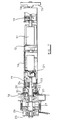
- the drive arrangement illustrated includes a cylindrical housing 10 for a drive motor 11 located internally of the housing, the housing also containing a motor brake 12 which operates to brake the motor when the motor is de-energised.
- Reduction gearing 13 is located between the motor and an output shaft 14 whereby the output from the motor 11 is reduced in speed before being transmitted to the output shaft 14.
- the output shaft 14 is provided with a coupling 15 to transmit drive to, for example, a roller, not shown in Fig. 1.
- the coupling 15 is shown in Fig. 2 secured to a roller 16 acting as driven means.
- the roller 16 encloses the housing, is coaxial thereto and is carried at one end on a bearing 31 on a mounting 18 and on a bearing 17 at the opposite end to the mounting 18.
- the motor 11 and associated housing 10 are rotatable relative to the mounting 18 through a bearing 19.
- the mounting 18 also incorporates slip rings 20 and associated electrical connections 21 and 22 whereby power is rotatably transmitted to the motor 11.
- the end of the housing 10 is adapted to drive a shaft 23 through a planetary gear 24 or may be connected directly to the shaft 23 according to any requirement to increase the speed of the shaft 23 relative to the motor housing 10.
- the shaft 23 extends through the mounting 18 and on the end of the shaft 23 is carried a keep plate 25.
- a holding device 26 Interposed between the keep plate 25 and the mounting 18 is located a holding device 26, usually in the form of an electro magnet, energisation of which causes the magnet 26 to act as a brake preventing rotation of the motor housing 10 relative to the mounting 18.
- the mounting shaft 23 is also adapted to carry a speed governing device 27 comprising expanding shoes which act against the mounting 18 and provide a speed governing function.
- roller 16 extends away from the mounting 18 and the opposite end of the roller 16 to the mounting 18 locates a counter balance arrangement 28, in the form of a counter balance spring.
- a counter balance arrangement 28 in the form of a counter balance spring.
- the spring 28 is connected at one end to the roller 16 and at the other end to the pin 29.
- the roller 16 acts as a support for a weighted curtain 30 which may be the slats of a roller shutter hinged together in known manner, to enable the shutter to be wound on and off the roller 16.
- the sides of the curtain 30 may be located in vertical guides (not shown) or may be unguided.
- Such a curtain can act as a door, a security shutter, a fire or smoke partition, or the like.
- the drive arrangement described can operate in various modes according to the application.
- the motor can be operated to drive the associated roller 16 to raise or lower the associated curtain 30, the motor housing 10 being fixed against rotation by the keep plate 25 and the electro magnet 26.
- the motor brake 12 serves to maintain the curtain in that position.
- the arrangement may be such that the curtain will automatically wind on or off the roller 16 upon release of the holding magnet 26 by the action of the counter balance means and the weight of the curtain according to the balance of forces between the two devices.
- the governing device 27 acts to control the speed of operation.
- the governing means 27 is driven by the roller 16 through the motor housing 10 acting on the planet gear 24 and the drive shaft 23.
- the shaft 23 can be coupled directly to the housing 10.
- the arrangement may be such that the curtain 30 will remain in the same position but may be capable of being freely manually moved with the assistance of the counter balance spring 28.
- the drive provides for manual operation without the requirement of separate manual operation means.
- the motor arrangement described is relatively compact, provides little frictional resistance when operating without power and is thereby capable of manual operation with little effort when the curtain is fully counter balanced. It also provides independently adjustable controlled speed of operation in power loss conditions when used with an out of balance system such as might be needed in an emergency to attract or deploy a shutter or fire protection curtain.
- the drive system described is shown operating directly on the roller but can also be arranged to trans- mitthe power indirectly to an associated roller or other driven arrangement. Similarly the roller can be used to drive other mechanisms than the weighted curtain described.
- the drive arrangement can incorporate limit switches whereby the motor will be stopped in selected raised and/or lowered positions, such limit switches can be arranged to be actuated during operation of the motor 11 or to control the actuation of the holding magnet 26.
- limit switches (not shown) can be incorporated into the drive arrangement in any convenient manner.
- the drive arrangement will include control means whereby the selected mode of operation of the drive motor 11, the holding magnet 26 and the limit switches can be effected.
- the holding device 26 may also be mechanically, pneumatically or hydraulically operated. Similarly the motors 11 and slip rings 20 may be replaced by pneumatic or hydraulic drives and rotating unions.
Landscapes
- Engineering & Computer Science (AREA)
- Structural Engineering (AREA)
- Architecture (AREA)
- Civil Engineering (AREA)
- Operating, Guiding And Securing Of Roll- Type Closing Members (AREA)
Applications Claiming Priority (2)
| Application Number | Priority Date | Filing Date | Title |
|---|---|---|---|
| GB919110575A GB9110575D0 (en) | 1991-05-16 | 1991-05-16 | Drive system |
| GB9110575 | 1991-05-16 |
Publications (2)
| Publication Number | Publication Date |
|---|---|
| EP0522690A2 true EP0522690A2 (de) | 1993-01-13 |
| EP0522690A3 EP0522690A3 (en) | 1993-03-31 |
Family
ID=10695077
Family Applications (1)
| Application Number | Title | Priority Date | Filing Date |
|---|---|---|---|
| EP19920304285 Withdrawn EP0522690A3 (en) | 1991-05-16 | 1992-05-12 | Drive system |
Country Status (2)
| Country | Link |
|---|---|
| EP (1) | EP0522690A3 (de) |
| GB (2) | GB9110575D0 (de) |
Cited By (3)
| Publication number | Priority date | Publication date | Assignee | Title |
|---|---|---|---|---|
| GB2320944B (en) * | 1996-12-23 | 2001-04-25 | Andrew Paul Cooper | Brake arrangement |
| US20150075732A1 (en) * | 2013-09-18 | 2015-03-19 | Lutron Electronics Co., Inc. | Quiet motorized window treatment system |
| EP3218566A4 (de) * | 2014-11-10 | 2018-07-11 | Hunter Douglas Inc. | Abdeckung für eine architektonische öffnung mit mehrstufiger federanordnung |
Families Citing this family (3)
| Publication number | Priority date | Publication date | Assignee | Title |
|---|---|---|---|---|
| GB9400208D0 (en) * | 1994-01-07 | 1994-03-02 | Mansley David L | Flexible doors |
| GB2428737B (en) * | 2005-08-02 | 2010-01-06 | Environmental Seals Ltd | Rolling fire barrier |
| GB2454892B (en) * | 2007-11-22 | 2012-02-01 | Guthrie Douglas Ltd | Fire barrier system |
Citations (3)
| Publication number | Priority date | Publication date | Assignee | Title |
|---|---|---|---|---|
| GB461720A (en) * | 1935-03-07 | 1937-02-23 | Albert Schreiber | Improvements in and relating to automatic actuating-devices for roller-blinds, screens and the like |
| US3285089A (en) * | 1964-04-13 | 1966-11-15 | Nihon Bunka Roller Shutter Com | Drive mechanism for a shutter winding device |
| FR2493906A1 (fr) * | 1980-11-12 | 1982-05-14 | Baldanello U | Volet roulant ou dispositif similaire avec entrainement electrique et commande automatique |
Family Cites Families (1)
| Publication number | Priority date | Publication date | Assignee | Title |
|---|---|---|---|---|
| GB814243A (en) * | 1955-03-24 | 1959-06-03 | Frederick Sidney Cyril Simmons | Improvements in and relating to electric motors particularly for roller blinds |
-
1991
- 1991-05-16 GB GB919110575A patent/GB9110575D0/en active Pending
-
1992
- 1992-05-12 GB GB9210198A patent/GB2257201B/en not_active Expired - Fee Related
- 1992-05-12 EP EP19920304285 patent/EP0522690A3/en not_active Withdrawn
Patent Citations (3)
| Publication number | Priority date | Publication date | Assignee | Title |
|---|---|---|---|---|
| GB461720A (en) * | 1935-03-07 | 1937-02-23 | Albert Schreiber | Improvements in and relating to automatic actuating-devices for roller-blinds, screens and the like |
| US3285089A (en) * | 1964-04-13 | 1966-11-15 | Nihon Bunka Roller Shutter Com | Drive mechanism for a shutter winding device |
| FR2493906A1 (fr) * | 1980-11-12 | 1982-05-14 | Baldanello U | Volet roulant ou dispositif similaire avec entrainement electrique et commande automatique |
Cited By (4)
| Publication number | Priority date | Publication date | Assignee | Title |
|---|---|---|---|---|
| GB2320944B (en) * | 1996-12-23 | 2001-04-25 | Andrew Paul Cooper | Brake arrangement |
| US20150075732A1 (en) * | 2013-09-18 | 2015-03-19 | Lutron Electronics Co., Inc. | Quiet motorized window treatment system |
| US10689905B2 (en) | 2013-09-18 | 2020-06-23 | Lutron Technology Company Llc | Quiet motorized window treatment system |
| EP3218566A4 (de) * | 2014-11-10 | 2018-07-11 | Hunter Douglas Inc. | Abdeckung für eine architektonische öffnung mit mehrstufiger federanordnung |
Also Published As
| Publication number | Publication date |
|---|---|
| GB9210198D0 (en) | 1992-06-24 |
| GB2257201A (en) | 1993-01-06 |
| EP0522690A3 (en) | 1993-03-31 |
| GB2257201B (en) | 1994-12-14 |
| GB9110575D0 (en) | 1991-07-03 |
Similar Documents
| Publication | Publication Date | Title |
|---|---|---|
| US6125586A (en) | Electrically operated slidable door actuator | |
| US5203392A (en) | Mechanism for controlling the raising and lowering of a door | |
| US6530863B2 (en) | Door operator unit | |
| US5711360A (en) | Operating device for rolling shutter assemblies | |
| US6460295B1 (en) | Electrically operated closure actuator | |
| CA2083191C (en) | Spring return rotary actuator | |
| GB2206926A (en) | Improvements in door closers | |
| US20130240165A1 (en) | Motorized Drive Unit Assembly For A Shade System | |
| CA2155466C (en) | An actuating drive having a spring return feature | |
| US4199133A (en) | Battens system for raising and lowering sceneries on a stage | |
| US3646877A (en) | Closure operator | |
| EP0522690A2 (de) | Antriebsvorrichtung | |
| US2746583A (en) | Crane hoist mechanism | |
| US6464043B2 (en) | Elevator emergency escape device | |
| GB2320944A (en) | Roller blind:drum brake | |
| US2571374A (en) | Ventilating fan | |
| CA3157839A1 (en) | Quick release window covering systems and methods of using the same | |
| EP1595056B1 (de) | Aufrollvorrichtung | |
| US6059008A (en) | Braking device for shutter for building | |
| DE19610876C2 (de) | Bremsvorrichtung für einen Rauchgasschutzvorhang, Feuerschutzbehang o. dgl. Behang | |
| US4580463A (en) | Winch for various shutters used for evacuation of smoke and ventilation purposes | |
| RU1811557C (ru) | Устройство дл привода цепной струговой установки | |
| EP0406493A1 (de) | Feuerhemmende Vorhangsanlage | |
| US3886255A (en) | Device including a pulley, a clutch, a retarder, and a brake, in particular for hoisting gears | |
| US4253643A (en) | Escape device |
Legal Events
| Date | Code | Title | Description |
|---|---|---|---|
| PUAI | Public reference made under article 153(3) epc to a published international application that has entered the european phase |
Free format text: ORIGINAL CODE: 0009012 |
|
| AK | Designated contracting states |
Kind code of ref document: A2 Designated state(s): DE FR NL |
|
| PUAL | Search report despatched |
Free format text: ORIGINAL CODE: 0009013 |
|
| AK | Designated contracting states |
Kind code of ref document: A3 Designated state(s): DE FR NL |
|
| STAA | Information on the status of an ep patent application or granted ep patent |
Free format text: STATUS: THE APPLICATION IS DEEMED TO BE WITHDRAWN |
|
| 18D | Application deemed to be withdrawn |
Effective date: 19931002 |